Table of Contents
Advertisement
Quick Links
INSTALLATION AND MAINTENANCE INSTRUCTIONS
B110LPA Plug-in Detector Base
For use with the 1151A and 2151A smoke detectors.
Specifications
Base Diameter:
Base Height:
Weight:
Mounting:
Operating Temperature Range:
Operating Humidity Range:
Electrical Ratings - includes base and detector
System Voltage:
Maximum Ripple Voltage:
Start-up Capacitance:
Standby Ratings:
Alarm Ratings:
Reset Voltage:
Reset Time:
Start-up Time:
Before Installing
Please thoroughly read the System Sensor manual I56-
407, Guide for Proper Use of System Smoke Detectors,
which provides detailed information on detector spacing,
placement, zoning, wiring, and special applications. Cop-
ies of this manual are available at no charge from System
Sensor. Please also refer to CAN/ULC-S524, Standard for
the Installation of Fire Alarm Systems and CEC Part 1,
Sec. 32.
NOTICE: This manual should be left with the owner/user of
this equipment.
IMPORTANT: The detector used with this base must be
tested and maintained regularly following CAN/ULC-S536
requirements. The detector used with this base should be
cleaned at least once a year.
General Description
The Model B110LPA detector base is designed for use with
D150-05-00
REV #: 003
6.2 inches (157 mm)
0.95 inches (24 mm)
0.3 lb. (137 g)
4-inch square box with or without plaster ring. Min. depth–1.5 inches
3-1/2-inch octagon box.
0° to 49°C (32° to 120°F)
10% to 93% Relative Humidity, Noncondensing
12/24 VDC
4 Volts peak-to-peak
0.02 µF Maximum
8.5 VDC Minimum
35 VDC Maximum
120 µA Maximum
4.2 VDC Minimum at 10 mA
6.6 VDC Maximum at 100 mA
(Alarm current must be limited to 100 mA by the control panel.
If it is used, the RA400ZA Remote Annunciator operates within the specified
detector alarm currents.)
2.5 VDC Minimum
0.3 Seconds Minimum
34.0 Seconds Maximum
1
6581 Kitimat Rd., Unit #6, Mississauga, Ontario, L5N 3T5
Min. depth–1.5 inches
System Sensor models 2151A photoelectronic and 1151A
ionization detector heads. This two-wire base is equipped
with screw terminals for the connection of power, ground,
and an optional remote annunciator.
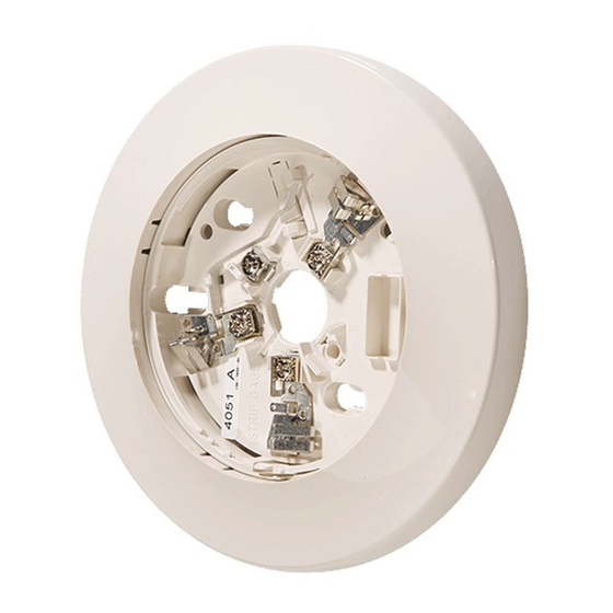
Mounting
The detector base mounts directly to 3-1/2 inch and 4-inch
octagon boxes and 4-inch square boxes, with or without
plaster rings. To mount the base, remove the decorative
ring by rotating it in either direction to unhook the snaps
before separating the ring from the base. Use the screws
supplied with the junction box to attach the base to the box
through the appropriate slots in the base (see Figure 1).
Position the decorative ring around the base and rotate it
in either direction until the ring snaps into place.
Installation Guidelines
Allowable loop resistance is an important specification for
control panels as well as for smoke detectors and their
bases. The alarm system cannot be expected to oper-
1-800-SENSOR2, FAX: 905-812-0771
www.systemsensor.ca
I56-1028-000
Advertisement
Table of Contents

Subscribe to Our Youtube Channel
Related Manuals for System Sensor B110LPA


Summary of Contents for System Sensor B110LPA
- Page 1 Installation Guidelines General Description Allowable loop resistance is an important specification for The Model B110LPA detector base is designed for use with control panels as well as for smoke detectors and their bases. The alarm system cannot be expected to oper- D150-05-00...
- Page 2 Figure 1. Mounting base to box: allowable loop resistances.Therefore, before beginning installation, refer to the control panel manufacturer’s loop resistance specification to ensure that it is listed as com- patible with the System Sensor base and smoke detector being installed. Connect detectors only to ULC compatible control units. SNAP ON...
- Page 3 Figure 2. Wiring diagram for a typical 2-wire detector system: NOTE: IF A REMOTE AN- NUNCIATOR IS NOT USED, POLARITY OF THESE TERMINALS MAY BE REVERSED. REMOTE REMOTE ANNUNCIATOR ANNUNCIATOR A78-1175-04 CLASS A OPTIONAL WIRING Figure 3A. Activating the tamper-resistance feature: Figure 3B.
- Page 4 This is to ensure that both can detect a wide range Three-Year Limited Warranty System Sensor warrants its enclosed smoke detector base to be free partment, RA #__________, 6581 Kitimat Rd., Unit #6, Mississauga, ON, from defects in materials and workmanship under normal use and L5N 3T5.
Need help?
Do you have a question about the B110LPA and is the answer not in the manual?
Questions and answers