
Related Manuals for VORON SWITCHWIRE


Summary of Contents for VORON SWITCHWIRE
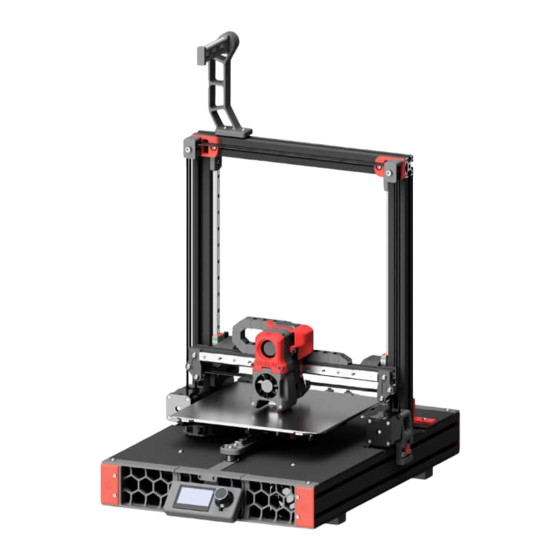
- Page 1 WWW.VORONDESIGN.COM VORON SWITCHWIRE ASSEMBLY MANUAL We build space shuttles with gardening tools so anyone can have a space shuttle of their own. VERSION 2021-11-26...
- Page 2 Please do not become the first VORON fatality. There is no special Reddit flair for that. Please, read the entire manual before you start assembly. As you begin wrenching, please check our Discord channels for any tips and questions that may halt your progress.
-
Page 3: Table Of Contents
TABLE OF CONTENTS WWW.VORONDESIGN.COM Introduction Hardware Frame Y Axis Skirts X&Z Axis X Carriage AfterBurner Electronics & Panels Wiring Finishing Touches... -
Page 4: Introduction
PART PRINTING GUIDELINES The Voron Team has provided the following print guidelines for you to follow in order to have the best chance at success with your parts. There are often questions about substituting materials or changing printing standards, but we recommend you follow these. - Page 5 If you need assistance with your build, we’re here to help. Head on over to our Discord group and post your questions. This is our primary medium to help VORON Users and we have a great community that can help you out if you get stuck.
-
Page 6: Hardware
SOCKET HEAD CAP SCREW (SHCS) Metric fastener with a cylindrical head PULLEY and hex drive. The most common GT2 pulley used on the motion system fastener used on the Voron. of the Voron. ISO 4762 HEX NUT SHIM Hex nuts couple with bolts to create a Not to be confused with stamped tight, secure joint. - Page 7 HARDWARE WWW.VORONDESIGN.COM POST INSTALL T-SLOT NUT F695 BEARING Nut that can be inserted into the slot of A ball bearing with a flange used in an aluminium profile. Used in various gantry locations. both M3 and M5 variants throughout this guide.
- Page 8 INTRODUCTION WWW.VORONDESIGN.COM BLIND JOINT BASICS Blind Joints provide a cost effective and rigid assembly method. The head of the BHCS is slid into the channel of another extrusion and securely fastened through a small access hole in the extrusion. https://voron.link/onjwmcd...
- Page 9 INTRODUCTION WWW.VORONDESIGN.COM BALL-END DRIVER Some parts of this design require the use of a ball-end hex driver for assembly. We recommend you get a 2.5mm and 3mm one. 2.5MM HEX DRIVER The 2.5mm hex driver will see a lot of use in this build.
- Page 10 FRAME WWW.VORONDESIGN.COM...
- Page 11 EXTRUSIONS WWW.VORONDESIGN.COM GETTING EXTRUSIONS TOGETHER Separate the extrusions you’re going to need for this section of the build. We’ve laid out all the parts you should have and highlighted the ones that will be used in the following sections.
-
Page 12: Frame
FRAME WWW.VORONDESIGN.COM M8x16 BHCS BLIND JOINT BASICS Blind Joints provide a cost effective and rigid assembly method. The head of the BHCS is slid into the channel of another extrusion and securely fastened through a small access hole in the other extrusion. - Page 13 8. If you’ve never assembled one before we recommend you watch the linked guide. https://voron.link/onjwmcd UPSIDE DOWN ASSEMBLY BUILD ON A FLAT SURFACE For ease of assembly we often recommend to Build the frame on a glass or granite surface assemble components upside down.
- Page 14 FRAME WWW.VORONDESIGN.COM M5x10 BHCS T-NUTS? We don’t show the insertion of T-Nuts in our assembly manuals. The T-Nuts we recommend can be inserted at any point during the installation.
- Page 15 FRAME WWW.VORONDESIGN.COM VERIFY DIMENSIONS Make sure the frame is square and that all positions are set correctly before moving on. Check the 90° angles with a machinist square. MIND ACCESS HOLE POSITION We do our best to call out things that may bite you later in the assembly process but may skip things that seem obvious to us.
- Page 16 FRAME WWW.VORONDESIGN.COM BUILD ON A FLAT SURFACE Build this section of the frame on a glass or granite surface to ensure you can get it as square as possible. M8x16 BHCS TILT FRAME 90° The access holes for the Blind Joints are at the bottom.
- Page 17 WWW.VORONDESIGN.COM VERIFY DIMENSIONS Check the corners and make sure that they are at 90° angles. Use a small machinist square. If you have the measuring equipment verify that both uprights are dead on parallel. Correct the angle is required. Failure in doing so may result in a sticky Z Axis.
- Page 18 Z RAILS WWW.VORONDESIGN.COM MIND THE CARRIAGE M5x10 BHCS The carriages are designed to slide along the rail easily. This unfortunately also includes sliding off the rails. Dropping the carriage likely irreparably damages it. NO STOPPER ON LEFT RAIL The left rail does not have a stopper in place to prevent the carriage from sliding off the rail.
- Page 19 WWW.VORONDESIGN.COM This page intentionally left blank.
- Page 20 Y AXIS WWW.VORONDESIGN.COM...
- Page 21 WWW.VORONDESIGN.COM ® FINISHED CARRIAGE LDO MOTORS Some vendors offer carriages with the bolt pattern required for the Voron Switchwire. If you sourced a premachined carriage you can skip this step. M3x8 SHCS CARRIAGE MODIFICATION If you sourced an unmodified carriage (e.g. a Prusa replacement part) you’ll need to modify the hole pattern.
- Page 22 Y IDLER WWW.VORONDESIGN.COM M5 Shim F695 Bearing DON’T OVER TIGHTEN The M5 screws are threaded directly into plastic. M5x30 BHCS The plastic part has threads modeled into it. UPSIDE DOWN ASSEMBLY Why fight gravity if it can work for us.
- Page 23 Y IDLER WWW.VORONDESIGN.COM M5x10 BHCS FULLY SEAT Make sure the part is installed flush against the extrusion.
- Page 24 Y MOTOR WWW.VORONDESIGN.COM GT2 20T Pulley GRUB SCREWS aka the root of all issues Use thread locker on all grub screws after you set their position. Loose grub screws account for the majority of issues that our users report. Save yourself hours of troubleshooting and apply thread locker to all grub screws during the build.
- Page 25 Y MOTOR WWW.VORONDESIGN.COM M3x30 SHCS M5x10 BHCS MOTOR ORIENTATION Rotate the motor in such a way that the connector/wires are on the left side when looking at it from the back.
-
Page 26: Y Axis
Y AXIS WWW.VORONDESIGN.COM M3x8 SHCS CENTERED RAIL INSTALLATION GUIDE Use the guides to position the rail in the center of the extrusion prior to fastening the bolts. - Page 27 DECK PANELS WWW.VORONDESIGN.COM ® PREMADE WIRE HARNESS LDO MOTORS If you sourced a premade wire harness add the cables that pass through the deck panels now. Heatbed Cables Toolhead Cables X Motor Cables Z Motor Cables DECK PANELS?! You can install the deck panels at this point if you like. We didn’t show them to make some captures easier.
- Page 28 DECK PANELS WWW.VORONDESIGN.COM M5x10 BHCS...
- Page 29 This design relies heavily on heat set inserts. Make sure you have the proper inserts (check the hardware reference for a close up picture). Heat Set Insert If you’ve never worked with heat set inserts before we recommend you watch the linked guide. https://voron.link/m5ybt4d...
- Page 30 Y BELT HOLDER - MICROSWITCH WWW.VORONDESIGN.COM Heat Set Insert M2x10 Self Tapping Microswitch SOLDER WIRES Solder approx. 100mm of wire to the mircoswitch before installing it. See setup guide for details.
- Page 31 Y CABLE CHAIN MOUNT WWW.VORONDESIGN.COM Heat Set Insert TRIANGLE PATTERN M5x10 BHCS ® IGUS PATTERN LDO MOTORS...
- Page 32 Y BELT PATH WWW.VORONDESIGN.COM GT2 Belt M3x12 SHCS WHERE’S THAT PRINTED PART? Look for asterix next to the part. It indicates that this is an accent part.
- Page 33 BED CARRIAGE INSTALLATION WWW.VORONDESIGN.COM M3x8 SHCS Prusa Style Bed Carriage...
- Page 34 Y BELT HOLDER WWW.VORONDESIGN.COM M3x30 SHCS...
- Page 35 Y CABLE CHAIN WWW.VORONDESIGN.COM CABLE CHAIN HOLE PATTERN Cable chains ends have a couple of different hole patterns. We offer mounts for both the inline pattern used on IGUS chains, and the triangle pattern present on budget chains. ® TRIANGLE PATTERN IGUS PATTERN LDO MOTORS Heat Set Insert...
- Page 36 WWW.VORONDESIGN.COM M3x8 SHCS...
- Page 37 WWW.VORONDESIGN.COM This page intentionally left blank.
- Page 38 SKIRTS WWW.VORONDESIGN.COM...
-
Page 39: Skirts
FRONT SKIRTS WWW.VORONDESIGN.COM Heat Set Insert M3x8 SHCS DON’T TIGHTEN Leave the bolts slightly loose for the next step. - Page 40 FRONT SKIRT WWW.VORONDESIGN.COM M3x8 SHCS M5x10 BHCS M3x8 SHCS TIGHTEN BOLTS Tighten the bolts that connect the centre piece once installed on the frame.
- Page 41 BACK SKIRT WWW.VORONDESIGN.COM Heat Set Insert M3x8 SHCS DON’T TIGHTEN Leave the bolts slightly loose for the next step.
- Page 42 BACK SKIRT WWW.VORONDESIGN.COM M3x8 SHCS TIGHTEN BOLTS Tighten the bolts that connect the centre piece once installed on the frame. M5x10 BHCS M3x8 SHCS...
- Page 43 WWW.VORONDESIGN.COM This page intentionally left blank.
- Page 44 X&Z AXIS WWW.VORONDESIGN.COM...
- Page 45 “Z” MOTOR MOUNT WWW.VORONDESIGN.COM GT2 20T Pulley M3x30 SHCS Heat Set Insert MOTOR ORIENTATION Make sure the motor is oriented as shown. M3x40 SHCS...
- Page 46 “Z” MOTOR MOUNT WWW.VORONDESIGN.COM M5x16 BHCS MOTOR MOUNT INSTALLATION Push the motor mount as far up as the slots in the parts allow you to before fastening the bolts. You may need to turn the M3x40 counter clock wise to fully bottom out in the slot.
- Page 47 “X” MOTOR MOUNT WWW.VORONDESIGN.COM GT2 20T Pulley M3x30 SHCS Heat Set Insert M3x40 SHCS MOTOR ORIENTATION Make sure the motor is oriented as shown.
- Page 48 “X” MOTOR MOUNT WWW.VORONDESIGN.COM M5x16 BHCS MOTOR MOUNT INSTALLATION Push the motor mount as far up as the slots in the parts allow you to before fastening the bolts. You may need to turn the M3x40 counter clock wise to fully bottom out in the slot.
- Page 49 LEFT IDLER WWW.VORONDESIGN.COM M5 Shim F695 Bearing M5x40 SHCS M5x10 BHCS...
- Page 50 RIGHT IDLER WWW.VORONDESIGN.COM M5 Shim F695 Bearing M5x40 SHCS M5x10 BHCS...
- Page 51 TOP IDLERS WWW.VORONDESIGN.COM CHECK ORIENTATION Make sure the cut-out is facing down.
- Page 52 XZ BLOCKS WWW.VORONDESIGN.COM M5 Shim UPSIDE DOWN ASSEMBLY We’ll flip these components a few times. F695 Bearing Pay attention to their final orientation M5x30 BHCS...
- Page 53 X AXIS WWW.VORONDESIGN.COM M3x8 SHCS CENTERED RAIL INSTALLATION GUIDE Use the guides to position the rail in the center of the extrusion prior to fastening the bolts. MGN12 Linear Rail M5x10 BHCS...
- Page 54 X AXIS WWW.VORONDESIGN.COM CHECK ORIENTATION Make sure the XZ joints are oriented correctly. The reliefed/cutout section points towards the front. The idlers towards the bottom.
- Page 55 Z BEARING BLOCK WWW.VORONDESIGN.COM Heat Set Insert M3x30 SHCS...
- Page 56 X AXIS WWW.VORONDESIGN.COM X AXIS INSTALLATION Lightly tighten the M5x40 bolts and align the X axis horizontally by moving it all the way to the top. Make sure it is centered across the front. M5x40 SHCS Hold the X axis against the stoppers and fully tighten the bolts.
- Page 57 WWW.VORONDESIGN.COM This page intentionally left blank.
- Page 58 X CARRIAGE WWW.VORONDESIGN.COM...
- Page 59 HEAT SETS WWW.VORONDESIGN.COM Heat Set Insert...
-
Page 60: Carriage
X CARRIAGE WWW.VORONDESIGN.COM M3 Nut Heat Set Insert... - Page 61 WWW.VORONDESIGN.COM M2x10 Self Tapping END-STOP SWITCHES FOR X AND Y Microswitch End-stops are wired in a “Normally Closed” configuration. On microswitches those are the 2 outer terminals indicated by C and NC. Prepare the switches for X by soldering 150mm of wire to each of the outer terminals.
- Page 62 X CARRIAGE WWW.VORONDESIGN.COM M3x12 SHCS M3x40 SHCS M3x16 SHCS SCREW DEPTH Don’t tighten the bolts all the way. Leave 3-4mm of exposed thread.
- Page 63 X CARRIAGE WWW.VORONDESIGN.COM PROBE WIRES Unless your probe comes preterminated cut the probes wires to about 15cm. Don’t cut them flush with the carriage frame. Inductive Probe ® OTHER PROBE TYPES LDO MOTORS The picture shows a PL-08 probe. The recommended Omron TL-Q5MC probe will fit in the same space but requires M3x25 SHCS.
- Page 64 X CARRIAGE PLATE WWW.VORONDESIGN.COM M3x8 SHCS...
- Page 65 X CARRIAGE WWW.VORONDESIGN.COM M3x12 SHCS...
- Page 66 BELT TENTIONER WWW.VORONDESIGN.COM BELT TENTIONER FOR “X” AND “Z” The motor mounts for the “X” and the “Z” motors have build in tentioners. ADJUSTMENT SCREW LOCK SCREWS Turn the screw clockwise to pull a higher tension Slightly loosen these screws before adjusting on the belt.
- Page 67 BELT PATH WWW.VORONDESIGN.COM BELT POSITION Adjust the position of the pulley if required. Heavy contact with the flanges will introduce artefacts into your prints. BELT PATH Take your time and make sure your belt routing is as intended. Belts should never rub on plastic parts.
- Page 68 “Z” BELT WWW.VORONDESIGN.COM...
- Page 69 “X” BELT WWW.VORONDESIGN.COM...
- Page 70 COUNTERWEIGHT MOUNT WWW.VORONDESIGN.COM WEAR EYE PROTECTION The Key-Bak will violently retract if you lose grip of the end piece. Wear eye protection or a face shield until it is securely mounted. Key-Bak Super 48 Heat Set Insert M5x10 SHCS RAIL CARRIAGE The rail carriage is now secure.
- Page 71 COUNTERWEIGHT IDLER WWW.VORONDESIGN.COM M5 Shim F695 Bearing M5x16 BHCS MOUNTING THE KEYBACK END PIECE Pull the end piece of the Key-Bak and mount it as shown. Extend more of the cord and hook it in the idler mounted above. M3x12 SHCS...
- Page 72 AFTERBURNER WWW.VORONDESIGN.COM...
- Page 73 TOOL CARTRIDGE WWW.VORONDESIGN.COM AVAILABLE MOUNTS We also provide mounts for the Slice Engineering Mosquito and TriangleLab/Phaetus Dragon Hotend. They are assembled in a similar manner. Heat Set Insert Heat Set Insert E3D V6 Style Hotend M3x16 SHCS M3x16 SHCS...
- Page 74 TOOL CARTRIDGE WWW.VORONDESIGN.COM PTFE Tube M3x40 SHCS PTFE STICKOUT The PTFE tube should end 10mm above the surface of the printed part.
- Page 75 TOOL CARTRIDGE WWW.VORONDESIGN.COM WIRING PATH Guide the wires in the highlighted path. CHECK ORIENTATION The heater block must point forwards.
- Page 76 TOOL CARTRIDGE WWW.VORONDESIGN.COM M3x40 SHCS DON’T TIGHTEN Don’t tighten the bolts all the way. The tool cartridge must be able to slip in and out.
- Page 77 CLOCKWORK WWW.VORONDESIGN.COM ® OPTION: TOOLHEAD PCB LDO MOTORS If you opt to use a toolhead pcb add an aditional heat set insert into the alternate part. HEAT SET INSERTS You will need to install heat set inserts into various plastic parts. If you need help on the correct procedure, ask in Discord.
- Page 78 CLOCKWORK WWW.VORONDESIGN.COM Heat Set Insert ® GENERIC CABLE CHAIN IGUS CABLE CHAIN LDO MOTORS The 3 hole pattern is usually IGUS chain have 2 mounting found on generic cable chains. holes.
- Page 79 CLOCKWORK WWW.VORONDESIGN.COM Het Set Insert...
- Page 80 CLOCKWORK WWW.VORONDESIGN.COM MOTOR ORIENTATION Rotate the motor in such a way that BMG Drive Pinion the connector/wires are on the left side when looking at it from the back. ALL UNITS ARE METRIC If a unit is not specified This side will be covered by the cable assume it’s metric.
- Page 81 CLOCKWORK WWW.VORONDESIGN.COM M3x8 SHCS ADJUSTABLE MOTOR POSITION The motor position is adjustable to allow for a proper meshing of the drive gears. Start in the top most position of the slot.
- Page 82 CLOCKWORK WWW.VORONDESIGN.COM CHECK BEARING FIT BMG Drive Gear The bearings must slip on and off the shaft easily to allow the gear to self centre. Do not shim into position. Pressing the bearings on the shaft will damage them. MR85 Bearing Lightly sand the shaft if required.
- Page 83 CLOCKWORK WWW.VORONDESIGN.COM M3x30 SHCS CHECK CLEARANCE The drive shaft must not touch the motor housing. You can sand the face of shaft if required.
- Page 84 CLOCKWORK WWW.VORONDESIGN.COM CHECK GEAR PLAY The gear should have a slight play and should should turn without any tight spots or binding. Adjust the position of the motor if required. See page 71.
- Page 85 CLOCKWORK WWW.VORONDESIGN.COM BMG Idler Assembly LUBRICATE BEARINGS A lubrication film is required to ensure smooth operation and longevity. Refer to the BOM for lubricant options.
- Page 86 GUIDLER & LATCH WWW.VORONDESIGN.COM M3x20 SHCS M3x30 SHCS...
- Page 87 CLOCKWORK WWW.VORONDESIGN.COM BMG Thumb Screw REMOVE BOLTS Carefully remove the bolts from the left side of the motor. They will be replaced with new bolts in the next step. M3x20 SHCS...
- Page 88 CLOCKWORK WWW.VORONDESIGN.COM ® OPTION: TOOLHEAD PCB LDO MOTORS If you opted to use a toolhead pcb skip this step. M3x8 SHCS...
- Page 89 CLOCKWORK WWW.VORONDESIGN.COM M3x20 SHCS M3x30 SHCS...
- Page 90 FAN ASSEMBLY WWW.VORONDESIGN.COM DON’T OVER TIGHTEN The screws are screwed directly into plastic. M3x16 SHCS REMOVE TOP COVER WIRING PATH Split the fan open by Route the wires through the large opening in the back. bending the tabs on the side.
- Page 91 FAN ASSEMBLY WWW.VORONDESIGN.COM AIRFLOW DIRECTION Piece of Filament Make sure the fan blows air towards the hotend. Look for a small arrow on the fan WIRING PATH housing. Guide the wires in the highlighted path.
- Page 92 FAN ASSEMBLY WWW.VORONDESIGN.COM M3x30 SHCS M3x12 SHCS...
- Page 93 WWW.VORONDESIGN.COM Toolhead PCB ® OPTION: TOOLHEAD PCB LDO MOTORS M3 Washer If you opted to use a toolhead pcb install it instead of the cable cover. M3x8 SHCS...
- Page 94 ELECTRONICS AND PANELS WWW.VORONDESIGN.COM...
- Page 95 MAINS INLET WWW.VORONDESIGN.COM Mains Inlet...
- Page 96 MAIN PSU WWW.VORONDESIGN.COM Meanwell LRS350-24 M4x8 BHCS M4x8 BHCS...
- Page 97 PI/SECONDARY PSU/CONTROL BOARD WWW.VORONDESIGN.COM RS25-05 PSU M2x10 Self Tapping SKR Mini E3 2.0 M3x8 SHCS Dunar’s Cursor M3x8 SHCS...
- Page 98 PSU INSTALLATION WWW.VORONDESIGN.COM M5x10 BHCS...
- Page 99 WAGO TERMINALS WWW.VORONDESIGN.COM M5x10 BHCS WAGO 221 Clamps ® OPTION: WAGO TERMINAL STRIP LDO MOTORS WAGO 221 series clamps can be used to simplify the mains wiring.
- Page 100 SECONDARY PSU/PI INSTALLATION WWW.VORONDESIGN.COM M5x10 BHCS M5x10 BHCS...
- Page 101 CONTROL BOARD & FAN INSTALLATION WWW.VORONDESIGN.COM APPLY VHB TAPE 3M VHB tape is a double sided adhesive tape. Other vendors have similar products that you can use as a substitute. M5x10 BHCS 6020 Fan...
- Page 102 DECK PANEL WWW.VORONDESIGN.COM DECK PANELS Unless you installed the panels earlier undo the 6 bolts on the bed carriage and remove the bed carriage to install the panels. M5x10 BHCS...
- Page 103 CABLE RACEWAYS WWW.VORONDESIGN.COM APPLY VHB TAPE VHB Tape is a double sided adhesive tape. ® OPTION: CABLE RACEWAYS LDO MOTORS Raceways help in keeping the electronics compartment organized and clutter free.
- Page 104 TOOLHEAD PCB BREAKOUT WWW.VORONDESIGN.COM APPLY VHB TAPE VHB Tape is a double sided adhesive tape. M2x10 Self Tapping ® OPTION: TOOLHEAD PCB BREAKOUT BOARD LDO MOTORS Some premade wiring harnesses come with a breakout board for the electronics compartment. If yours did install it now.
- Page 105 Z CHAIN MOUNT WWW.VORONDESIGN.COM ® TRIANLGE PATTERN IGUS PATTERN LDO MOTORS Heat Set Insert M5x16 BHCS...
- Page 106 Z CABLE CHAIN WWW.VORONDESIGN.COM M3x6 FHCS 10x11 Cable Chain M3x6 FHCS...
- Page 107 X CABLE CHAIN WWW.VORONDESIGN.COM 10x11 Cable Chain M3x6 FHCS...
- Page 108 Y CABLE CHAIN WWW.VORONDESIGN.COM M3x6 FHCS M3x6 FHCS 10x11 Cable Chain...
- Page 109 LCD THING WWW.VORONDESIGN.COM Heat Set Insert Mini12864 Display M3x12 SHCS...
- Page 110 LCD THING WWW.VORONDESIGN.COM...
- Page 111 WWW.VORONDESIGN.COM This page intentionally left blank.
- Page 112 WWW.VORONDESIGN.COM...
- Page 113 WWW.VORONDESIGN.COM INPUT VOLTAGE SWITCH Check the input voltage switch of the power supply. It is located in the highlighted area behind the metal mesh. Make sure the selection matches your local mains voltage. Refer to the Mean Well LRS-350 datasheet for possible settings.
- Page 114 WWW.VORONDESIGN.COM ATTACH 250MM OF WIRE Cables should be at least 0.75mm² (AWG18) or thicker depending on local regulations. MAINS INLET WIRING We show the wiring in the IEC colour scheme. Depending on your region the colour scheme and wiring standards will differ. Mains wiring should only be done by qualified personnel trained in local regulations and safety standards.
- Page 115 MAINS WIRING WWW.VORONDESIGN.COM MAINS WIRING CONTINUED Secure the wires with cable clips / cable tie anchors. Observe your local regulations in regards to grounding the frame/other components.
- Page 116 MAINS WIRING - WAGO TERMINALS WWW.VORONDESIGN.COM ® MAINS WIRING CONTINUED LDO MOTORS Some vendors provide preprovisioned mains wiring components along. Observe your local regulations in regards to grounding the frame/other components.
- Page 117 DC POWER WWW.VORONDESIGN.COM 5V Raspberry Pi 24V Controller Board CABLE CROSS SECTION Cables to the controller board should be 2.5mm² (AWG14) or larger. 0.5mm² (AWG20) is sufficient for the connection to the Raspberry Pi.
- Page 118 DC POWER WWW.VORONDESIGN.COM 5V PSU RASPBERRY PI POWER While we suggest that you power the Raspberry Pi via the GPIO pins you may also power it using the “Power-In” USB port. Cut a suitable USB cable and wire the + and ground lines to the 5V PSU instead.
- Page 119 DC POWER WWW.VORONDESIGN.COM CONTROLLER BOARD The assembly manual will outline the wiring for a BTT SKR Mini E3 2.0. You can find additional documentation and alternative configurations on docs.vorondesign.com 24V PSU...
- Page 120 DC POWER - PREMADE CABLES WWW.VORONDESIGN.COM ® LDO MOTORS PREMADE CABLES Uptis velicatur sequam sunte voloresed magnisit inihit, ommodicia vit ad quis maio. PWR IN...
-
Page 121: Wiring
TOOLHEAD WIRING WWW.VORONDESIGN.COM HOTEND COOLING FAN 2x 0.25mm²(AWG24) or larger PART COOLING FAN 2x 0.25mm²(AWG24) or larger EXTRUDER MOTOR 4x 0.25mm²(AWG24) or larger ® LDO MOTORS HOTEND HEATER OPTION: TOOLHEAD PCB 2x 0.5mm²(AWG20) or larger If you are planing to use a toolhead PCB skip forward to the toolhead PCB section. - Page 122 CONTROLLER WIRING WWW.VORONDESIGN.COM HOTEND FAN 2x 0.25mm²(AWG24) or larger HOTEND HEATER 2x 0.5mm²(AWG20) or larger PART FAN X ENDSTOP 2x 0.25mm²(AWG24) or larger BAT85 DIODE INDUCTIVE PROBE Take special note of the black 3x 0.25mm²(AWG24) or larger band on the diode. It should be facing the probe as per the diagram.
- Page 123 HOTEND THERMISTOR X ENDSTOP PART COOLING FAN ® OPTION: TOOLHEAD PCB LDO MOTORS The layout of the toolhead pcb changed over HOTEND COOLING FAN the versions. For a full breakdown visit the link below. HOTEND HEATER PROBE https://voron.link/zopduze EXTRUDER MOTOR...
- Page 124 TOOLHEAD WIRING - TOOLHEAD PCB WWW.VORONDESIGN.COM ® LDO MOTORS...
- Page 125 CONTROLLER WIRING - TOOLHEAD PCB WWW.VORONDESIGN.COM ® LDO MOTORS BREAKOUT BOARD WIRING Breakout boards usually come with premade wires for hookup to the controller board. HOTEND THERMISTOR HOTEND CFAN + LED PROBE...
- Page 126 WWW.VORONDESIGN.COM CONTROLLER WIRING - TOOLHEAD PCB ® LDO MOTORS STEPPER E ENDSTOP X PART FAN HOTEND FAN Controller Fan...
- Page 127 CONTROLLER WIRING WWW.VORONDESIGN.COM MOTOR CONNECTIONS 4x 0.25mm²(AWG24) or larger BED HEATER 2x 1mm²(AWG18) or larger Y ENDSTOP 2x 0.25mm²(AWG24) or larger BED THERMISTOR 2x 0.25mm²(AWG24) or larger...
- Page 128 WWW.VORONDESIGN.COM SKR Mini Screen Adapter EXP 1 EXP 2...
- Page 129 WWW.VORONDESIGN.COM...
- Page 130 BOTTOM PANEL WWW.VORONDESIGN.COM M5x16 BHCS...
- Page 131 WWW.VORONDESIGN.COM...
- Page 132 FINAL TOUCHES WWW.VORONDESIGN.COM...
- Page 133 SPOOL HOLDER WWW.VORONDESIGN.COM Piece of PTFE Tube M5x16 BHCS...
- Page 134 HEATED BED WWW.VORONDESIGN.COM 6x6x3 Spacer Prusa MK52 Style Heated Bed M3x12 FHCS...
- Page 135 HEATED BED WWW.VORONDESIGN.COM Controller M3x8 Low Profile Ring Terminal BED HEATER WIRING Attach the cables for the bed heater from the sides. Use low M3 Nut profile bolts to secure the ring terminals to the heater.
- Page 136 HEATED BED WWW.VORONDESIGN.COM Flex Sheet...
- Page 137 CABLE COVER WWW.VORONDESIGN.COM M3x8 SHCS...
- Page 138 WWW.VORONDESIGN.COM...
- Page 139 If you need assistance with your build, we’re here to help. Head on over to our Discord group and post your questions. This is our primary medium to help VORON Users and we have a great community that can help you out if you get stuck.
- Page 140 WWW.VORONDESIGN.COM VORON Discord Website Github https://github.com/ https://discord.gg/voron vorondesign www.vorondesign.com...
- Page 141 WWW.VORONDESIGN.COM...
Need help?
Do you have a question about the SWITCHWIRE and is the answer not in the manual?
Questions and answers