
Related Manuals for VORON 2.4


Summary of Contents for VORON 2.4
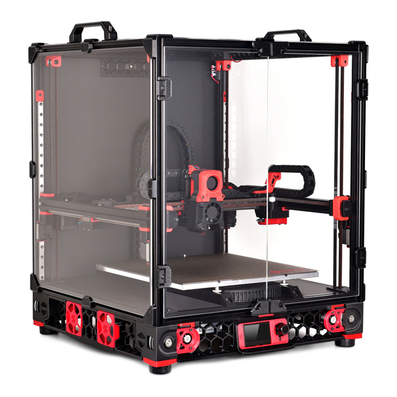
- Page 1 VORONDESIGN.COM VORON 2.4 ASSEMBLY MANUAL We build space shuttles with gardening tools so anyone can have a space shuttle of their own VERSION 2020.12.09...
-
Page 2: Table Of Contents
TABLE OF CONTENTS VORONDESIGN.COM VORON 2.4 Introduction LCD Module Skirts Frame Assembly Z Drive Panels Build Plate Spool Holder AB Drive Modules Exhaust Filter Gantry Electronics Mounting Wiring Afterburner Pre-Flight Checklist Belting Z Drive... - Page 3 Please do not become the first VORON fatality. There is no special Reddit flair for that. Please, read the entire manual before you start assembly. As you begin wrenching, please check our Discord channels for any tips and questions that may halt your progress.
-
Page 4: Introduction
INTRODUCTION STL FILE KEY By this time you should have already downloaded our STL files from the Voron GitHub. You might have noticed that we have used a unique naming convention for the files. This is how to use them. - Page 5 PRINT GUIDELINES The Voron Team has provided the following print guidelines for you to follow in order to have the best chance at success with your parts. There are often questions about substituting materials or changing printing standards, but we recommend you follow these recommendations as closely as possible.
- Page 6 If you need assistance with your build, we’re here to help. Head on over to our Discord group and post your questions. This is our primary medium to help VORON Users and we have a great community that can help you out if you get stuck.
- Page 7 FINAL THOUGHTS VORON printers are amazing machines that take care and attention to assemble. Take your time! Little issues in the assembly phase tend to stack up and cause you trouble later on. If at any point you get stuck or are just not sure about something, please ask on Discord. There are no stupid questions and we’re more than happy to point you in the right direction.
- Page 8 SOCKET HEAD CAP SCREW (SHCS) GT2 pulley used on the motion system of Metric fastener with a cylindrical head the Voron. Used in two sizes for both 6mm and hex drive. The Most common fastener and 9mm belt locations. used on the Voron.
- Page 9 GRUB SCREW 625 BEARING F695 BEARING Used to secure pulleys to stepper motor A ball bearing used on the Voron Z drives. A thinner ball bearing with a flange used in drive shafts. Take care to tighten these various gantry locations.
- Page 10 VORONDESIGN.COM FRAME...
- Page 11 VORONDESIGN.COM GATHERING EXTRUSIONS GETTING EXTRUSIONS TOGETHER Separate the extrusions you’re going to need for this section of the build. We’ve laid out all the parts you should have and highlighted the ones that will be used in the following sections.
- Page 12 VORONDESIGN.COM ASSEMBLE FIRST CORNER M5X16 BHCS Use a low strength thread lock compound here.
- Page 13 VORONDESIGN.COM ATTACHING MIRROR SIDE BUILDING SQUARE It’ not a bad idea to build this frame on a glass surface to ensure you can get it as square as possible.
- Page 14 VORONDESIGN.COM ASSEMBLE FRAME TOP CHECK THE FRAME Use a framing square and ensure all corners are as square as possible before moving on or you may have problems later on when you start printing.
- Page 15 VORONDESIGN.COM BED EXTRUSIONS M5 Shim M5X10 BHCS M5X16 BHCS FASTENERS Insert fasteners before you start. It makes attaching the bed extrusions to the frame easier. Don’t tighten these down too hard at this stage. We’ll want them loose when we install the heated bed assembly!
- Page 16 VORONDESIGN.COM Z AXIS LINEAR RAILS M3X8 SHCS CENTERED RAIL INSTALLATION GUIDE When tightening the fasteners to hold the linear rails in place, ensure that you have attached a centered rail installation guide to both the top and bottom. You should have two printed. DON’T OVER TIGHTEN! The M3 fasteners that hold the linear rails to the frame do not need to be hulked down.
- Page 17 VORONDESIGN.COM This page intentionally left blank.
- Page 18 VORONDESIGN.COM Z DRIVE ASSEMBLY...
- Page 19 VORONDESIGN.COM Z BELT DRIVE & STEPPER APPLY THREAD LOCK COMPOUND Make sure to apply thread lock compound to the grub screws. INSTALL HEAT SET INSERTS You will need to install heat set inserts into all four sets of Z drive housings. If you need help on the correct procedure, ask in Discord.
- Page 20 VORONDESIGN.COM BELT DRIVE SHAFT ASSEMBLY GT2 80T Pulley APPLY THREAD LOCK COMPOUND Make sure to apply thread lock compound not only to the 9mm pulley grub screws, but also the 80T pulley! M5 Shim 625 Bearing 625 Bearing 625 Bearing GT2 20T 9MM Pulley...
-
Page 21: Z Drive
VORONDESIGN.COM BELT DRIVE MODULES INSTALL HEAT SET INSERTS Don’t forget these ones on the bottom of each Z drive! M3x40 SHCS ASSEMBLE BELT DRIVE All four go together the same way. Don’t forget to put the belt loop on! - Page 22 VORONDESIGN.COM COMPRESSOR FEET M5 Hex Nut M5x10 BHCS M3x8 SHCS...
- Page 23 VORONDESIGN.COM Z DRIVE MOTOR MOUNTS M3X8 SHCS Attach Motor Mounts Attach all 4 motor mounts to their stepper motors for your Z drive. You will need M3x8 SHCS for these.
- Page 24 DECK SANDWICH VORONDESIGN.COM THE SANDWICH The bottom deck panel is held in place by mounting it in between the DIN rails and bed extrusions using M5 fasteners. Depending on the thickness of your panel you may need to use a washer so that the fasteners do not bottom out into the extrusions.
- Page 25 VORONDESIGN.COM DECK PANEL & Z DRIVES M5x40 SHCS INSTALL BOTTOM DECK PANEL Flip the frame over and install the deck panel. We’re going to be working inverted for a little bit. You probably want to tape the carriages in place so they don’t fall off the ends of the rails when you flip the machine!
- Page 26 VORONDESIGN.COM MOTOR INSTALL & BELTS M5x10 BHCS M5x10 BHCS Mounting Motors to Frame LIGHTLY secure the motor assemblies to the frame using the M5 fastener. We have more steps before we can fully tighten these.
- Page 27 VORONDESIGN.COM MOTOR TENSION Tighten M5 Bolts After closing the tensioner we can now tighten the M5 Bolts to secure the motor assembly. Close Belt Tensioner Flip the belt tensioner latch closed. It should sit flush with the frame.
- Page 28 VORONDESIGN.COM Z IDLERS M3 Hex Nut M5x30 BHCS GT2 20T 9mm Idler M3x16 SHCS...
- Page 29 VORONDESIGN.COM Z IDLERS FRAME INSTALL M5x30 BHCS...
- Page 30 VORONDESIGN.COM BUILD PLATE...
- Page 31 VORONDESIGN.COM HEATER & THERMAL FUSE Keenovo Heater Thermal Fuse...
- Page 32 VORONDESIGN.COM Z ENDSTOP PIN 33mm Shaft Deflange GT2 20T Check our help videos in discord if you need help removing the flange for the 20T pulley. Grub Screw...
-
Page 33: Gantry
VORONDESIGN.COM IMPORTANT NOTICE We have specified a notch to be cut into the Z endstop pin along with a grub screw. This is simply to prevent it from falling out if you tilt your machine to do work on it in the future. This does happen (even to the best of us) and can result in a nozzle strike with significant damage to the gantry. - Page 34 VORONDESIGN.COM Z ENDSTOP PIN Solder Connector It’s possible to solder the JST connector directly to the microswitch if you wish. M3x20 SHCS JST 3 Pin Connector Endstop Microswitch Secure the microswitch with two your M2 self tapping screws. Make sure to remove Microswitch the lever from the microswitch as it will get in the way.
- Page 35 VORONDESIGN.COM BUILD PLATE INSTALL M3x16 SHCS 3 POINT BED MOUNTING M4 Knurled Nut Some people have more luck doing a 3 point bed mount. It can help prevent bed warping.
- Page 36 VORONDESIGN.COM Z ENDSTOP INSTALL Z ENDSTOP POSITION The endstop is meant to fit under the build plate, but please make sure that the pin is not touching the bed. It can transfer heat giving inconsistent results in Z probing.
- Page 37 VORONDESIGN.COM This page intentionally left blank.
- Page 38 VORONDESIGN.COM AB DRIVE MODULES...
- Page 39 VORONDESIGN.COM FRONT IDLER HEAT SETS INSTALL HEAT SET INSERTS You will need to install heat set inserts into both Front Idler Tensioners. If you need help on the correct procedure, ask in Discord.
- Page 40 VORONDESIGN.COM FRONT IDLER ASSEMBLY M3 HOLE The bearing stack can be a little tricky to install. Sometimes it helps to use M5 Shim F695 Bearing the M5x40 as a guide and feed the washers and bearings in one at a time. M5x40 SHCS BEARING STACK The bearing stack can...
- Page 41 VORONDESIGN.COM AB BEARING STACKS M5 Shim F695 Bearing F695 Bearing M5 Shim 2x M5 Shim F695 Bearing F695 Bearing F695 Bearing F695 Bearing M5 Shim M5 Shim M5x30 BHCS M5x30 BHCS...
- Page 42 VORONDESIGN.COM B DRIVE MODULE UPSIDE DOWN It’s easier to build these upside down. Feed the M3 and M5 bolts through the top, flip it over and start building your bearing stacks. M3x30 SHCS...
- Page 43 VORONDESIGN.COM A DRIVE MODULE + CHAIN ANCHOR M3 Nut M3x30 SHCS CHAIN MOUNT This part will not stay in place unless the cable chain mount is attached. You may wish to add this part now or skip this step until you’re ready to add the cable chains.
- Page 44 VORONDESIGN.COM AB DRIVE STEPPER INSTALL APPLY THREAD LOCK COMPOUND Make sure to apply thread lock compound M3x30 SHCS to the pulley grub screws. GT2 20T Pulley...
- Page 45 VORONDESIGN.COM COMPLETED AB DRIVE UNITS M3x30 SHCS Heat Set Inserts M3x12 SHCS CHECK 20T PULLEY Make sure you mounted your 20T pulley on your A drive (right side image) opposite to the way we did the B drive (left side image).
- Page 46 VORONDESIGN.COM...
- Page 47 VORONDESIGN.COM DUAL RAIL INSTALL M3x8 SHCS CENTERED RAIL INSTALLATION GUIDE When tightening the fasteners to hold the linear rails in place, ensure that you have attached a centered rail installation guide to both the top and bottom. You should have two printed.
- Page 48 VORONDESIGN.COM LEFT XY JOINT ASSEMBLY M5x40 SHCS GT2 20T Idler BEARING STACKS See previous examples for how to assemble these. We use the same bearings and fasteners as used in M5x40 SHCS M5 Hex Nut other steps.
- Page 49 VORONDESIGN.COM RIGHT XY JOINT ASSEMBLY GT2 20T Idler BEARING STACKS See previous examples for how to assemble these. We use the same bearings and fasteners as used in other M5 Hex Nut steps. M5x40 SHCS...
- Page 50 VORONDESIGN.COM MICROSWITCH POD Heat Set Inserts Microswitch M2x10 Self Tapping...
- Page 51 VORONDESIGN.COM XY BLOCK INSTALL M5x10 BHCS M5x16 BHCS M5x30 BHCS M5x30 BHCS...
- Page 52 VORONDESIGN.COM Y RAIL INSTALL M3x8 SHCS INSTALLING Y LINEAR RAILS The front idlers are our index point for the Y rail installation. Confirm that both idlers are sitting flush with the end of the extrusion and then install the linear rails such that they are pressed firmly against the backs of the idlers.
- Page 53 VORONDESIGN.COM FRONT IDLERS M5x16 BHCS M5x16 BHCS LEFT IDLER FLUSH INSTALL Make sure you mounted your 20T We are going to be indexing things off the front pulley on your A drive (right side idlers moving forward. Take your time and ensure image) opposite to the way we did that both idlers are sitting flush to the end of both the B drive (left side image).
- Page 54 VORONDESIGN.COM ATTACH AB MODULES INSTALLING AB DRIVE UNITS With your front idlers and linear rails on your Y extrusions, now we can install the AB Drive Units. Press these against the linear rail and secure from the top as per the diagram. M5x16 BHCS...
- Page 55 VORONDESIGN.COM REAR BRACE REAR BRACE EXTRUSION When you install your M5x10 BHCS fasteners, leave the back brace slightly loose. You want this to be able to move in later steps, but don’t leave it such that it will pull apart as we’re working on it. M5x10 BHCS...
- Page 56 VORONDESIGN.COM XY JOINTS M3x16 SHCS M3x16 SHCS...
- Page 57 VORONDESIGN.COM ENDSTOP MODULE Microswitch Pod M3x30 SHCS...
- Page 58 VORONDESIGN.COM AFTERBURNER...
- Page 59 VORONDESIGN.COM CARRIAGE M3x30 SHCS M3 Hex Nut M3x30 SHCS M3 Hex Nut Heat Sets...
- Page 60 VORONDESIGN.COM PROBE & PIVOT BLOCK Heat Set M3x20 SHCS...
- Page 61 VORONDESIGN.COM XY BELT RETENTION M3x12 SHCS Heat Set...
- Page 62 VORONDESIGN.COM CARRIAGE MOUNTING M3x8 SHCS BUTTON HEAD OPTION If you happen to have some M3x8 BHCS laying around you can use those here. It can make belting the gantry in later steps a little easier but it’s not a big deal if you don’t have them.
- Page 63 VORONDESIGN.COM PIVOT BLOCK M3 Nut M3x8 SHCS M3x30 SHCS DO NOT TIGHTEN (YET) Leave these loose. You’ll need to aslign the rail before tightening. See discord if you need help with the correct procedure.
- Page 64 VORONDESIGN.COM A BELT ROUTING CUTTING BELTS Best practice is to cut both XY belts the same length. You can pre-run one length and then cut the other using it as your guide.
- Page 65 VORONDESIGN.COM B BELT ROUTING SECURING BELTS Pick one side of the carriage and tighten the belts down flush with the front face. This allows you to pull the belts on the other side an equal length to help keep things square.
- Page 66 VORONDESIGN.COM HOT END & FAN HOUSING M3x16 SHCS Heat Set M3x40 SHCS...
- Page 67 VORONDESIGN.COM HOT END RETENTION TEST FIT HOUSING Make sure to test fit the hot end housing. It should be able to slide in with firm pressure but not be loose enough that it can wobble. M3x16 SHCS...
- Page 68 VORONDESIGN.COM CLOCKWORK HEAT SETS...
- Page 69 VORONDESIGN.COM EXTRUDER LATCH Heat Set Needle Bearings Tension Knob Extruder Idler...
- Page 70 VORONDESIGN.COM CLOCKWORK STEPPER GEAR ENGAGEMENT You can adjust the engagement of the gears by leaving the M3X8 fastener slightly loose. Once these run smoothly you can tighten that down. MR85 Bearing M3x8 SHCS...
- Page 71 VORONDESIGN.COM CLOCKWORK HOUSING M3x30 SHCS...
- Page 72 VORONDESIGN.COM COOLING FANS SEPERATE BLOWER HOUSING You will have to remove the front of the blower housing before install. You can do this easily by prying the tabs up gently that hold it in place. 1.75MM Filament...
- Page 73 VORONDESIGN.COM FAN ASSEMBLY M3x16 SHCS M3x20 SHCS M3x30 SHCS M3x30 SHCS...
- Page 74 VORONDESIGN.COM MOUNTING FAN HOUSING M3x30 SHCS...
- Page 75 VORONDESIGN.COM CABLE CHAIN MOUNT Heat Set Inserts SWAP FASTENERS You will be swapping the fasteners that come with the stepper motor in the spots listed here. M3x20 SHCS...
- Page 76 VORONDESIGN.COM HOT END INSTALL Bowden Tube...
- Page 77 HOT END INSTALL 2 VORONDESIGN.COM M3x8 SHCS M3x12 SHCS...
- Page 78 VORONDESIGN.COM BELTING Z DRIVE...
- Page 79 VORONDESIGN.COM Z JOINTS M5 Hex Nut M3x30 SHCS M5x40 SHCS M5x30 BHCS...
- Page 80 VORONDESIGN.COM BELT ROUTING...
- Page 81 VORONDESIGN.COM MOUTING Z BLOCKS TO CARRIAGES M3x20 SHCS...
- Page 82 VORONDESIGN.COM LCD MODULE...
- Page 83 VORONDESIGN.COM HEAT SET INSERTS Heat Set Inserts...
- Page 84 VORONDESIGN.COM SPACER AND MOUNTING M3x12 SHCS...
- Page 85 VORONDESIGN.COM LCD LATCH M3x8 SHCS M3x8 SHCS...
- Page 86 VORONDESIGN.COM SKIRTS...
- Page 87 VORONDESIGN.COM FILTERED MAINS INLET M3x8 SHCS...
- Page 88 VORONDESIGN.COM INLET & ROCKER SWITCH #4 X 3/8 FLAT HEAD SELF TAPPING...
- Page 89 VORONDESIGN.COM This page intentionally left blank.
- Page 90 VORONDESIGN.COM ELECTRONICS COOLING ASSEMBLY Heat Set Insert USE VHB TO SECURE FANS You should have VHB tape as part of your bill of materials. Use it to secure the fans to the bracket.
- Page 91 VORONDESIGN.COM MOUNTING ELECTRONICS COOLING M3x8 SHCS M5x10 SHCS M3x8 SHCS...
- Page 92 VORONDESIGN.COM SKIRT HEAT SETS Heat Set Inserts...
- Page 93 VORONDESIGN.COM Z DRIVE COVER M3x8 SHCS...
- Page 94 VORONDESIGN.COM PANELS...
- Page 95 VORONDESIGN.COM FRONT DOOR LATCHES M3x8 SHCS M3x8 SHCS Magnets...
- Page 96 VORONDESIGN.COM FRONT DOORS USE VHB TO ATTACH LATCHES You should have VHB tape as part of your bill of materials. Use it to secure the panel latches to the polycarb panels.
- Page 97 VORONDESIGN.COM TOP PANEL M3x8 SHCS FOAM TAPE Depending on the height of the foam tape between the panels and the frame, you will likely have to use larger sized clips depending on it’s thickness.
- Page 98 VORONDESIGN.COM SIDE & REAR PANELS...
- Page 99 VORONDESIGN.COM Z BELT COVERS M3x6 BHCS...
- Page 100 VORONDESIGN.COM BOTTOM PANEL HINGES Remember to place the hinges on the rear of the machine.
- Page 101 VORONDESIGN.COM This page intentionally left blank.
- Page 102 VORONDESIGN.COM SPOOL HOLDER...
- Page 103 VORONDESIGN.COM SPOOL HOLDER ASSEMBLY PTFE Insert...
- Page 104 VORONDESIGN.COM SPOOL & BOWDEN TUBE HOLDER M3x8 SHCS M5x16 BHCS...
- Page 105 VORONDESIGN.COM This page intentionally left blank.
- Page 106 VORONDESIGN.COM EXHAUST FILTER...
- Page 107 VORONDESIGN.COM HEAT SET LOCATIONS Heat Set Inserts...
- Page 108 VORONDESIGN.COM BSP & FAN MOUNTING BSP Adapter DRILL ADAPTER Bowden tube won’t fit though some BSP adapters depending on the source. You’ll have to drill these out. M3x30 SHCS...
- Page 109 VORONDESIGN.COM FILTER INSTALL M3x8 SHCS...
- Page 110 VORONDESIGN.COM FILTER HOUSING MOUNTING BSP Adapter M5x10 BHCS M3x12 SHCS...
- Page 111 VORONDESIGN.COM PTFE ROUTING...
- Page 112 VORONDESIGN.COM ELECTRONICS MOUNTING 24V Power Supply BigTreeTech SKR BigTreeTech SKR Solid State Relay Raspberry Pi 5V Power Supply...
- Page 113 VORONDESIGN.COM SKR MOUNTING BRACKET M2x10 Self Tapping M3x8 SHCS...
- Page 114 VORONDESIGN.COM RASPBERRY PI MOUNTING M2x8 Self Tapping M2x10 Self Tapping M2x10 Self Tapping...
- Page 115 VORONDESIGN.COM POWER SUPPLY MOUNTING M3x8 SHCS M4x6 BHCS...
- Page 116 VORONDESIGN.COM SOLID STATE RELAY M4x6 BHCS...
- Page 117 VORONDESIGN.COM DIN MOUNTING ELECTRONICS...
- Page 118 VORONDESIGN.COM MAINS INLET WIRING You are about to start working with electrical wiring that can cause 24V PSU - N serious injury or death. Mains power can kill, and it will hurt 24V PSU - L the entire time you’re dying from it. If in doubt we encourage you to ask questions.
- Page 119 VORONDESIGN.COM MAINS VOLTAGE WIRING CHECK SOLID STATE RELAY TERMINALS Under no circumstances should you wire mains current to the low voltage side of the relay. Please consult manufacturers relevant documentation if you are the slightest bit unsure of where to connect wiring. CHECK VENDOR SPECS This wiring diagram is based on the current...
- Page 120 VORONDESIGN.COM LOW VOLTAGE POWER GPIO DIRECT POWER There are some risks to powering a Raspberry Pi directly to the GPIO. While it is very unlikely you would ever have a problem due to the protection circuit in the Meanwell power supply, you may elect to modify a USB cable to take advantage of the built in polyfuse.
-
Page 121: Wiring
VORONDESIGN.COM CONTROLLER WIRING The Voron printer supports multiple controller configurations. Depending on your choice, there will be different wiring requirements to follow. Please check our Discord for specific guides on the controller boards you have chosen. - Page 122 VORONDESIGN.COM CABLE CHAIN X AXIS M3x6 BHCS M3x6 BHCS...
- Page 123 VORONDESIGN.COM CABLE CHAIN Y AXIS M3x6 BHCS M3x6 BHCS...
- Page 124 VORONDESIGN.COM CABLE CHAIN Z AXIS M3x6 BHCS...
- Page 125 VORONDESIGN.COM CABLE CHAIN Z AXIS M3x12 SHCS M3 Hex Nut...
- Page 126 VORONDESIGN.COM Z MOTOR LOCATIONS Z MOTOR WIRING LOCATIONS A reference map of the motor locations when wiring based on the SKR MCU Z diagram.
- Page 127 VORONDESIGN.COM XY MOTOR LOCATIONS XY MOTOR WIRING LOCATIONS A reference map of the motor locations when wiring based on the SKR MCU diagram.
- Page 128 ENDSTOP WIRING WIRING ENDSTOPS For the purpose of endstops in the Voron - It is safer to wire in the NC configuration as a fault in the endstop or it’s wiring stalls mechanical movement in the machine and produces an error for the user to investigate.
-
Page 129: Pre-Flight Checklist
VORONDESIGN.COM PRE-FLIGHT CHECKLIST MAINS WIRING Now is a good time to go back and have a careful look at your mains wiring. Mistakes here can mean bad news so it’s best to get some fresh eyes on things. Verify that your wiring conforms to the previous guide steps. LOW VOLTAGE WIRING Double check that your low voltage wiring has been completed correctly. - Page 130 VORONDESIGN.COM VORON Website Github Discord www.vorondesign.com https://github.com/ https://discord.gg/xgXWctB...
- Page 131 VORONDESIGN.COM...
Need help?
Do you have a question about the 2.4 and is the answer not in the manual?
Questions and answers