Advertisement
Quick Links
Assembly Instructions
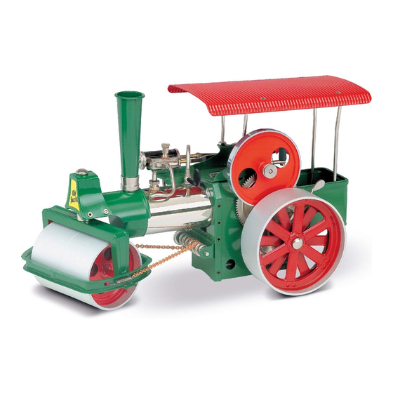
Steam Roller D375, D376, D377 & Traction Engine D415, D416, D417
Overview
Stage 1, Front Part
Stage 2, Burner Chamber Rear
Stage 3, Burner Chamber Front
Stage 4, Flywheel Shaft
Stage 5, Cylinder
1.
The assembly takes approx. 3-4 hours. Please allow sufficient time in order to avoid too many
interruptions.
2.
This is a valuable, demanding model. The assembly requires quiet, concentration and manual
dexterity.
3.
These instructions are applicable to both the steam engine as well as the traction engine. Please
refer to the relevant text/picture.
4.
The assembly should be carried out on a clean even table, so that no parts are lost.
5.
All parts have been checked several times and fit into each other. If something does not fit, do not
use force but study the assembly instructions/illustrations again.
6.
Before operating the steam engine, please read and observe the operating instructions carefully.
7.
After longer periods of operation, individual screws might need tightening.
Note: Brass and black/brass models. The brass parts are treated with a clear lacquer to prevent tarnishing.
After usage and to prevent tarnishing, apply a further coat of clear lacquer.
Text & illustrations: Wilesco Wilhelm Schröder GmbH & Co., Germany
Stage 6, Boiler Assembly
Stage 7, Burner, Front Connection Functioning of the original engine
Stage 8, Steering Mechanism
Stage 9, Rear Rollers
Stage 10, Roof and Chimney
Special Notes on the Assembly
Operating instructions
The Energy Transformation
History
Accessories
Advertisement

Related Manuals for Wilesco Steam Roller D375


Summary of Contents for Wilesco Steam Roller D375
- Page 1 Assembly Instructions Steam Roller D375, D376, D377 & Traction Engine D415, D416, D417 Overview Stage 1, Front Part Stage 6, Boiler Assembly Operating instructions Stage 2, Burner Chamber Rear Stage 7, Burner, Front Connection Functioning of the original engine Stage 3, Burner Chamber Front...
- Page 2 Assembly Instructions Steam Roller D375, D376, D377 & Traction Engine D415, D416, D417 Stage 1, Front Part Steam Roller Illustration 1 Illustration 2 2 x front rollers Push the two front rollers (1) onto the front axle (8). 1 x saddle cam...
- Page 3 The front axle (17) is pushed trough the wheel stage 8. assembly (16). The washers are fitted to both sides Text & illustrations: Wilesco Wilhelm Schröder GmbH & Co., Germany...
- Page 4 Assembly Instructions Steam Roller D375, D376, D377 & Traction Engine D415, D416, D417 Stage 2, Burner chamber, rear Illustration 5 Illustration 6 1x burner chamber cover Fit the tow bar (24) to the control cabin (21) with 2 1x control cabin slot bolts (4) M3x4mm and nuts (5).
- Page 5 Place front wall of chamber into position with 2 slot bolts (4) and nuts (5) and using the second and third hole from the bottom fix gangway bracket (30) through front cover onto burner chamber. Text & illustrations: Wilesco Wilhelm Schröder GmbH & Co., Germany...
- Page 6 Assembly Instructions Steam Roller D375, D376, D377 & Traction Engine D415, D416, D417 Stage 4, Flywheel shaft Illustration 11 Illustration 12 1 x machine plate This section must be assembled very carefully, as 1 x flywheel the functioning of the steam engine is dependent 1 x pulley on it.
- Page 7 (40). Illustration 15 Fit pulley (38) and tighten by means of the grub screw (39). Text & illustrations: Wilesco Wilhelm Schröder GmbH & Co., Germany...
- Page 8 Assembly Instructions Steam Roller D375, D376, D377 & Traction Engine D415, D416, D417 Stage 5, Cylinder Illustration 16 Illustration 17 1 x cylinder cap Push the slide valve (57) into the cylinder (55). 1 x cylinder complete Push on black cylinder casing (55) (nose 1 x seal diameter 5.5/2.5mm...
- Page 9 Assembly Instructions Steam Roller D375, D376, D377 & Traction Engine D415, D416, D417 Stage 6, Boiler Assembly Illustration 19 Illustration 20 1 x steam supply valve The large seal (69) is placed onto the spring loaded 1 x boiler safety valve (65). This is screwed into the boiler.
- Page 10 The oiler body (66) requires one seal (71) and is screwed into the top of cylinder. Then the oiler cap (67) is screwed in with a further seal (71). Text & illustrations: Wilesco Wilhelm Schröder GmbH & Co., Germany...
- Page 11 Assembly Instructions Steam Roller D375, D376, D377 & Traction Engine D415, D416, D417 Stage 7, Burner and Connection with cap or front part Illustration 24 Illustration 25 The burner guide (77) is placed into the burner 1 x burner slide chamber so that the four tabs pint downwards.
- Page 12 Illustration 27 Illustration 28 1 x steering column with pinion The steering column (81) is fitted with the short 1 x worm with chain and springs spacer (85) with the collar pointing upwards. Then 1 x safety cap diam. 4 mm it is pushed from underneath through the gangway 1 x steering wheel bracket and the steering bracket.
- Page 13 The photo (illustration 31a) shows the underneath of the traction engine. Place the springs of the steering chain from underneath into the small holes of the wheel bracket. The steering is complete now. Text & illustrations: Wilesco Wilhelm Schröder GmbH & Co., Germany...
- Page 14 Assembly Instructions Steam Roller D375, D376, D377 & Traction Engine D415, D416, D417 Stage 9, Rear Wheels Illustration 32 Illustration 33 2 x rear wheels The rear axle (92) is pushed through the burner 1 x rear axle diam. 5/142 mm chamber housing.
- Page 15 Assembly Instructions Steam Roller D375, D376, D377 & Traction Engine D415, D416, D417 Stage 10, Roof and chimney for Steam Roller Illustration 35 ONLY FOR STEAM ROLLER Illustration 35a ONLY FOR TRACTON ENGINES 1 x roof 1 x roof 1 x chimney 1 x chimney 1 x sticker "OLD SMOKY"...
- Page 16 Straighten out roof and tighten all nuts. Insert chimney (98/105) with fold pointing backwards. Stick the sticker "OLD SMOKY" (99) to the saddle cam of the steam roller. CONGRATULATIONS, YOU HAVE FINISHED! Text & illustrations: Wilesco Wilhelm Schröder GmbH & Co., Germany...
- Page 17 Any necessary repairs should only be carried out by trained staff, of at the WILESCO factory. The steam engine meets all safety standards and requirements. Every boiler has been submitted to a bursting pressure and water test of 5 bar (approx.
- Page 18 45! Pointing forwards (towards smoke stack). Now unscrew the oil filler screw and fill with WILESCO steam engine oil or car engine oil while turning the flywheel several times so that the oil is drawn in. Oil frequently so that the piston does not seize. 2-3 drops of oil are sufficient for approx.
- Page 19 Remote control is available for fitting to the steering wheel of the Steam Roller and Traction engine; the part no. is Z361 and can be ordered via your WILESCO retailer. Text & illustrations: Wilesco Wilhelm Schröder GmbH & Co., Germany...
- Page 20 The WILESCO-steam engines/traction engines work on the same principal as the old originals. However, instead of burning coal or coke a dry fuel tablet is used to heat the boiler.
- Page 21 Assembly Instructions Steam Roller D375, D376, D377 & Traction Engine D415, D416, D417 The Energy Transformation in the Cylinder The diagrams on the right show what actually happens inside the power converting system (piston and cylinder) when fire and water are...
- Page 22 Assembly Instructions Steam Roller D375, D376, D377 & Traction Engine D415, D416, D417 History of Steam Engines Approx. 1705 Papin/Newcomes built the first machine operated by steam. Approx. 1765 Watt built the first industrial steam engine. Approx. 1800 Use of steamships, steam locomotives, heavy goods vehicles, road rollers, fire engines and widely used in factories to drive machines.
- Page 23 Assembly Instructions Steam Roller D375, D376, D377 & Traction Engine D415, D416, D417 Accessories Illustration 39 Following items are included: 1 x screwdriver 1 x cylinder oil 1 x funnel 1 x dry fuel ESBIT 1 x combination spanner 1 x small spanner...
Need help?
Do you have a question about the Steam Roller D375 and is the answer not in the manual?
Questions and answers