Table of Contents
Advertisement
Advertisement
Table of Contents

Subscribe to Our Youtube Channel
Related Manuals for Dover markem-imaje 1050


Summary of Contents for Dover markem-imaje 1050
-
Page 3: Table Of Contents
Safety Instructions..............1 Introduction ................1 Key Features ..................1 Dynamic Data ..................2 Barcodes ....................2 InfiniteDPI ....................2 User Security and Reporting..............2 Advanced Text Options ................3 2.6.1 Flexible Text Formatting ................3 2.6.2 International Character Support ..............3 Overview of Menus ..............4 Home Screen..................4 Job Selection Screen................5 Tools Menu.....................6... - Page 4 Printing ..................38 Selecting a Job ..................38 Loading and Viewing External Data............38 Start/Pause Printing................41 Ink Levels .....................42 Printer Configuration ............... 43 10.1 Print Head Properties ................43 10.1.1 Distance from Sensor ................43 10.1.2 Print Direction ..................43 10.1.3 Stitching....................44 10.2 Encoder and Edges ................44 10.2.1 External Encoder ..................
-
Page 5: Safety Instructions
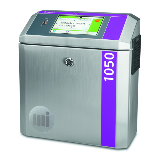
Read the Instruction Manual 2 Introduction The Markem-Imaje 1050 printer includes several high performance components that together create a flexible, accurate, high value platform for using HP® inkjet print technologies. With Markem-Imaje's complete print solutions, the highest quality printing can be achieved in all of our solutions. -
Page 6: Dynamic Data
2.2 Dynamic Data Data can be loaded from flat files or external databases to allow printing of dynamic data. The amount of data and the number of variable fields is limited only by memory. Timestamps, Shift codes and counters are available as well with flexible configurations to meet the most difficult requirements. -
Page 7: Advanced Text Options
2.6 Advanced Text Options 2.6.1 Flexible Text Formatting Advanced text formatting allows you to create the labeling you need, in any language. Key formatting features include: ▪ Use any True Type Font for text and barcodes ▪ Rotate text at any angle ▪... -
Page 8: Overview Of Menus
Overview of Menus 3.1 Home Screen Printer Fault/Warning Start/Pause Printing information Information printing status name Print Tools Data Source Profile Shut down Production preview button button information button button information ▪ Job name – displays the name of the job currently selected for printing. ▪... -
Page 9: Job Selection Screen
3.2 Job Selection Screen Press Scroll Selected for Selected arrows printing name Back Edit New Job Delete Select For Print button button button button Printing button preview ▪ Job Name – displays the name of the job currently selected for printing. ▪... -
Page 10: Tools Menu
3.3 Tools Menu Press Windows Print Functions Report Levels Profile Data Printer Configure Management Workflow Configuration The Tools menu provides access to the following menus. ▪ Ink Levels – provides information about the ink type and capacity. ▪ Log – provides operating history information. ▪... -
Page 11: Entering Text
3.4 Entering Text If a field requires text entry, press the field. The keyboard icon will appear. Press the keyboard icon and a soft keyboard will appear. Enter text. To view text that is obscured by the soft keyboard, press on the title bar, hold down, and drag the keyboard. -
Page 12: Layout Designer/Editor
4 Layout Designer/Editor ► ► For an existing job, press ► select desired job layout editor screen with job contents. ► ► ► For a new job, press configure pen layout settings new layout editor screen. See Creating a New Layout. Toolbar If the job is new, the layout editor will have no project loaded and most edit menus are disabled. -
Page 13: Dynamic Fields In A Layout
- Open Text Properties screen to add and format text - Add 1D, 2D, or postal barcode - Add bitmap image - Edit selected object settings - Copy, Paste, Cut, and Delete selected objects - Move all objects to visible area of layout - Close screen;... -
Page 14: Creating A New Layout
4.2 Creating a New Layout ► From the Home screen, press ► Or from the layout editor screen, press or File New… Any layout currently being edited should be saved or any edits will be lost. The Layout Settings window shown above will appear to allow the specification of the print layout. - Page 15 Release Note for Current Version In general, odd numbers of linked pens on a single print head with different horizontal resolutions is not supported. In this release, the second and third pens of any head cannot be linked unless the first and fourth are the same resolution. Any other combination is acceptable, for example four individual or two pairs (first and second and third and fourth) or all linked.
-
Page 16: Layout Designer Menus
4.3 Layout Designer Menus This section gives an overview of the menu items available. Detailed instructions follow in the appropriate sections. The File Menu has the basic file operations available. File ->New – creates a new layout and unloads any layout that is currently being edited. File ->Open –... -
Page 17: Creating Clocks, Timestamps, Shift Codes And User Inserts
4.4 Creating Clocks, Timestamps, Shift Codes and User Inserts 4.4.1 Clocks The Clocks dialog box is accessed via the Layout->Clocks menu item. Clocks are used to determine the time in creating timestamps and shift codes. If no offset is created, the clock represents the current time on the local system. -
Page 18: Timestamps
4.4.2 Timestamps Timestamps are added by selecting Layout->Timestamps. In the above figure, a timestamp called CurrentDateAndTime was created to display the Date and Time Appropriate for the current Locale (DTL). At the top of the screen is the clock selection for the current timestamp. In this case, the Default clock was chosen, which represents the current time. - Page 19 The above figure shows a new timestamp based on the 6HrsBefore clock created earlier in the example. The Alpha weekday timestamp string has been added. This maps the day of week (with Monday always being Day 1) to a string value that is printed. In this case, the strings chosen are A-G.
-
Page 20: Shift Codes
4.4.3 Shift Codes Shift codes are created by selecting Layout->Shift Codes. The figure above shows the Shift Codes dialog box. A Shift code called Group A Shift was created by selecting the New button. Initially, the Shift Code column is blank. The shifts called A, B, and C were added. -
Page 21: User Inserts
4.4.4 User Inserts The above window allows entry of user inserts. User inserts contain data that is entered by the operator when a print job is started. The Insert ID is the unique ID that is entered into layout objects. This ID (and its brackets) will be replaced at print time with the data entered by the operator. -
Page 22: Adding And Editing Objects In A Layout
Counters allow auto incrementing values to be included in layouts. Start Value – The value of the counter at print start. ● Increment - Added to the current value every time a new image is printed. This ● can be a negative number. Minimum, Maximum –... -
Page 23: Text Objects
TIP: For systems using a mouse, holding the CTRL key and clicking multiple objects will select the objects as well as any initially selected object. Pressing the DELETE key will delete all selected objects. Selecting the Edit->Undo will restore the last deleted object. Selecting Undo multiple times will undo multiple deletions. After one or more objects are selected, Cut or Copy (via the Edit menu or with the CTRL-X and CTRL-C keys) can be used on the selected objects. - Page 24 The figure above shows the Text Properties dialog box after editing. The text has been changed, a Data Field, a TimeStamp, a Shift Code and a User Insert has been added to the Text box. Carriage returns have been added between each object for clarity. In addition to modifying the contents of the text, the Text Properties dialog box allows the modification of its appearance.
- Page 25 that is in the box at print time if natural size is chosen. Care should be taken to ensure that the text will not overwrite other objects in the layout as the size will increase without any limit during printing. It is not possible to resize the text box on the layout when the Natural Size box is checked as the box will always be the size of the text within it.
-
Page 26: Barcodes
The data formatting tab allows formatting of dynamic field data when printing. This has no effect on text that is not loaded from data fields. 4.5.3 Barcodes Selecting the Barcode toolbar item or selecting Layout->Add Barcode will bring up a list of barcodes available for use. These include 1D, 2D and postal barcodes. Each barcode has different properties and requirements for characters that can be entered, checksum digits and other properties. - Page 27 Shown above is the Barcode Properties dialog box. The first tab, labeled Barcode, contains general options for barcode drawing. There are two options for module size. For larger barcodes, the barcode can be drawn to fit the bounding box. For best results and smaller barcodes, the module size of the barcode can be selected by selecting “Specify Module Size”.
- Page 28 Shown above is the Barcode Data tab of the Barcode Properties dialog box. The Code Data input box is where the data for the barcode is entered. This data will be encoded in the barcode itself. To the right of the barcode is a button with three dots on it. Selecting this button will bring up a list of available data fields, timestamps and shift codes.
- Page 29 The format characters are: Placeholder character Description Stands for the next data character of the input data Stands for all remaining data characters in the input & data Stands for the next check digit (use only if check digits will be computed) Switch to Subset A (used in: Code 128, EAN 128, UCC 128) Start- or stop character A (only in: CODABAR)
- Page 30 If the E character from the preceding table or the Translate Escape Sequences checkbox is selected, then the following escape sequences will be interpreted by the barcode renderer. Escape sequence Description Valid for Barcode Symbology Bell (alert) Backspace Form feed New Line Carriage Return Horizontal Tab...
- Page 31 MaxiCode, Data Matrix, \Ennnnnn Extended Channel Interpretation (ECI). QR-Code, PDF417, MicroPDF417, Aztec Code nnnnnn … 6 digit ECI number with leading zeros Used for defining the character set (code page) for the subsequent encoded data – see C.1 Special ECI identifiers for QR-Code \EB, \EE nesting ECIs.
-
Page 32: Bitmaps
In the General tab of the Barcodes Properties dialog box, location, and position can be set directly is desired. The general tab allows manual placement and sizing of the barcode. In addition, rotation of 0, 90, 180, and 270 degrees is available. Z order is the order of printing of the object, from lowest to highest. -
Page 33: Conditional Bitmaps
white in an image processing program before loading. This will allow more sophisticated modification of image properties. It is important to note that image processing programs are designed to correctly display images on the screen which has an equal horizontal and vertical resolution. If images appear stretched in the layout it is most likely because the horizontal and vertical resolutions do not match the print resolution for the layout and thus the image will appear stretched when printed. -
Page 34: Previewing A Layout
(Add) button allows adding all images from a directory as conditional images. All files are added so care should be taken not to include files other than valid bitmap images in the selected directory. The data field value will be set to the name (excluding the extension) of each file added. -
Page 35: Data Workflow
5 Data Workflow ► Press On the Tools menu, the “Data Workflow” button allows the configuration of the print operator workflow. This workflow definition will control how the print window is displayed to the print operator and what layout jobs and data can be configured by the operator. 5.1 Job Source Selection The first option for Workflow is selection of job source. -
Page 36: Data Source Selection
5.2 Data Source Selection The figure above shows the Data Source selection screen. Similar to the Job selection screen, data can be loaded from a local or 1050 Remote TCP interface. The possible options for local data are None (no data), Fixed data source (the same data is always loaded at print time), Operator Selected, shown selected above, (operator selects local flat file at print time), and Remote Database. -
Page 37: Remote Control
5.3 Remote Control The Remote Control tab is only enabled if either remote job or remote data is configured in the prior tabs. Currently, only the TCP/IP remote client is supported. Selecting the Configure button allows designation of IP address and port that the remote server will listen on. -
Page 38: Profile Management
6 Profile Management At system startup, the following screen will appear. Then the Home screen will appear. The features and access level available will depend on how Profile Management in the Tools menu is configured. The default access level after startup is “Operator.” To change the access level: ►... -
Page 39: Configuring Role-Based Security
6.1 Configuring Role-based Security ► Press Role-based security for the printer is configured from the Tools / Profile Management menu. User access and passwords are configured from this screen. 6.2 Roles Press (Edit Role) The screen above shows the Administrator role with all tasks that can be controlled via the Role Management window enabled. -
Page 40: Configure I/O
7 Configure I/O ► Press The Configure I/O screen allows specified events to trigger output relay actions. ▪ NC indicates No Change ▪ C indicates close the relay ▪ O indicates open the relay These will only have an effect if the Markem-Imaje I/O controller is included in your printer or you purchase the optional accessory box with an I/O controller included. -
Page 41: Windows Functions
8 Windows Functions ► Press The system drive (C:\ drive) is write-protected for system reliability. To make permanent changes to the operating system, disk protection must be disabled first (Disable Disk Protection and Reboot). After any changes are complete, disk protection must be re-enabled (Enable Disk Protection and Reboot) for system reliability. -
Page 42: Printing
9 Printing 9.1 Selecting a Job From the Home screen, press elect job from list ► press 9.2 Loading and Viewing External Data If the selected job requires data, the following screen will open. The Data button is available only if the Workflow settings allow operator selected data or a remote database (via ADO.NET) is specified. - Page 43 Press the (Data) button and the Load Data screen will open. When the settings are as desired, press the (Ok) button. After the data is loaded, the View Data tab will be displayed. If the data is loaded correctly, the data will be shown on the View Data screen.
- Page 44 The screen above shows the data for four fields loaded correctly. The record number is indicated in the left hand column. The data that will be loaded into [Field 1] on any object in a layout in the current job is listed here. Selecting “Print Selected Rows Only”...
-
Page 45: Start/Pause Printing
9.3 Start/Pause Printing The Start printing button starts printing of the selected job. The Pause printing button pauses printing of the selected job. -
Page 46: Ink Levels
9.4 Ink Levels ► Press On the Ink Levels screen are the properties of the attached pen cartridges and the estimated remaining ink levels. The type of cartridge affects the drop size which will affect the rate of ink usage estimation. The size (single use or various bulk sizes) can also be selected. -
Page 47: Printer Configuration
10 Printer Configuration ► Press 10.1 Print Head Properties The grid shows the heads and pens available in the current configuration. These are determined by what licenses are available for this printer, not what pens are physically connected to the printer. Sections of the job are assigned to the pens in the order in which they appear on this screen. -
Page 48: Stitching
10.1.3 Stitching The “Stitching” column shows the number of pixels that will be removed from the pen. The corresponding pixels in the pen will be blanked. For example, if pen 2 has a value of 10, then 10 pixels of what would have been on the top of the pen will no longer be available for that pen when printing. -
Page 49: Encoder Usage And Infinitedpi
10.2.2 Encoder Usage and InfiniteDPI Using an external positional encoder allows the print head to determine the precise speed and location of target materials. This allows precise printing on the substrate, creating high quality prints. The encoder positional accuracy is the most important aspect of printing outside of the physical attributes of the ink and substrate. -
Page 50: Upgrades
10.3 Upgrades 10.3.1 Firmware Upgrade Upgrading the firmware requires a valid firmware image from Markem-Imaje. The printer must be turned on and connected to the controller computer before beginning the process. After pressing the button, a valid firmware image must be selected to upload to the printer. -
Page 51: Advanced Properties
10.4 Advanced Properties On this tab, some advanced properties of each head configured can be made. The voltage and fire time can be set for each head. These values should be set according the ink used for printing. The pen fire voltage can be 5.0 to 13.2 volts and the pen fire time can be anywhere from 1.0 µs to 3.1 µs. -
Page 52: Images And Data
10.5 Images and Data This screen allows the configuration of the data mode for the printer. In Sequential mode, the printer takes data records one at a time and uses the data for each subsequent print record. For example, the first image for all pens uses data from the first available record, the second image the second set of data and so on. -
Page 53: Spitting
10.6 Spitting Spitting fills the nozzles on the head with ink. If spitting is turned on, it will always occur on the first print, regardless of the Spit timeout value. After that, it will only occur after the Spit timeout. Spit lines are the number of lines to print when the Spit timeout happens. -
Page 54: Print History
11 Print History ► Press The main reporting screen shows the print history for this printer. The left pane shows all jobs that have been printed. Selecting a job in the left pane will display the detailed print history in the right pane. The pieces per hour for short run times may be inaccurate due to rounding. -
Page 55: Setting Up A Printer
12 Setting up a Printer 12.1 Printer Components The printer consists of a controller with an integrated touch screen user interface and at least one print head. The printer can be configured with a variety of print heads and an optional bulk ink delivery system. Additional options such as a stand and alarm tower are also available. -
Page 56: Resolution And Barcodes
13 Resolution and Barcodes Printing barcodes requires paying special attention to the resolution of the printer, especially if barcodes are small. Barcodes require a specific ratio of dark and light sections to be read properly. Because the printer job has a particular resolution (for example, 300 DPI) the barcode light and dark sections must fall along the columns of dots for the resolution of printing selected. -
Page 57: Backing Up And Restoring Data
14 Backing Up and Restoring Data 1. Press ► 2. Press (Backup Data) or (Restore Data). The primary data drive is listed as “Drive1” in the RSIPrint.config file in the “C:\Program Files\RSI” directory. By default, this is the C drive. Drive2 is the automatic backup drive. -
Page 58: Troubleshooting The Printer
15 Troubleshooting the Printer TIP: The Ethernet cable must be plugged into the left Ethernet socket as you face the printer. Symptom Possible Cause Possible Solution Print Log “Printer not Printer not powered on Power on printer responding. Check to make sure the printer is connected and powered on.”... - Page 59 Encoder not connected or Verify the encoder settings configured incorrectly in the Printer configuration and check to make sure encoder wheel is connected and turning. The speed of the encoder should be greater than zero in the print window when printing. Edge sensor is not Verify edge sensor is connected or failed...
- Page 60 Direction of travel for pen The direction of travel for a not set correctly pen is the direction looking down at the top of the cartridge from the back (where the connector is located). The label of the cartridge should be facing away from you as you look at the top.
-
Page 61: Floor Space Plan
16 Floor Space Plan 16.1 Controller Drawings are not binding. Markem-Imaje reserve the right to alter specifications and design of the product at any time without giving prior notice. -
Page 62: Print Head
16.2 Print Head Bulk ink delivery system (optional) 12 to 36 in 304 to 914 mm Print head Note: If using the bulk ink delivery system, it must be installed 12 to 36 inches (304 to 914 mm) above the print head.
Need help?
Do you have a question about the markem-imaje 1050 and is the answer not in the manual?
Questions and answers
I need help with the amount of ink. I don’t know where to adjust it, and the head turns very greasy fast.
To prevent the print head from becoming greasy on a Dover 1050 printer, you can adjust the ink amount by reducing the pulse width. If you reduce the pulse width, you should increase the voltage to maintain the correct energy needed for the print head to fire properly. Adjusting these settings helps control ink output and can prevent excess ink buildup.
This answer is automatically generated
How do I print a code upside down and back to front on a markem 1050
To print a code upside down and back to front on a Markem-Imaje 1050 printer, use the rotation options in the Barcodes Properties dialog box. You can rotate the code by 180 degrees for upside-down printing. For back-to-front printing (mirror image), check for a mirror or flip option in the software settings. If not directly available, create a mirrored image of the code in your design software before sending it to the printer.
This answer is automatically generated