Table of Contents
Advertisement
Advertisement
Table of Contents
Troubleshooting

Related Manuals for Dover Markem-Imaje 5000 Series


Summary of Contents for Dover Markem-Imaje 5000 Series
- Page 1 o p e r a t i o n g u i d e...
- Page 3 To the best of our knowledge, the information contained in this guide was correct at the time of printing. However, continual enhancement of our products can result in some differences between the instructions represented in this guide and your coder. MARKEM, Touch Dry, and CimControl are registered trademarks of MARKEM Corporation.
- Page 4 0855849enf 6/08...
-
Page 5: Table Of Contents
TABLE OF CONTENTS SECTION 1 ..........1 General Information 1.0 Welcome to the Model 5200/5400 . - Page 6 TABLE OF CONTENTS SECTION 3 ..........33 Printing 1.0 Powering on the Coder .
-
Page 7: Section 1
SECTION 1 General Information Model 5200/5400 Operation Guide... -
Page 9: Welcome To The Model 5200/5400
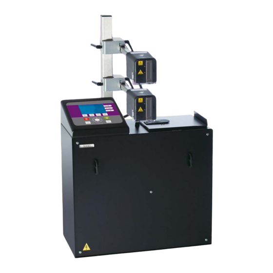
SECTION 1 GENERAL INFORMATION 1.0 Welcome to the Model 5200/5400 The Model 5200 and 5400 are part of the 5000 Series of case coders, which use MARKEM Touch Dry® ink technology, and provide flexibility and quality in coding cases directly on your packaging line. Depending on the ink delivery module of your coder, ink blocks or ink bottles are used. -
Page 10: Related Documentation
SECTION 1 GENERAL INFORMATION 1.2 Related Documentation This guide is part of a documentation set. Below is a list of documents in the Model 5200/5400 documentation set and their respective part numbers. • Model 5200/5400 Documentation Set ....0855847 •... -
Page 11: Before You Begin
SECTION 1 GENERAL INFORMATION 2.0 Before You Begin This guide makes a few assumptions. Before you can begin printing, make sure: • The coder is completely and correctly installed and integrated with your packaging line. If you do not know whether installation is complete, ask your company's setup technician. -
Page 12: Glossary
SECTION 1 GENERAL INFORMATION 3.0 Glossary allocation The maximum number of labels that the selected job will be allowed to print before the user is prompted to reset the allocation count or a new job is selected. array See jet array. backplane board Printed circuit board for I/O connections. - Page 13 SECTION 1 GENERAL INFORMATION field A specific manipulatable area within the job file. flash The process of writing the control software to nonvolatile memory. holding chamber The lower portion of the ink delivery module where ink is heated and stored. host computer The computer that contains the data that is downloaded to the coder.
- Page 14 SECTION 1 GENERAL INFORMATION package See product. print station The complete assembly consisting of the enclosure, electrical components, user interface module, and ink delivery module. product The material or item onto which the coder prints. Also called carton, case, package, or packaging. product ID reader A bar code reader that scans product information to determine which job file to print.
-
Page 15: Safety Information
SECTION 1 GENERAL INFORMATION 4.0 Safety Information The Model 5200/5400 has been designed to meet various safety standards. To alert you to potentially hazardous situations, labels and messages appear on the coder and throughout the guides. CAUTION refers to a potentially hazardous situation which, if not avoided, could result in personal injury. -
Page 16: Automatic Startup
SECTION 1 GENERAL INFORMATION 4.2 Automatic Startup CAUTION Do not allow an automatic packaging machine startup after a Model 5200/5400 reset. Install the Model 5200/5400 Status Output Signal Option for a manual packaging machine reset. Automatic startup of a packaging machine could kill or seriously maim an operator. TECHNICAL ISSUE: The Model 5200/5400 has an optional feature which enables it to stop or prevent packaging machine operation when coder conditions prevent marking the packages. -
Page 17: Safety Labels
SECTION 1 GENERAL INFORMATION 4.3 Safety Labels High Voltage To prevent injury from electrical shock, remove the power cord from the electrical outlet before performing troubleshooting or repair. Electronic troubleshooting must be performed by personnel trained to troubleshoot electrical circuits. Hot Surfaces To prevent injury from burns, be careful not to touch the jet array surface or hot ink directly. - Page 18 SECTION 1 GENERAL INFORMATION FRONT REAR 0855849enf 6/08...
-
Page 19: Foreseen Use
SECTION 1 GENERAL INFORMATION 4.5 Foreseen Use The Model 5200/5400 is an industrial case coder, designed for printing on substrates used in case and carton packaging, including coated and uncoated corrugated cardboard, glossy surfaces, rigid plastics, flexible films, and shrinkwrap. This coder was designed for or adapted by Markem-Imaje to a specific application at the time of sale. -
Page 20: Label And Symbol Identification
SECTION 1 GENERAL INFORMATION 5.0 Label and Symbol Identification Serial/I.D./Rating Label This label is located on the rear of the enclosure and indicates the following: Model number Information about the coder Information about Markem-Imaje Patents covered Serial number CE mark Electrical specifications Attention symbol Electrical diagram number... - Page 21 SECTION 1 GENERAL INFORMATION CE Mark This symbol indicates that the coder meets safety and environmental requirements as defined in the European Directives. ETL Listed This label indicates that the coder conforms to ANSI/UL Standard 60950 and is certified to Canada/CSA C22.2 Standard 60950. Status This symbol is located near the STATUS LED on the user interface module, and indicates whether or not the coder is ready to print.
- Page 22 SECTION 1 GENERAL INFORMATION Optional Control Unit (OCU) This symbol indicates the interface device port that is used for bar code readers or a product ID reader. Serial Port This symbol indicates the serial ports. I0I0I (1) - Host (RS232, RS422, and RS485) I0I0I (2) - ASCII Comms (RS232) I0I0I (3) - Not Used (RS232) Printhead...
-
Page 23: Removal From Service
SECTION 1 GENERAL INFORMATION 1.0 Removal from Service Follow these instructions to remove the coder from service. These instructions also pertain to transporting or storing the coder. Use the Shutdown menu to cool down and power off the coder. Disconnect the AC power cord from the electrical source. Disconnect cables and connections, accessed from the I/O door. -
Page 25: Section 2
SECTION 2 Basic Operation Model 5200/5400 Operation Guide... -
Page 27: Basic Components
SECTION 2 BASIC OPERATION 1.0 Basic Components The coder consists of the print station (1), umbilical (2), printhead (3), and any options installed. The print station consists of the user interface module (4) and enclosure (5). The enclosure is the cabinet that houses the electrical components, vacuum pressure controller, and ink delivery module. - Page 28 SECTION 2 BASIC OPERATION An umbilical (1), which consists of an ink line, vacuum line, and electrical line, connects each printhead to the print station. The operator inserts an ink bottle through the ink door (2). The ink is melted and transported to the printhead through the ink line. The printhead ejects droplets of ink onto your product or package.
-
Page 29: The Power Switch
SECTION 2 BASIC OPERATION 2.0 The Power Switch The power switch (1) is located on the rear of the print station, and is used to turn the coder on and off. The I position is ON. The 0 position is OFF. 2.1 Powering On the Coder Turning the power switch to the I position powers on the coder and initializes the coder. -
Page 30: Powering Off The Coder
SECTION 2 BASIC OPERATION 2.2 Powering Off the Coder If the printhead is at operating temperature, the coder must be cooled down before turning the power switch off, or hot ink will weep from the jet array. The Shutdown feature is used to cool down the coder. -
Page 31: The User Interface Module
SECTION 2 BASIC OPERATION 3.0 The User Interface Module The display (1), keypad (2), and LED Indicators (3) are used to operate, program, and monitor the coder. Various menus will appear on the display. The Top Level menu is shown below. Job: Chocolate 25 June 2006 15:17:49 Status... -
Page 32: Led Indicators
SECTION 2 BASIC OPERATION 3.1 LED Indicators LED indicators on the user interface module are used to monitor the coder. The Top Level menu provides messages to indicate the nature of the printing status, ink supply, and fault condition. The green STATUS LED indicates whether conditions are met for printing. -
Page 33: Navigation
SECTION 2 BASIC OPERATION 3.2 Navigation Various menus will appear on the display. The user navigates through the menus using the keypad. • Function keys (F1, F2, F3, F4) • ENTER and EXIT keys • START and STOP keys • Directional arrow keys On some menus, text must be entered into a text field. -
Page 34: Function Keys
SECTION 2 BASIC OPERATION 3.2.2 Function Keys The F1, F2, F3, and F4 keys are function keys. Pressing one of these keys selects the button described above it on the display. Depending on the menu, the available functions will vary. Function keys often open new menus. -
Page 35: Start And Stop Keys
SECTION 2 BASIC OPERATION 3.2.4 START and STOP Keys The green START key (3) is used to start printing. When printing, the coder is online. The red STOP key (4) is used to stop printing. When not printing, the coder is offline. 3.2.5 Directional Arrow Keys The directional arrow keys (5) are used to move the arrow on the display or the insertion point within a field. -
Page 36: Using The Keyboard
SECTION 2 BASIC OPERATION 3.2.7 Using the Keyboard An optional keyboard may be used to navigate through menus and enter alphanumeric characters. NOTE: The keyboard layout varies, depending on the manufacturer and style. Your keyboard may differ from the one depicted below. Page Down F1 F2 F3 F4 Backspace... -
Page 37: The Printhead
SECTION 2 BASIC OPERATION 4.0 The Printhead Located on the front of the printhead is the jet array (1), where hot droplets of ink are ejected onto your carton or package. Located on the rear of the printhead are the umbilical ports, where the vacuum lines (2), electrical line (3), and ink line (4) and are connected. -
Page 39: Section 3
SECTION 3 Printing Model 5200/5400 Operation Guide... -
Page 41: Powering On The Coder
SECTION 3 PRINTING 1.0 Powering on the Coder Turn the power switch (1) to the I position to power on the coder. • The green STATUS LED (2) begins blinking. • The amber LED on the printhead begins blinking. • The Version Menu appears briefly. •... -
Page 42: The Top Level Menu
SECTION 3 PRINTING 2.0 The Top Level Menu The Top Level menu displays the following information. • The name of the selected job • The current date and time • The status of the machine • The printing state • The status of the ink supply •... -
Page 43: Selecting A Job
SECTION 3 PRINTING 2.1 Selecting a Job From the Top Level menu, press F1 (Job Select). The Select Job Menu will display. Select Job Chocolate Strawberry Vanilla TestLabel - Press ENTER to select job - Preview Find Page Down To view an image before selecting a job, press the Down-Arrow key until the pointer is beside the name of the job that you want to view. - Page 44 SECTION 3 PRINTING If you know the name of the desired job, press F2 (Find) to open the Select Character dialog box. The keypad is used to select one character at a time. Each character selected will be inserted at the insertion point (1). Enter Label Name Use the arrow keys to highlight a character.
-
Page 45: Previewing A Job
SECTION 3 PRINTING 2.2 Previewing a Job From the Top Level menu, press the ENTER key to preview the selected job. Job: Test Label 25 Jun 2006 15:17:49 Status Machine: Ready PH1: State: Offline PH2: Ink: Counts: Batch : 999 Total : 53796 - Press ENTER to preview image - Main... -
Page 46: Production Printing
SECTION 3 PRINTING If the selected job has dynamic fields, press F1 (Dynamic Fields) to view a list of dynamic fields A new menu will appear. If the list is too long to be displayed at one time, the Page Up or Page Down buttons will appear. Press EXIT to return to the Preview Menu. -
Page 47: Adding Ink
SECTION 3 PRINTING 4.0 Adding Ink Depending on whether the ink delivery module of your coder uses ink bottles or ink blocks, follow the appropriate instructions for adding ink. CAUTION: Hot surfaces. When the coder is at operating temperature, a bottle of ink or an ink block can be added only when INK LED is on or blinking. -
Page 48: Adding An Ink Block
SECTION 3 PRINTING 4.2 Adding an Ink Block Open the ink door. Remove the two ink blocks from their wrappers. Insert one ink block into each slot. Close the ink door. The ink door will lock in 60 seconds. 0855849enf 6/08... -
Page 49: Making Adjustments
SECTION 3 PRINTING 5.0 Making Adjustments 5.1 Setting the LCD Contrast NOTE: A quick method of changing the LCD contrast from any menu, hold down the STOP key and press the Up Arrow or Down Arrow to change the contrast in 5% increments. The LCD contrast can be adjusted from the Machine Setup Menu. - Page 50 SECTION 3 PRINTING Press the ENTER key. The User Interface Settings menu will appear. User Interface Settings Units Metric (mm) Language English Key Beeper Disable LCD Contrast Clock Settings 18 Sep 2006 15:37:37 Page Modify Down Press the Down Arrow until the pointer is beside LCD Contrast.
-
Page 51: Setting The Registration
SECTION 3 PRINTING 5.2 Setting the Registration Registration is the location of the printed image on the package. The registration value is based on whether the print trigger is determined by a sensor or a fixed spacing setting. Registration menus can be accessed from the Top Level Menu by pressing the F2 (Reg. - Page 52 SECTION 3 PRINTING To access the registration menus, press F2 (Reg. + / -) from the Top Level Menu. Job: Chocolate 25 Aug 2006 15:17:49 Status Machine: Ready PH1: State: Offline PH2: Ink: Counts: Batch : 999 Total : 53796 - Press ENTER to preview image - Reg.
- Page 53 SECTION 3 PRINTING To change the registration offset for all printheads, press F4 (Modify). The Registration Offset dialog box will appear. Registration Offset Reg Offset Enter Reg Offset PH1: PH2: PH3: PH4: Select Delete Back Forward Character Use the arrow keys to highlight a number. When the desired number is highlighted, press F1 (Select Character).
-
Page 54: Database Management
SECTION 3 PRINTING 6.0 Database Management Database management allows the Model 5200/5400 user to manage the files that were created in Composer or CoLOS Create which reside on the host computer until they are downloaded (“retrieved”) to the Model 5200/5400. The Database Management Menu is accessed from the Top Level menu, by pressing F4 (Main Menu) and then pressing F2 (Database Management) from the Main Menu. -
Page 55: Section 4
SECTION 4 Cleaning and Care Model 5200/5400 Operation Guide... -
Page 57: Daily Cleaning Of The Printhead
SECTION 4 CLEANING AND CARE 1.0 Daily Cleaning of the Printhead To ensure that the printhead operates reliably and to maintain print quality, it is necessary to clean ink and contaminants from the jet array daily, using the following procedures: •... -
Page 58: Purging
SECTION 4 CLEANING AND CARE 1.1 Purging CAUTION. Hot Surfaces. To prevent injury from burns, be careful not to touch the jet array surface or hot ink directly. Wear protective eyeglasses when working with hot ink. Purging is the forcing of trapped air and hot ink through the jet array for a few seconds and is done periodically to clear the jet array. -
Page 59: Jet Testing
SECTION 4 CLEANING AND CARE 1.2 Jet Testing CAUTION. Hot Surfaces. To prevent injury from burns, be careful not to touch the jet array surface or hot ink directly. Wear protective eyeglasses when working with hot ink. Press and hold the Jet Test button while moving a piece of paper approximately 6mm (1/4") from the front of the jet array. -
Page 60: Wiping
SECTION 4 CLEANING AND CARE 1.3 Wiping CAUTION. Hot Surfaces. To prevent injury from burns, be careful not to touch the jet array surface or hot ink directly. Wear protective eyeglasses when working with hot ink. The jet array should be wiped ONLY: •... -
Page 61: Section 5
SECTION 5 Troubleshooting Model 5200/5400 Operation Guide... -
Page 63: Troubleshooting Guidelines
SECTION 5 TROUBLESHOOTING 1.0 Troubleshooting Guidelines The LED indicators on the user interface module will indicate when the coder is not ready for printing. Further details will be displayed on the Top Level Menu. If you encounter a problem that is not covered in this guide, ask your company's setup technician for assistance. -
Page 64: Signal Tower Lights
SECTION 5 TROUBLESHOOTING INK LED Add ink bottle Blinking Add ink bottle immediately NOTE: After adding an ink bottle, it might be necessary to press the ENTER key to resume printing. FAULT LED Warning Blinking Error If the coder detects a warning condition, a warning message will appear on the display, but the coder will continue printing. -
Page 65: Led Indicator On The Printhead
SECTION 5 TROUBLESHOOTING 2.3 LED Indicator on the Printhead The printhead LED is located on the rear of the printhead. Printhead power is disconnected or Printhead is disabled or Printhead is purging Blinking Printhead is not ready Printhead is warming up or cooling down 3.0 Unreadable Display If the display is too dark or too light, there is a quick method to change the LCD contrast from any menu. -
Page 66: Beep Due To Open Ink Door
SECTION 5 TROUBLESHOOTING 4.0 Beep Due to Open Ink Door When the ink door is left open for an extended period of time, a beep will sound. When the beep becomes continuous, the coder will pause until manually reset. • Close the ink door.
Need help?
Do you have a question about the Markem-Imaje 5000 Series and is the answer not in the manual?
Questions and answers