Table of Contents
Advertisement
Quick Links
Advertisement
Table of Contents
Troubleshooting

Subscribe to Our Youtube Channel
Related Manuals for Markem Imaje 9020


Summary of Contents for Markem Imaje 9020
- Page 1 Book for service engineers internal use only...
- Page 3 Contents A36163-B 3/182...
- Page 4 Contents Notes: A36163-B 4/182...
-
Page 5: Table Of Contents
Contents SAFETY ■ R EMINDER ■ S UPPLEMENT FOR ARKEM MAJE TECHNICIANS ESPONSIBILITY EALTH AND YGIENE IRE PREVENTION NVIRONMENT YSTEM ANDLING ERVICING TROUBLESHOOTING ONSUMABLES AFETY EQUIPMENT FOR ARKEM MAJE TECHNICIANS ULES OF CONDUCT FOR ARKEM MAJE TECHNICIANS WHEN VISITING CUSTOMERS EMINDER OF THE MAIN SAFETY PICTOGRAMS PRINTER DESCRIPTION ■... - Page 6 AFTER SALES SERVICE POLICY ■ ACCESS MAINTENANCE AGREEMENT ■ STANDARD MAINTENANCE AGREEMENT MAINTENANCE ■ P REVENTIVE AND PROACTIVE MAINTENANCE TABLE ■ T 9020/30 HREE REASONS WHY PRINTERS REQUIRE MAINTENANCE NK CIRCUIT MACHINE PAIR ■ T O SUM UP A36163-B 6/182...
- Page 7 Contents TROUBLESHOOTING ■ A BBREVIATIONS TABLE USED IN THIS CHAPTER ■ T ROUBLESHOOTING ■ M AINTENANCE PROCEDURES OLENOID VALVE TEST ELEASING SOLENOID VALVE ARTIAL DRAIN ULL DRAIN IC60 INSING THE INK CIRCUIT CALIBRATION ■ L IST OF SPECIAL SPARE PARTS FOR ARKEM MAJE TECHNICIANS ■...
- Page 8 UTOMATIC JET SPEED ADJUSTMENT ■ N EGATIVE PRESSURE MEASURING AND ADJUSTMENT EASURING OF THE NEGATIVE PRESSURE DJUSTMENT OF THE NEGATIVE PRESSURE ■ G UTTER SOLENOID VALVE RINSING ELECTRONICS ■ 9020/9030 E LECTRONIC RCHITECTURE ■ CPU C ONNECTIONS ■ C ONNECTORS ON BOARD ■...
- Page 9 ATRIX PRINTING ■ D EVIATED CONTINUOUS INK JET ESONATOR BLOCK IEZO ELECTRIC RESONATOR ECOVERY GUTTER HARGE ELECTRODE ■ A LGORITHMS 9020 9030 SING ALGORITHM ON PRINTERS ALCULATION OF THE MAXIMUM SPEED OF AN ALGO SING RESTRICTION LGORITHM TABLE CURVPRINT LGOS CURVPRINT.
- Page 10 Contents A36163-B 10/182...
-
Page 11: Safety
Safety A36163-B 11/182... - Page 12 Safety Notes: A36163-B 12/182...
- Page 13 Safety Notes: A36163-B 13/182...
-
Page 14: Reminder
Safety ■ Reminder Please read all the safety instructions that appear in the manuals provided to customers. ■ Supplement for Markem-Imaje technicians Responsibility Markem-Imaje machines must not be modified by customers without the prior permission of Markem-Imaje. They must be used in accordance with the specifications in the operator's manual. -
Page 15: Fire Prevention
Safety The electronic circuit boards pose an electrocution hazard if touched. Fire prevention Follow the instructions on the safety data sheet (SDS) for each consumable used to the letter. Have a foam, CO2 or powder fire extinguisher placed in the immediate vicinity of the printer (distance of 10 meters maximum). -
Page 16: Environment
Safety NO SMOKING – FLAMMABLE INK Always keep away from open flame. Never smoke near the printer. Place a sign with the words “NO SMOKING – FLAMMABLE INK” near the printer. Containers of ink, additive and cleaning solution must be closed and stored in a ventilated room or a fireproof cabinet. -
Page 17: Consumables
Safety Consumables Consumables and the printer The Markem-Imaje printer has been factory set for the ink type selected by the customer at ordering. We strongly advise against changing the ink type. Using another type of ink, additive or cleaning product will severely damage the printer. Markem-Imaje equipment is guaranteed only if used with Markem-Imaje consumables. -
Page 18: Safety Equipment For Markem-Imaje Technicians
Safety Safety equipment for Markem-Imaje technicians Code Description A20281 Safety boots Size 40 (7½ U.S.) A20282 Safety boots Size 41 (8 U.S.) A20283 Safety boots Size 42 (8½-9 U.S.) A20284 Safety boots Size 43 (9½-10 U.S.) A20285 Safety boots Size 44 (10½ U.S.) A20286 Safety boots Size 45 (11-11½... -
Page 19: Rules Of Conduct For Markem-Imaje Technicians When Visiting Customers
Safety Rules of conduct for Markem-Imaje technicians when visiting customers Safety Technicians must comply with the safety rules in effect at the customer's site: Prevention plan: Technicians must request and examine the customer's prevention plan (where applicable) in advance or upon arriving at the customer's site. - Traffic areas - Authorization to use spark-producing tools - Authorizations to perform work... - Page 20 Safety Block drafts within the vicinity of the print heads. Check the condition of the machine power sources. Check the machine and stands for proper grounding. A suitable fire extinguisher should be located no more than 10 meters from the machine. Work Leave the area clean after completing maintenance.
-
Page 21: Reminder Of The Main Safety Pictograms
Safety Reminder of the main safety pictograms TOXIC XI - IRRITANT OXIDIZER CORROSIVE EXPLOSIVE FLAMMABLE F, F+,F++ XN - HARMFUL DANGEROUS FOR THE ENVIRONMENT A36163-B 21/182... - Page 22 Safety Notes: A36163-B 22/182...
-
Page 23: Printer Description
Printer Description A36163-B 23/182... - Page 24 Printer description Notes: A36163-B 24/182...
-
Page 25: Introduction
Printer description ■ Introduction Two printer versions are available: Markem-Imaje 9020 Markem-Imaje 9030 9020 is available in one configuration: mono-head, single jet, G type, IP54. 9020 strong points: Ergonomic interface operator Ergonomic and easy management of the consumable cartridges PCMCIA/Compact Flash for back up... -
Page 26: Cabinet
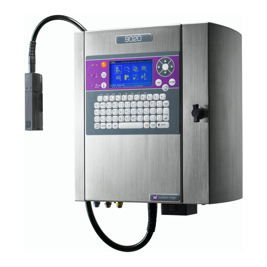
Printer description ■ Cabinet 9020 and 9030 are composed of a cabinet and a print head linked by a 3 metre umbilical. Front view Rear view (with printer holder) The cabinet must be hung vertically by the fixing points located on the rear side A minimum stand off of 90mm is necessary at the back of the printer to allow the door on the right side to be opened. - Page 27 Printer description The cabinet is very compact, the dimensions are: Height: 400 mm Width: 367 mm Depth: 239 mm Volume 35 dm (35 litres) Weight: is less than 20 kg (depending on options installed and cartridge status) A36163-B 27/182...
- Page 28 Printer description The electrical connections (power supply, industrial inputs/outputs, V24…), pneumatic connections (air pressurisation, vapours extraction…) and umbilical are located at the bottom of the cabinet. Important : The printer must run with the doors closed. A36163-B 28/182...
-
Page 29: Operator Interface
Printer description ■ Operator Interface The operator interface is user friendly thanks to • A screen with icons for daily operations & consumable level indication • Windows-type menu structure • Help message to guide the operator through the different menu levels •... - Page 30 Printer description Edition is made by morpheme (or phoneme), that is to say the smallest linguistic segment having an independent meaning, therefore being able to be represented by a Chinese character. Examples: beng, chan, li zao, etc. This acquisition is incremental. Examples: B results in 20 ideographs beginning with the sound [b], BE gives10 ideographs beginning with the sound [be],...
-
Page 31: Print-Head & Umbilical
Reminder: 9020 is only available in single jet, G type For 9030 IP65 printer, the print head is protected by a stainless steel head protection accessory (except on bent umbilical). Remark: This stainless steel head protection kit is available as an accessory for 9020. Characteristics: •... - Page 32 Printer description Nozzle cleaning During printer start-up & shutdown, make up solution is introduced into the modulation body to clean the cavity. During these 2 phases, the gutter electro valve is rinsed as well. Important : .The head level must be set correctly in the Preparation menu. The nozzle cleaning sequence is optimised according to the head level parameter.
- Page 33 Printer description On the cabinet side, the umbilical is available in 2 configurations: Normal configuration Angled umbilical output configuration Option: A35442 Head dimension A36163-B 33/182...
-
Page 34: Electronic Compartment
Printer description ■ Electronic compartment The electronic compartment is located on the left side of the printer. The main electronic elements are: • The mains filter (located in the bottom of the cabinet) • The power supply board (located at the top of the cabinet) •... - Page 35 Printer description CPU board 2 CPU boards are available. • One version for 9020 Single jet only and less input/output functionality for the industrial interface board. • One version for 9030 The same 9030 CPU board will drive single and twin jets, G or M 9030 printers.
-
Page 36: Hydraulic Compartment
Printer description ■ Hydraulic compartment The hydraulic compartment is on the right side of the printer. When the operator opens the door on the right, he only has access to the consumable cartridges and the PCMCIA slot. Make up cartridge Ink cartridge PCMCIA/Compact Flash card Ink Circuit: IC60... -
Page 37: Industrial Interface Connection Board
Printer description ■ Industrial Interface connection board The industrial interface connection board is located in the electronic compartment, accessible via the left door. There are 2 ways to connect an external device to the printer. For the basic and more common signals (photo cell, tacho & alarm), 3 IP65 external connectors are available to easy installation. - Page 38 Printer description Industrial Interface connection board The Industrial interface connection board allows the connection of external device. 2 types of boards are available. • Industrial interface connection board • Ethernet Industrial interface connection board (Industrial interface connection board + Ethernet connections) Industrial interface connection board A36163-B 38/182...
- Page 39 Printer description Inputs / Outputs 9020 9030 Object detection cell input 1 TOP1+ Standard (external Standard (external connector TOP1- connector) or Interface board) Object detector inhibition input INHTOP+ Option (Interface board) Standard (Interface board) INHTOP- Tacky coders input TACHY+ Standard...
- Page 40 Printer description Terminals +24VP ALDEF C ALDEF T ALDEF R OUT- OUT+ INCMES- INCMES+ COMPARA INVMES- INVMES+ ETATIMP+ SENSBIB- ETATIMP- SENSBIB+ SYNCMESS+ TACHY- SYNCMESS- TACHY+ +24VP +24VP TOP1+ A/M- TOP1- A/M+ TOP2+ IN1- TOP2- IN1+ RAZCPT1+ TXDI RAZCPT1- RXDI RAZCPT2+ TXDI+ RAZCPT2- RXD+I...
-
Page 41: General Specification
Printer description ■ General specification Physical characteristics Dimensions (mm) □ Printer body.......400 x 355 x 215 □ Print head (straight)....182 x 36 x 43 □ Consumable cartridge ....250 x 55 x 55 Weight (kg) □ Complete machine ....less than 20 kg □... - Page 42 Printer description Compliance with standard Safety □ Conformity (self-certification): CE marking conforms with the machine directive, the electromagnetic compatibility directive and the low voltage directive: CEI 60950 (UL 60950, EN60950), CEI 60204-1 (EN60204-1). □ Accreditations (third-party bodies): UL label according to UL 60950, CSA label according to CSA C.22.2.950, GS label according to EN 60204-1 and ZH 1/10* EX-RL/03.85.
-
Page 43: Energy
Printer description ■ Energy • 100 - 120V 0.5A alternative (Automatic switching). 200 - 240V 0.3A alternative (Automatic switching). Frequency 50 or 60 Hz Power 60 VA. Main fuse 1.25 AT • □ Air pressurised (for 9030 IP65) Specifications Value Air quality Max: 0.12 grams of water/m³... - Page 44 Printer description Notes: A36163-B 44/182...
-
Page 45: Installation
Installation A36163-B 45/182... - Page 46 Installation Notes: A36163-B 46/182...
-
Page 47: Oobcl
Installation ■ OOBCL Date: MARKEM-IMAJE Page: 1/1 C.S.Q.A. Out Of Box Checking List. OOBCL (to be filled by MARKEM-IMAJE technicians) Customer: Service engineer: File name: New printer or secondhand printer: Ink: QAG-127 A Serial Number: Type: Manufacturing date: Printer start up on: RECEPTION: SHIPMENT &... -
Page 48: Installation Of Two Cells
Installation ■ Installation of two cells NEW: Two object detection cells may be installed on 9020 and 9030 printers to measure the speed at which objects to be printed are conveyed and adjust the printing speed accordingly. IMPORTANT: the industrial interface board must be installed on the printer. - Page 49 Installation NOTE: This speed is an average. The calculation time is masked in the “margin” (Delay: R) The minimum margin is 3 mm. The margin is calculated based on the set speed programmed in the printer, not the calculated speed. The cell “pulses”...
-
Page 50: Starting The Printer For The First Time
Installation ■ Starting the printer for the first time □ Plug the AC power cord provided with the printer into an electrical outlet (do not modify it): Female plug into printer and rubber blanking cap Male plug into a standard outlet (2 pole, grounded) □... -
Page 51: Operator Information
Installation ■ Operator Information Daily start-up □ Press the On/Off button (press twice if screen is off). □ Press ENTER to confirm. The ink circuit and the jet start up automatically. The printer is ready to print when the green “Head Status” LED is lit steady. Starting time: approx. -
Page 52: Shutting Off The Printer For A Period Of Less Than Three Weeks
Installation Shutting off the printer for a period of less than three weeks □ Press On/Off. □ Press ENTER to confirm. The printer shuts off in approx. 30 seconds even if the jet is operating. Shutting off the printer for more than three weeks If the printer is to be shut off for a period of more than three weeks, it must be drained and rinsed (see Draining and Rinsing section). -
Page 53: Head Operations
Installation Head operations Starting and stopping the jet The jet only needs to be stopped when performing maintenance on the print head. Turn the jet back on after maintenance is completed. IMPORTANT: Turning off the jet does not turn off the machine. Cleaning the head □... - Page 54 Installation Unblock Nozzle Use this function (Production – Maintenance – Jet maintenance) when there is no jet or the jet is deflected. States of the head solenoid valves during this function Ink SV (A) Drain SV (B) Additive SV Rinsing SV Recovery SV Phase 1 Open...
- Page 55 Installation Intro. Cleaning Solution Use this function (Production – Maintenance – Jet maintenance) when the jet is deflected. States of the head solenoid valves during this function Ink SV (A) Drain SV (B) Additive SV Rinsing SV Recovery SV Phase 1 Closed Open Closed...
- Page 56 Installation Check Jet Stability Use this function (Production – Maintenance – Jet maintenance) when the jet is unstable. States of the head solenoid valves during this function Ink SV (A) Drain SV (B) Additive SV Rinsing SV Recovery SV Phase 1 Open Open Closed...
- Page 57 Installation General comments regarding head operations If a problem arises when the jet is turned on (unstable jet or no jet), all four operations (Unblock Nozzle, Intro. Cleaning Solution, Check Jet Stability and Head Cleaning) may be need to be performed to correct it. If the problem persists despite repeating the sequence three times in a row, turn off the printer before removing or changing its parts.
- Page 58 Installation Notes: A36163-B 58/182...
-
Page 59: After Sales Service Policy
After sales service policy A36163-B 59/182... - Page 60 After sales service policy Notes: A36163-B 60/182...
-
Page 61: Access Maintenance Agreement
After Sales Service Policy ■ ACCESS maintenance agreement Purpose: List of points to be checked during ACCESS maintenance agreement 9020 / 9030 1 - General information Customer name: ___________________________ Date : ___________________________ Town : ___________________________ Printer serial no. : ___________________________ Contact name : ___________________________ Visit report no. - Page 62 After Sales Service Policy 4 – Operational check before maintenance Not OK Comments Operator interface functioning ____________________________________ Printer start-up ____________________________________ Jet centered and stable ____________________________________ No gutter overflow ____________________________________ Break-off point setting ____________________________________ Jet speed differential jet1 to jet 2 < 1m/s ____________________________________ Pref: ______b Pacc: ______b T: ______°C...
- Page 63 After Sales Service Policy 5 – Parts replaced Pressurization kit filter Part Location Part number: ENM16203 Location: left side of the printer Part cabinet replaced Replacement: 6 months * * depends on the quality of the air and can be adjusted accordingly Quantity: 1 Air filters ** Part...
- Page 64 After Sales Service Policy 6 – Printer rinsing The printer must be rinsed every two years Last printer rinsing date: ___ / ___ / ___ Rinsing: required Rinsing: complete Not OK Comments: ______________________________________________________________ 7 – Parts replaced (other than those included in the maintenance agreement) Parts replacement Part number Description...
- Page 65 After Sales Service Policy 10 User Comments The user knows the safety rules ____________________________________ Printer documentation is available ____________________________________ The user knows basic maintenance ____________________________________ procedures The user knows how to use the operator ____________________________________ interface The user needs training ____________________________________ 11 Maintenance report Comments...
- Page 66 After Sales Service Policy Appendix: Time schedule We have tried to estimate the time you need for each section. This sheet is for the Markem-Imaje network, but can be given to the customer on request. § Section Approx Comments time (min) General information To be filled in before service Printer information before maintenance...
-
Page 67: Standard Maintenance Agreement
After Sales Service Policy ■ STANDARD maintenance agreement Purpose : List of points to be checked during STANDARD maintenance agreement 9020 / 9030 1 - General information Customer name: ___________________________ Date : ___________________________ Town : ___________________________ Printer serial no. : ___________________________ Contact name : ___________________________ Visit report no. - Page 68 After Sales Service Policy 4 – Operational checks before maintenance Not OK Comments Operator interface functioning ____________________________________ Printer start-up ____________________________________ Jet centered and stable ____________________________________ No gutter overflow ____________________________________ Break-off point setting ____________________________________ Jet speed differential jet1 to jet 2 < 1m/s ____________________________________ Pref: ______b Pacc: ______b T: ______°C...
- Page 69 After Sales Service Policy 5 – Parts replaced Pressurization kit filter Part Location Part number: ENM16203 Location: left side of the printer Part cabinet replaced Replacement: 6 months * * depends on the quality of the air and can be adjusted accordingly Quantity: 1 Air filters ** Part...
- Page 70 After Sales Service Policy Ink circuit** Part Location Part number: related to the ink base Part replaced Location: accessible from the right door Replacement: 8 000 Hrs (active hours counter) or 4 years Quantity: 1 **: the printer must be rinsed before changing the ink circuit 6 –...
- Page 71 After Sales Service Policy 9 –Operational test after parts replacement and update Not OK Comments Printer start-up ____________________________________ No ink leakage ____________________________________ Ink type setting ____________________________________ Head level setting ____________________________________ Autocalibration ____________________________________ (only if the ink circuit has been changed) Not OK Comments Fault checking...
- Page 72 After Sales Service Policy 11 Maintenance report Comments Maintenance complete ____________________________________ ____________________________________ ____________________________________ ____________________________________ ____________________________________ Action to be taken by Markem-Imaje by ___ / ___ / ___¤ Action to be taken by customer by ___ / ___ / ___ ¤ ¤...
- Page 73 After Sales Service Policy Appendix: Time schedule We have tried to estimate the time you need for each section. This sheet is for the Imaje network, but can be given to the customer on request. § Section Approx Comments time (min) General information To be filled in before service Printer information before maintenance...
- Page 74 After Sales Service Policy Notes: A36163-B 74/182...
-
Page 75: Maintenance
Maintenance A36163-B 75/182... - Page 76 Maintenance Notes: A36163-B 76/182...
-
Page 77: Preventive And Proactive Maintenance Table
Maintenance ■ Preventive and proactive maintenance table Frequency Action Duration Comments When clogging Clean the print head 5 min. See “User manual”. causes the printer to malfunction or to produce poor quality print. 4000 hours* Change the filter of the 10 min. -
Page 78: Three Reasons Why 9020/30 Printers Require Maintenance
Maintenance ■ Three reasons why 9020/30 printers require maintenance Ink circuit Mechanical components in the hydraulic system wear down due to repetitive movements (solenoid valves, pumps), rubbing, chemical attack (seals) and temperature variations. Narrow passages (nozzle, leaks or calibrated passages) can become partially clogged with ink particles or dust entering the ink circuit. -
Page 79: To Sum Up
Maintenance ■ To sum up Ink Circuit Moving parts - Presence of wear parts Solenoid valves Seals Pumps Active chemical - Micro-conduit - Limited life Restrictors - Fast drying Nozzle - Sensitive to temperature - Filters variations Main filter Grids Ink/printer Ink preparation - Pressure... - Page 80 Maintenance Notes: A36163-B 80/182...
-
Page 81: Troubleshooting
Troubleshooting A36163-B 81/182... - Page 82 Troubleshooting Notes: A36163-B 82/182...
-
Page 83: Abbreviations Table Used In This Chapter
Troubleshooting ■ Abbreviations table used in this chapter Abbreviation Signification Accu Accumulator Algo Algorithm Ink Circuit Central Process Unit Cyclic Redundancy Control Print Module Piezo Piezoelectrique Resonator After Sales Services A36163-B 83/182... -
Page 84: Troubleshooting
Troubleshooting ■ Troubleshooting. The first thing to do is to read the help message displayed on the printer. The table on the following pages provides details regarding the alarm or fault displayed. The first column gives the number (in ascending order) and type of alarm or fault: A: alarm, printing may continue D: fault, printing disabled The third column lists checks, causes, remedies and solutions by order of probability. - Page 85 Troubleshooting A / D Description Context Check / Cause / Remedy / Solution Consequences CRC EEPROM The CRC calculated when the printer is switched on is Ink circuit different from the CRC incorrect stored. Consequences: The IC60 time counter information is lost, but the module continues to run as usual.
- Page 86 Troubleshooting A / D Description Context Check / Cause / Remedy / Solution Consequences Internal The dialogue between the Restart the printer CPU processor and the communication Printing processor was timeout interrupted at start-up. Consequences: Printing is disabled. Incorrect The data received from the Check the value of the check byte and whether the external connection is wrong.
- Page 87 Troubleshooting A / D Description Context Check / Cause / Remedy / Solution Consequences Duplicate print Three conditions are required Check timing of sending of messages and Dtop. for this fault to appear: not authorized the serial link is used. the “Print-out no double up”...
- Page 88 Troubleshooting A / D Description Context Check / Cause / Remedy / Solution Consequences CRC(RAM) Ink Appears after the CPU is Check the position of the battery jumper on the Incorrect reset. CPU. Check the voltage of the CPU battery. Consequences: Replace the CPU Stored data (IC60 time...
- Page 89 Troubleshooting A / D Description Context Check / Cause / Remedy / Solution Consequences Read/write error impossible to read or write to IC60 on Ink Cir the IC60 EEPROM during EEPROM operation. Consequences: The IC60 counter values are no longer saved.
- Page 90 Troubleshooting A / D Description Context Check / Cause / Remedy / Solution Consequences Algorithm not The message selected or Check the algorithms available and load the missing available sent over the serial link ones in the *.HEM file. contains an algorithm number not available in the printer.
- Page 91 Troubleshooting A / D Description Context Check / Cause / Remedy / Solution Consequences EMPTY MAKE UP After several attempts to Cartridge Cartridge pump make up from the Not empty cartridge, the printer Correctly positioned in cartridge holder indicates that the cartridge is Properly perforated empty.
- Page 92 Troubleshooting A / D Description Context Check / Cause / Remedy / Solution Consequences U1: Make up The negative pressure Cartridge Valve malfunction measured while make up is - Empty being pumped from the - Hollow needle blocked by unperforated cartridge is too high cartridge Consequences:...
- Page 93 Troubleshooting A / D Description Context Check / Cause / Remedy / Solution Consequences Ink concentration During printing the working Check the following parameters: out of pressure required for proper specifications jet speed is outside the P = Head height difference f(T) curve.
- Page 94 Troubleshooting A / D Description Context Check / Cause / Remedy / Solution Consequences Ink transfer The time needed at start-up Condenser vent. timeout and during operation for the Clean condenser to drain to the accumulator via SVs 4 and 3, Test solenoid valves 2, 3 and 4.
- Page 95 Troubleshooting A / D Description Context Check / Cause / Remedy / Solution Consequences Pump The ink pump compression Test solenoid valves 0, 1, 2, 3 and 4 performance ratio is insufficient. incorrect IC60 Consequences: No direct consequences. The printer remains ready.
- Page 96 Troubleshooting A / D Description Context Check / Cause / Remedy / Solution Consequences Ink concentration The pressure during Check the faults 53 and 70 out of range operation is far outside of in this table tolerance from the curve P = f(T) Rinse the printer.
- Page 97 Troubleshooting A / D Description Context Check / Cause / Remedy / Solution Consequences High Voltage The printer detected an Cleanliness of deflection plates insulation failure insulation fault on the EHT Cleaning with soapy water and letting dry may solve lines during operation the problem.
- Page 98 Troubleshooting A / D Description Context Check / Cause / Remedy / Solution Consequences Pressure servo If the air pocket is too small Test solenoid valves 3 and 4 control during operation, the pressure inside is disrupted IC60 when ink is added, making jet speed control impossible.
-
Page 99: Maintenance Procedures
Troubleshooting ■ Maintenance procedures Solenoid valve test. The “Test solenoid valves” function makes it possible not only to know (by listening) whether a solenoid valve responds to a command signal, but also to release a stuck solenoid valve by actuating it several times. WARNING: Ink or make up may splash out during the procedure. -
Page 100: Releasing Solenoid Valve 0
Troubleshooting Releasing solenoid valve 0 WARNING: Ink or make up may splash out during the procedure. Take precautions, and wear gloves and safety glasses. COMMENT: It is not necessary to remove the IC60 from the console to release solenoid valve 0. Turn the printer On and select “Test ink solenoid valve U0”. -
Page 101: Partial Drain
Troubleshooting Partial drain This will empty the ink in the buffer tank without rinsing it. A depressurized empty cartridge is necessary. Follow the instructions that appear on the screen. WARNING: Follow the instructions carefully to avoid spilling any fluid. Wear gloves and safety glasses. -
Page 102: Auto-Calibration
Troubleshooting Auto-calibration. ■ When to perform auto-calibration □ After replacing the Print Module □ After replacing the CPU □ After replacing the IC60 ■ Why perform auto-calibration The jet speed control ensures print quality over time. The control depends on the ink type and several printer components (such as the printing module and the ink circuit IC60 IC60). - Page 103 Troubleshooting NOTE: If the head is not at the auto-calibration position when the head is placed in the working position, the head height difference must be changed and adjusted. Do not let the head and jet operate for too long on its maintenance stand if the stand is not at the working position.
-
Page 104: List Of Special Spare Parts For Markem-Imaje Technicians
Piezo board (twin jet) See corresponding SPS ENM36675 CPU board 9020 RoHS ENR36675 CPU board 9020 RoHS ENR34024 CPU board 9020 Non RoHS See corresponding SPS ENM36676 CPU board 9030 RoHS ENR36676 CPU board 9030 RoHS ENM27781 CPU board 9030 Non RoHS... -
Page 105: In This Chapter
Troubleshooting ■ List of the spare parts for customers with spare parts sheets available in this chapter. Description Comments Industrial Interface Board 2 available types. See ref in the spare parts catalog. See SPS for replacing. Keyboard Several available types. See ref in the spare parts catalog. -
Page 106: Spare Parts Sheets
Troubleshooting ■ Spare parts sheets INTRODUCTORY NOTE: The Spare Parts Sheets (SPS) in this section were written with preventive maintenance in mind. During curative maintenance it is not always possible to follow the recommended procedures in full (e.g. it might not be possible to drain the ink circuit IC60 if a solenoid valve is stuck). -
Page 107: Replacing A Modulation Assembly
Troubleshooting Replacing a modulation assembly Tools: 1.5 mm Allen key CAUTION: Turn off the printer and unplug it from its AC outlet. Residual ink may pour out, take appropriate precautions. Perform this operation in a dust-free environment. Disassembly: □ Open the head cover. Remove the resonator protective cover. Disconnect the resonator wires. -
Page 108: Replacing A Resonator
Troubleshooting Replacing a resonator Tools: 1.5 mm Allen key; resonator clamping/loosening rod. CAUTION: Turn off the printer and unplug it from its AC outlet. Residual ink may pour out, take appropriate precautions. Perform this operation in a dust-free environment. Disassembly: □... -
Page 109: Replacing The 4 Solenoid Valve Block
Troubleshooting Replacing the 4 solenoid valve block Tools: 1.5 mm Allen key. CAUTION: Turn off the printer and unplug it from its AC outlet. Position the head higher than the printer console. Residual ink may pour out, take appropriate precautions. Perform this operation in a dust-free environment. -
Page 110: Replacing The Recovery Unit
Troubleshooting Replacing the recovery unit Tools: 2.5 mm flat-bladed screwdriver CAUTION: Turn off the printer and unplug it from its AC outlet. Residual ink may pour out, take appropriate precautions. Disassembly: □ Remove the four screws at the corners of the recovery assembly and remove it. Pay attention to the seals (O-rings around pins). -
Page 111: Replacing A Gutter
Troubleshooting Replacing a gutter Tools: 0.9 mm Allen key, Markem-Imaje gutter adjustment tool. CAUTION: The jet must be stopped. Residual ink may pour out, take appropriate precautions. Disassembly: □ Loosen the grub screw on the same side as the gutter to be replaced, by half a turn. □... -
Page 112: Replacing The Recovery Solenoid Valve
Troubleshooting Replacing the recovery solenoid valve Tools: 1.5 mm Allen key; 2.5 mm flat-bladed screwdriver; 7 mm box wrench CAUTION: Turn off the printer and unplug it from its AC outlet. Position the head higher than the printer console Residual ink may pour out, take appropriate precautions. Disassembly: □... - Page 113 Troubleshooting Reassembly: □ Solder the control wires to the new solenoid valve. □ Connect the intake hose and slide the sleeve back. □ Fit new seals (two O-rings) to the new solenoid valve. □ Position the solenoid valve in its housing (check that it is oriented correctly) then retighten the nut.
-
Page 114: Replacing The Print Module
Troubleshooting Replacing the print module Tools: 2 mm, 2.5 mm and 4mm Allen keys. CAUTION: Rinse and drain the printer then turn it off and unplug it from its AC outlet. Residual ink may pour out, take appropriate precautions. Disassembly: □... - Page 115 Troubleshooting Reassembly: □ Fit a new O-ring on the attachment plate then reassemble and connect the umbilic (electrical and hydraulic connectors and ground wire). □ Position the stainless steel plate. CAUTION: the hoses must not obstruct the fan. □ Reassemble the cartridge support plate. Testing: □...
-
Page 116: Replacing The Ink Circuit Ic60
Troubleshooting Replacing the ink circuit IC60 Tools: 2.5 mm, 4mm and 5 mm Allen keys. CAUTION: Rinse and drain the printer then turn it off and unplug it from its AC outlet. If you are unable to use the automatic "Drain/rinse" function due to problems on the ink circuit IC60 you may use the procedure below to drain the ink circuit IC60 manually. - Page 117 Troubleshooting CAUTION: If the "drain/rinse" function has not been performed, the accumulator may contain ink under pressure. Take particular precautions when draining it. Connect the printer to the electrical supply, hold the hydraulic half-connector on the ink circuit IC60 side in an appropriate receptacle (500 cm , half-closed) and manually open solenoid valve "U11, Accu.
- Page 118 Troubleshooting Reassembly: □ Fit the two screws to the new ink circuit IC60. □ Hang it at the place of the cartridge support plate in order to connect the venting hose and the CPU ribbon cable. □ Bring up the new ink circuit IC60 at its definitive place. Insert the two screws into the corresponding slots and the two bottom mounts in their brackets.
-
Page 119: Replacing The Eht Block
Troubleshooting Replacing the EHT block Tools: 2 mm, 2.5 mm and 4mm Allen keys. CAUTION: Turn off the printer and unplug it from its AC outlet. Disassembly: □ Open the left door. □ Disconnect the two connectors from the EHT wires and the EHT control connector. □... -
Page 120: Replacing The Industrial Interface Card
Troubleshooting Replacing the industrial interface card Tools: 2.5 mm and 4mm Allen keys ; 2.5 mm flat-bladed screwdriver. CAUTION: Unplug the printer from its AC outlet. Disassembly: □ Open the left door. □ Disconnect all the wires connected to the industrial interface board terminal blocks (cell, tachometer, etc.). -
Page 121: Replacing The Cpu Board
Troubleshooting Replacing the CPU board Tools: 2.5 mm and 4mm Allen keys. CAUTION: If possible, save the messages to a PCMCIA/Compact Flash card. Unplug the printer from its AC outlet. Disassembly: □ Open the printer's left side door. Remove the two screws then disconnect the industrial interface board from the CPU board without removing the wires connected to □... - Page 122 Troubleshooting Reassembly: □ Before inserting the new board, check that jumper S32 is in the ON position. □ Connect the display to the new CPU board (see the "Replacing the display" sheet). □ Insert the three screws on the right side of the board but do not tighten them. □...
-
Page 123: Replacing The Display
Troubleshooting Replacing the display Tools: 2 mm and 4mm Allen keys. CAUTION: Unplug the printer from its AC outlet. Disassembly: □ Remove the CPU board (see the "Replacing the CPU board" sheet). There is no need to store the messages. □... -
Page 124: Replacing The Psu Board
Troubleshooting Replacing the PSU board Tools: 2.5 mm and 4mm Allen keys. CAUTION: Unplug the printer from its AC outlet. Do not lay the printer down. Disassembly: □ Open the left side door. □ From the outside of the printer, unscrew the three screws that hold the power supply board to the radiator. -
Page 125: Replacing The Adp Board
Troubleshooting Replacing the ADP board Tools: 1.5 mm Allen key; 2.5 mm flat-bladed screwdriver; tweezers. CAUTION: Turn off the printer and unplug it from its AC outlet. Disassembly: □ Remove the rear head cover □ Unscrew the two screws from the ADP board and withdraw it from its housing. □... -
Page 126: Replacing The Piezo Board
Troubleshooting Replacing the piezo board Tools: 1.5 mm Allen key ; 2.5 mm flat-bladed screwdriver ; 4 mm and 7 mm box wrench ; tweezers. CAUTION: Turn off the printer and unplug it from its AC outlet. The head must be rinsed (partial drain of the printer). Place the head higher than the ink circuit IC60. - Page 127 Troubleshooting OPTIONAL BUT RECOMMENDED FOR BETTER ACCESS TO THE PIEZO BOARD: Unscrew the screw holding the two ground braids attached to the body of the recovery solenoid valve. Remove the recovery assembly. To avoid damaging the assembly, loosen the four screws in the corners of the assembly one full turn (do not loosen the central screw), detach the recovery assembly (little notch, on the right side), remove the four screws and gently remove the recovery...
- Page 128 Troubleshooting Reassembly: CAUTION: Before reassembly, check that all items are clean and wipe off any traces of ink or make up. □ Solder the wires onto the new board and plug the connector back in. □ Put the board back in place, taking care to engage the control screws correctly in the corresponding potentiometers.
-
Page 129: Air Intake Filter Cartridge And Seal (On Air Pressurisation Kit)
Troubleshooting Air intake filter cartridge and seal (on air pressurisation kit). Tools: 4mm Allen key; 2.5 mm flat-bladed screwdriver. CAUTION: The printer must be disconnected from the power supply and the compressed air network. Disassembly: □ Open the left door. □... -
Page 130: Replacing The Keyboard
Troubleshooting Replacing the keyboard Tools: 4mm Allen key. Bottle of make-up, alcohol or acetone. Absorbent paper. CAUTION: Unplug the printer from its AC outlet. Disassembly: □ Open the left door and disconnect the keyboard ribbon cable from the CPU board. □... -
Page 131: Adjustment Sheets
Troubleshooting ■ Adjustment sheets Break-off point adjustment Tools: Magnifying glass (eyepiece) ; 2,5 mm Allen key. Preparation: □ Place the head on its maintenance stand. □ Turn on the jet(s) for at least 30 minutes. □ Remove the head cover. Adjustment: To adjust the break-off point, look at the jet in front of the charge electrode (stroboscopic LED) through the eyepiece (see Figure 1) - Page 132 Troubleshooting □ Figure 2 shows how a properly adjusted break-off point should appear. Look only at the shape of the drops just under the break-off point. Wrong To avoid Right Figure 2 Adjust the potentiometer with care to avoid damaging it. Checks and tests: □...
-
Page 133: Recovery Gutter Adjustment
Troubleshooting Recovery gutter adjustment Tools: □ Safety glasses and gloves; 0.9 mm Allen key; gutter adjustment tool. Preparation: □ Place the head on its maintenance stand. □ Confirm the Production / Maint / Jet maintenance / Adjust jet function. □ Remove the head cover. Adjustment: □... - Page 134 Troubleshooting Notes: A36163-B 134/182...
-
Page 135: Hydraulics
Hydraulics A36163-B 135/182... - Page 136 Hydraulics Notes: A36163-B 136/182...
-
Page 137: Solenoid Valve Hydraulic Circuit (Printer Stopped )
Hydraulics ■ Solenoid valve hydraulic circuit (Printer stopped) This circuit is equipped with solenoid valves on the air pump (U 5 and U 6 ). This ink circuit can be installed in a IP54 console (figure 1) or in a IP65 console (figure 2). Motor Accumulator Condensor... -
Page 138: Non Return Valve Hydraulic Circuit (Printer Stopped )
Hydraulics ■ Non return valve hydraulic circuit (Printer stopped) This circuit is equipped with non return valves on the air pump (U 5 and U 6 ). This ink circuit can be installed in a IP54 console (figure 1) or in a IP65 console (figure 2). Motor Accumulator Condensor... -
Page 139: Diagram Of The Hydraulic Circuit (Normal Operation)
Hydraulics ■ Diagram of the hydraulic circuit (Normal operation) Motor Accumulator Condensor Buffer 310cm 180cm 460cm Make Up RE 6 AS 5 PR 11 Pompe air TA 2 ELV 10 CO 4 SO 1 Pompe encre AC 3 EN 0 Head pressu kit (option) Exit of the... -
Page 140: Diagram Of The Hydraulic Circuit (Jet Stopped With Make Up )
Hydraulics ■ Diagram of the hydraulic circuit (Jet stopped with make up) Motor Accumulator Condensor Buffer 310cm 180cm 460cm Make Up RE 6 AS 5 PR 11 Air pump TA 2 ELV 10 CO 4 SO 1 Ink pump AC 3 EN 0 Head pressu kit (option) -
Page 141: Ink Circuit: Principle Of Operation
Hydraulics ■ Ink circuit: principle of operation The core of this ink circuit comprises of two separate diaphragm pumps operated by a single motor. Nine solenoid valves located around these pumps (controlled by software) transfer fluids between the various tanks. The "air pump"... -
Page 142: Print Head
Hydraulics ■ Print head The print head on the Markem-Imaje 9020 and Markem-Imaje 9030 has five solenoid valves. Four of them are grouped in a "solenoid valve block" (solenoid valves A, B, C and D) and the fifth stands alone (solenoid valve E). -
Page 143: Diagram Of Recovery Gutter Solenoid Valve
Hydraulics ■ Diagram of recovery gutter solenoid valve E. Travel Make up Exhaust Gutter Piston Return spring Electrical lugs ■ Recovery gutter The gutter is open when solenoid valve E is activated (powered) and closed when it is idle (unpowered). During maintenance procedures the software automatically changes the gutter status (open or closed) depending on the command. - Page 144 Hydraulics Notes: A36163-B 144/182...
-
Page 145: Principle Of Transfers
Hydraulics ■ Principle of transfers Each transfer can be broken down schematically into six phases: Phase 1: With the motor stopped, one solenoid valve on each pump is opened. Phase 2: The motor rotates by half a turn, raising the double piston and generating suction (intake) through the open solenoid valves, then stops. - Page 146 Hydraulics Delivery Suction Suction Delivery Pressure in the pump ELV0 Opened Closed Ink transfer: Cartridge Accu. ELV3 Opened Closed ELV5 Opened Closed Air transfer: Buffer Condensor ELV 6 Opened Closed A36163-B 146/182...
-
Page 147: Ink Filters
Hydraulics ■ Ink filters The primary filter is inside the accumulator on the ink circuit. It cannot be changed. To reach the 14 µ grid filter on the SV 11 inlet, remove the solenoid valve's support bell. Removing the filter is not recommended (risk of ink circuit contamination). ■... -
Page 148: Constant Ink Concentration Principle
Hydraulics ■ Constant ink concentration principle The printer uses the "constant concentration" principle. The ink temperature is measured continuously in the print head, using a temperature sensor on the ADP board. The jet speed is also measured continuously. Depending on the temperature measured, the ink type, and head type, a theoretical pressure is defined to obtain the correct jet speed. -
Page 149: Jet Speed Calculation And Adjustment
Hydraulics ■ Jet speed calculation and adjustment For high quality printing, the jet must be at a constant speed. The software continuously measures the speed and adjusts it if necessary. Jet speed calculation Speed = Distance / Time The principle used to measure the speed is as follows: A sequence of seven consecutive drops is charged with a specific, precise amount of charge when it passes through the charge electrode. -
Page 150: Negative Pressure Measuring And Adjustment
Hydraulics ■ Negative pressure measuring and adjustment Measuring of the negative pressure The negative pressure is measured with the pressure sensor underneath the ink pump, when transferring ink into the buffer tank. This measured value is compared to a set point value. -
Page 151: Gutter Solenoid Valve Rinsing
Hydraulics ■ Gutter solenoid valve rinsing At the end of the “Stop printer” procedure the gutter solenoid valve is rinsed. Solenoid valve D delivers make up to clean the seat, core and spring in solenoid valve E. During this phase the solenoid valve is opened and closed in order to properly clean it and the pipe leading back to the buffer tank. - Page 152 Hydraulics Motor Accumulator Condensor Buffer 310cm 180cm 460cm Make up RE 6 AS 5 PR 11 Pompe air TA 2 ELV 10 CO 4 SO 1 Pompe encre AC 3 EN 0 Head pressu Exit condensor A36163-B 152/182...
- Page 153 Hydraulics Notes: A36163-B 153/182...
- Page 154 Hydraulics Notes: A36163-B 154/182...
-
Page 155: Electronics
Electronics A36163-B 155/182... - Page 156 Electronics Notes: A36163-B 156/182...
-
Page 157: 9020/9030 Electronic Architecture
Electronics ■ 9020/9030 Electronic Architecture External Industrial External Graphical user Back light RS232 Interface Terminal Interface Battery Reset Save Temperature FPGA Hemis Print I C +GUI I / O 68331 68331 Horodator Shared RAM 1M Sram 2M 1M Sram Pressure... -
Page 158: Cpu Connections
Electronics ■ CPU Connections A36163-B 158/182... -
Page 159: Connectors On Cpu Board
Electronics ■ Connectors on CPU board J3 Motor J19 Ventilator J1 Power supply S32 Battery ] ON J4 Command EHT J13 Not used CAUTION: After use the RESET button, adjust RESET button the contrast of the screen (Keys ALT and J11 BD32 Print J7 Keyboard/LED J5 Head... -
Page 160: Connectors On Industrial Interface Board
Electronics ■ Connectors on industrial interface board +24VP ALDEF C ALDEF T ALDEF R OUT- OUT+ INCMES- INCMES+ COMPARA INVMES- INVMES+ ETATIMP+ SENSBIB- ETATIMP- SENSBIB+ SYNCMESS+ TACHY- SYNCMESS- TACHY+ +24VP +24VP TOP1+ A/M- TOP1- A/M+ TOP2+ IN1- TOP2- IN1+ RAZCPT1+ TXDI RAZCPT1- RXDI... -
Page 161: External Connectors
Electronics ■ External connectors Tacky Photo cell 1 Alarm Tacky connector (blue mark) Blue (0V) Black (Tacky +) Tachy - White (Tacky -) +24V Brown (+24V) Tachy + Cell 1 connector (black mark) Blue (0V) Black (Top +) Top - White (Top -) +24V Brown (+24V) - Page 162 Electronics Notes: A36163-B 162/182...
-
Page 163: General Information
General information A36163-B 163/182... - Page 164 General information Notes: A36163-B 164/182...
-
Page 165: Ink Jet Printing
■ Ink jet printing Ink jet printing is a non-contact method of marking a product to identify, date or customize Markem-Imaje 9020 and 9030 printers use the continuous ink jet principle, writing in a conventional matrix layout. ■ Matrix printing Each symbol is defined in a rectangular area, divided into columns known as rasters. -
Page 166: Deviated Continuous Ink Jet
General information ■ Deviated continuous ink jet The print head is supplied with ink under pressure. This ink is ejected from the modulation assembly (1) via the nozzle (2), in the form of a jet (3). The jet is stimulated by a piezo-electric resonator in order to create consistent drops of ink. -
Page 167: Resonator Block
General information Resonator block The modulation assembly is a low-volume cavity in which pressurized ink is conditioned (regular jet flow, no air bubbles, modulation) before passing through the ejection nozzle to form a controlled jet. Piezo-electric resonator The piezo-electric resonator comprises a quartz crystal glued to a metal bar. When an alternating electrical signal is applied to the resonator, it vibrates in phase with the signal. -
Page 168: Algorithms
(the speed at which the object moves relative to the head). Using algorithm on 9020 and 9030 printers An algo is defined by several parameters:... -
Page 169: Calculation Of The Maximum Speed Of An Algo
General information Calculation of the maximum speed of an algo: Maxi speed = 1 / (Fpiezo * nb of drop in the raster * resolution ) - fpiezo = 16µs for a G head and 12µs for a M head) - resolution nb of drops / mm Example: Algo 004G10_07_01_28_18 1 / (0,000016 * 18 * 2,8) = 1240 mm/s... -
Page 170: Algorithm Table
General information Algorithm table (speed calculations +0, -5mm) HEAD G Number Name Resolution Speed max Head/objet distance mm/mn 001G10_05_01_28_05 2,8 pts/mm 4460 10mm 002G10_07_01_28_07 2,8 pts/mm 3185 10mm 003G10_16_01_28_17 2,8 pts/mm 1310 10mm 004G10_07_01_28_18 2,8 pts/mm 1240 10mm 005G10_16_01_28_40 2,8 pts/mm 0555 10mm 011G10_11_01_28_12... -
Page 171: Algos Curvprint
General information HEAD M Number Name Resolution Speed max Head/objet distance mm/mn 006M08_05_01_45_06 4,5 pts/mm 3085 08 mm 007M08_07_01_45_08 4,5 pts/mm 2310 08 mm 008M08_07_01_45_26 4,5 pts/mm 0710 08 mm 009M08_16_01_45_53 4,5 pts/mm 0345 08 mm 010M08_16_01_45_19 4,5 pts/mm 0970 08 mm 015M08_11_01_45_16 4,5 pts/mm... -
Page 172: Printing, Pressure, Speed
- quality at constant concentration (S7, 9020, 9030) Ink under pressure Examples: - In the Markem-Imaje 9020/9030 or the S8 Contrast, the accumulator is a pressurized reservoir of ink. - In the S8 Master or Classic, pressure is generated on demand by the pump. -
Page 173: Atmospheric Pressure, Absolute Pressure, Relative Pressure
General information ■ Atmospheric pressure, absolute pressure, relative pressure Atmospheric pressure Atmospheric pressure is around 1013 mbar at sea level. This pressure, given by weather services, corresponds to the "weight" of the atmosphere on a unit surface area. The value depends primarily on altitude. Absolute pressure An absolute pressure of 0 bar would be obtained in a perfect vacuum. -
Page 174: Pressure In A Liquid
General information Pressure in a liquid P atmos. P = ρgh where P = pressure at a point in the liquid, ρ = density of the liquid, g = normal acceleration due to gravity, h = height between the surface of the liquid and the point considered. -
Page 175: Relationship Between Ejection Speed And Pressure
General information Relationship between ejection speed and pressure The vessel is pierced with a small hole below the level of the liquid (h is negative) Consider point A to be at the surface of the liquid (level 0), and point B to be at the hole. Level 0 The liquid escapes through the hole at speed V. -
Page 176: Calculating The Ejection Speed
General information Calculating the ejection speed + ρV /2 + ρgh + ρV /2 + ρgh = Atmospheric pressure = 0 (no movement at point A) = 0 (origin for levels) = Atmospheric pressure The equation becomes: ρV /2 + ρgh = 0 (with h negative) = √2gh... -
Page 177: Fundamental Units
General information ■ Fundamental units Mass 1 kilogram (kg) = 2.2046 pound (lb) 1 lb = 0.4536 kg Length 1 meter (m) = 3.281 feet (ft) 1 inch = 25.4 mm 1 yard = 0.9144 m Volume 1 liter (l) = 0.2642 US gallons 1 US gallon = 3.785 l 1 cubic meter (m ) = 35.315 cubic feet... -
Page 178: Exercise
General information ■ Exercise: Level 0 water Neglect the effects of the fluid's viscosity. Calculate the ejection speed of the jet at the hole for the following values: P = 2.0 bar h = 0 m P = 2.0 bar h = - 2 m P = 2.0 bar h = + 2 m... - Page 179 General information Notes: A36163-B 179/182...
- Page 180 General information Notes: A36163-B 180/182...
- Page 182 Head Office 9, rue Gaspard Monge BP 110 26501 Bourg-lès-Valence Cedex France A36163-B Tel : (33) 4 75 75 55 00 Fax : (33) 4 75 82 98 10 http://www.imaje.com July 20008...
Need help?
Do you have a question about the 9020 and is the answer not in the manual?
Questions and answers
How To Solve 9020 High Voltage Insulation failure Problem.
To solve the high voltage insulation failure problem for the Markem-Imaje 9020, follow these steps:
1. Clean the Deflection Plates – Use soapy water to clean the deflection plates and let them dry completely.
2. Check Inside the Print Head – Open the rear cover and clean any ink or moisture buildup.
3. Dry the Area – Ensure all cleaned components are fully dry before reassembling.
4. Inspect for Leaks – Identify and eliminate any sources of current leaks.
5. Check the EHT Block and Print Module – If the issue persists, inspect these components for faults.
These steps should help resolve the insulation failure and restore proper operation.
This answer is automatically generated
@Mr. Anderson Thanks for your Help
U5. Ve U6 valfler çalışmıyor. Valf test yaptım 30 dakika denedim.
Hi, I have a MARKEM IMAJE 9020 PRINTER and I'd like to put the Registered trademark symbol in, how can I do that?
how i change the date and hours , Sommer houer
81 Default. Drop detection jet 1 (left) Clean and dry carefully head and cover... Done this numerous times but error returns
To resolve the "81 Default. Drop detection jet 1 (left)" error on a Markem Imaje 9020 after cleaning the head and cover, follow these steps:
1. Check Ink Quality – Ensure that the ink is of the correct viscosity. If it is too thin or too thick, it may affect drop detection.
2. Inspect Print Module Connections – Look for any cut wires in the umbilical that may be causing a connection issue.
3. Verify Jet Detection – Ensure the recovery detector is correctly identifying the jet in the gutter. Clean the nozzle and modulation assembly if necessary.
4. Check Gutter Blockage – Make sure the gutter is not obstructed, and the negative pressure is within the correct range.
5. Adjust Break-Off Point – Use a magnifier to check the drop formation under the break-off point and adjust the potentiometer carefully if needed.
6. Perform Auto-Calibration – Run the auto-calibration function to fine-tune jet stability.
7. Close the Head Cover – Ensure the head cover is properly closed, as safety mechanisms may prevent operation if it's open.
After completing these steps, perform a test print to confirm the issue is resolved.
This answer is automatically generated