Table of Contents
Advertisement
Quick Links
Advertisement
Table of Contents
Troubleshooting

Related Manuals for Dover markem-imaje 9750


Summary of Contents for Dover markem-imaje 9750
-
Page 1: User Manual
User Manual 9750 for parts & service call QLC (800) 837-1309... - Page 2 for parts & service call QLC (800) 837-1309...
-
Page 3: Table Of Contents
User manual | | 9750 Summary User Manual General Description Printer The printing module Head pressurisation kit (optional) Standalone compressor kit (optional) Interface Preview of the main screen Interface usage principles Consult operating information of the interface Viewing a job Starting up the printer Shutting down the printer Sending a job for printing... - Page 4 User manual | | 9750 Saving a job Deleting a field Creating/Modifying the printing list Entering Chinese characters Setting the Tacho step Adding/Modifying a field Adding/Modifying a Text field Adding/Modifying a Date field Add/Modify a Time field Add/Modify a Counter field Adding/Modifying an External variable field Adding/Modifying a Symbol field Adding/Modifying a Time stamp field...
- Page 5 User manual | | 9750 Adjust the break-off point Performing a printing test Inhibiting certain faults Inhibiting certain alarms Procedure for changing the modules 1 to 6 Ink pressure pump - Module 1 Ink filter - Module 2 Ink vacuum pump - Module 3 Module 4-Inlet Air filter Hydraulic module - Module 6 Drain and rinse the ink circuit (full draining and flushing of...
- Page 6 User manual | | 9750 Print head dimensions Revision for parts & service call QLC (800) 837-1309 EN-10114031-AA 6/164...
-
Page 7: General
User manual | General | 9750 General Introduction Thank you for choosing a Markem-Imaje product to fulfill your marking and coding needs. Because of its architecture, this printer can be used in many configurations. An optimised design, excellent start/stop quality and easier maintenance make this a printer that is easy to install, use and service. -
Page 8: Description
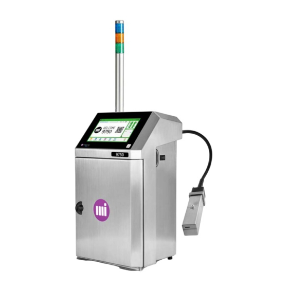
User manual | Description | 9750 Description Printer This printer was specially designed to be user-friendly and only provides the user with access to those parts that he needs to use on a daily basis. This printer includes a user interface with a 10-inch wide, diagonal colour touch screen, offers real-time display of the remaining printing capacity, consumption tracking, printing availability and maintenance procedures. - Page 9 User manual | Description | 9750 Overview 1 Printhead 2 Umbilical 3 Operator interface 4 Identification label (serial no.) 5 Umbilical outlet (the umbilical outlet may be positioned at 90°) 6 Handle for opening the door 7 Access door for consumable parts and maintenance modules 8 Electrical socket 9 ON/OFF switch 10 Access to hydraulic/electric/electronic components...
- Page 10 User manual | Description | 9750 Open door overview 12 Additive cartridge 13 Ink cartridge 14 Internal USB port 15 Module 4 - Air in filter IP56 (violet) 16 Module 3 - Recovery pump/Venturi 17 Module 2 - Filter for the primary ink 18 Manual maintenance valve 19 Module 1 - Pressure pump 20 Module 5 - IP56 air out filter (violet) or non-removable IP66 filter (depending on the version)
- Page 11 User manual | Description | 9750 Side view 1 Cell input M12 socket (black) 2 Encoder input M12 socket (blue) 3 Warning light output M12 socket (yellow) 4 Serial link RS232 connector M12 socket 5 Configurable I/O M12 socket 6 External USB port 7 Ethernet connector 8 Rear panel with Industrial interface card (4 cable glands - Serial/Parallel and Ethernet link) - Optional 9 Rear panel with Industrial interface card (4 cable glands - Serial/Parallel and Ethernet link + 24-pin con-...
-
Page 12: The Printing Module
User manual | Description | 9750 The printing module The printing module includes the umbilical (3 m or 6 m) and printhead (G or M). 1 Printhead 2 Umbilical outlet 3 Marker to indicate the position of the jet It is easy to place the head over the product to be printed. The engraved mark indicates the position of the jet. -
Page 13: Head Pressurisation Kit (Optional)
User manual | Description | 9750 Head pressurisation kit (optional) The head pressurisation kit is recommended when the printer will be used in dusty or damp envir- onments. The dry air supply maintains a consistent humidity inside the head, guaranteeing the smooth oper- ation of the printer and optimal print quality. -
Page 14: Standalone Compressor Kit (Optional)
User manual | Description | 9750 Standalone compressor kit (optional) The standalone compressor kit has the same pur- pose as the head pressurisation kit, but it is used when connecting to the air network is not possible. The kit is located inside the printer. To access the standalone compressor kit, after removing the cart- ridges and cartridge holders, remove the protective housing as shown in the figure. -
Page 15: Interface
User manual | Interface | 9750 Interface The printer is fitted with a fully tactile and interactive interface which adapts to each of the operator’s actions. Preview of the main screen The main screen is used for: checking printing checking the printer’s status viewing production information viewing the current print job accessing the various menus... - Page 16 User manual | Interface | 9750 1 Printer reports 2 Name of the job being printed 3 Coloured background. Printing status 4 Coloured bar. Printer information 5 External equipment connection indicator 6 Current date and time 7 Consumable part level indicator and access to more information 8 Access to production and operation information 9 Modification of the message in production by pressing and holding on the screen 10 Start/Stop printer...
-
Page 17: Interface Usage Principles
User manual | Interface | 9750 Interface usage principles Menu structure Organisation of the menu tree structure The printer’s three main functions are accessed from the main screen: Use and printing (1) Selecting, editing and managing jobs (2) Parameter settings and maintenance (3). Presentation of the menus Refer to your printer’s instruction... - Page 18 User manual | Interface | 9750 Navigation The buttons and fields used for operating the interface and navigating the menus are as fol- lows: Printing has started. One click pauses printing. Printing is paused. One click restarts printing. for parts & service call QLC (800) 837-1309 EN-10114031-AA 18/164...
- Page 19 User manual | Interface | 9750 Dialog boxes A dialog box is shown to inform the user or request confirmation: Close the dialog box and go back to the previous screen Cancel the action, go back to the previous screen Confirm the action Printer status The top left part of the screen shows the printer’s current status against a background col-...
-
Page 20: Consult Operating Information Of The Interface
User manual | Interface | 9750 Consult operating information of the interface Pressing the information zone (1) gives access to operating information (jet status, jet seed, motor speed, etc.). See section "Information" on page79/"History" on page81. Depending on its colour, the information bar can also be used to view any faults (3) or warnings (2) and provides direct access to a list of faults or warnings and how to resolve them. -
Page 21: Viewing A Job
User manual | Interface | 9750 Viewing a job The interface can be used for viewing a job’s preview clearly and easily. There are three different viewing sizes. Use the buttons to switch from one size to another. 1 The job is shown on the screen as it will be printed. The size of the job on the screen will be the same size printed. 2 The job preview is adjusted to the display area. - Page 22 User manual | Interface | 9750 If the preview is too big for the display area, scroll across the job using a finger. The red block on the view bar scrolls across according to the part of the job it is displaying. Use the buttons to move from one size to another or press and hold to edit the job.
-
Page 23: Use
User manual | Use | 9750 Starting up the printer To be able to start printing, the printer must be started up once it is switched on. Connect the printer to the mains power supply. Press the switch. The main screen will turn on after about 40 s. The printer is on but not started up. -
Page 24: Shutting Down The Printer
User manual | Use | 9750 Shutting down the printer Shutting down the printer corresponds to shutting down the ink circuit and jet. The touch screen interface is still available after the ink circuit has been shut down and the interface can be used. -
Page 25: Sending A Job For Printing
User manual | Use | 9750 Sending a job for printing Sending a job for printing means making the job ready for printing. From the main screen, press The currently selected job is highlighted in blue with this icon displayed in front of the job name in production. -
Page 26: Managing Consumables
User manual | Use | 9750 Managing consumables The remaining life and references of consumables are shown on the main screen. 1 Additive reference 2 Additive life remaining indicator 3 Additive life 4 Ink life 5 Ink life remaining indicator 6 Ink reference The ink life remaining varies depending on the number of characters in the job. - Page 27 User manual | Use | 9750 Statuses of life remaining indicators The indicators can show various status values depending on the remaining life of the con- sumable. Status of life remain- Colour Information/Action indicator Green Consumable OK. Green The cartridge should NOT be replaced. Green Level low.
-
Page 28: Various Behaviors Of The Consumables Used
User manual | Use | 9750 Various behaviors of the consumables used The table below shows a similar behavior for both consumables, but this behavior can appear separately for the ink or for the additive. STATUS COMMENTS/ACTIONS Markem-Imaje consumables have been Standard printer behaviour detected. -
Page 29: Information About The Consumables Used
User manual | Use | 9750 Information about the consumables used Press on the area of the screen dedicated to consumables: The following screen is displayed: 1 Ink cartridge information zone 2 Additive cartridge information zone 3 Ink/additive references detected. Black text: OK Red text: bad cartridge Other text: the inserted cartridge is not a Markem-Imaje cartridge... -
Page 30: Replacing A Consumable Cartridge
User manual | Use | 9750 Replacing a consumable cartridge Do not replace consumables unless a Consumable warning or fault is sig- nalled by the printer. Use only Markem-Imaje cartridges. Waste and consumables, see "Safety and important information", User Docu- mentation Center Markem-Imaje Faults reported by the printer are displayed in: a warning message (orange background) - Page 31 User manual | Use | 9750 Remove the cartridge (ink or additive) Unlock the cartridge Remove the empty cartridge from the cartridge holder for parts & service call QLC (800) 837-1309 EN-10114031-AA 31/164...
- Page 32 User manual | Use | 9750 Check the information on the new cartridge Insert the new cartridge Lock the cartridge for parts & service call QLC (800) 837-1309 EN-10114031-AA 32/164...
- Page 33 User manual | Use | 9750 Put the cartridge holder back in the printer Risk of puncture. When replacing the cartridges, do not touch the nozzle. Close the printer door. After the new ink cartridge is inserted, it empties partially into the printer's internal tank.
-
Page 34: Editing
User manual | Editing | 9750 Editing Usage profiles Profiles are used to manage access to the different menus/sub-menus, job modification levels and printer settings. Depending on the operators, it is possible to create 3 different profiles: 3 operator profiles The 3 operator profiles can have a password or no password. -
Page 35: Activating A Profile
User manual | Editing | 9750 Activating a profile The profile icon that can be seen on the main screen shows the currently activated profile. : the operator profile is activated (here Operator 1 profile). : the advanced profile is activated. To activate a different profile: Press the icon of the profile. -
Page 36: Configuring Usage Profiles
User manual | Editing | 9750 Configuring usage profiles Profiles can only be configured from the advanced profile. From the main screen, press Press Press Press Press the button of the profile to be configured. The configuration screen, shown with 6 categories, is displayed. -
Page 37: Managing Passwords
User manual | Editing | 9750 Managing passwords Passwords can only be managed from the advanced profile. Only uppercase Latin characters are allowed. Minimum number of characters: 1 Maximum number of characters: 20 From the main screen, press Press Press Press The password management screen appears. -
Page 38: Simple Modification (Modification In Production)
User manual | Editing | 9750 Simple modification (Modification in production) Principle (changing a text field) Simple modification mode is used to change the content of certain fields in a job. : Modify the current print job. : Access the selection list to modify another job. Pressing and holding on the screen allows you to modify the job currently being prin- ted. -
Page 39: Advanced Creation/Modification
User manual | Editing | 9750 Advanced Creation/Modification In simple modification, press to go to advanced modification. The editing screen in advanced modification alternates between two modes: Cursor mode Field mode Cursor mode To switch to field mode, select a field by clicking above. Field mode To return to cursor mode, click in the editing area outside of the fields OR press for parts &... -
Page 40: Cursor Mode: Move The Cursor, Add A Field And Define A Style
User manual | Editing | 9750 Cursor mode: move the cursor, add a field and define a style. This is the default mode if no field has been selected. In cursor mode, a red cursor flashes in the editing field and there are red arrows around the editing field. In this mode, the fol- lowing actions are possible: Moving the cursor Defining a field’s font style before creating it... - Page 41 User manual | Editing | 9750 To view all the fields (icons) when they are shown stacked, swipe the icon bar to the left: Defining a field’s font style before its creation In cursor mode, the font style applied at the cursor position is shown in red in the top right corner of the screen.
- Page 42 User manual | Editing | 9750 Approximate movement:\\ Select the field to move by clicking above; Press a 2nd time and hold down in the field and use the finger to drag it to the desired position. By dragging the field towards a marker line, it will automatically be aligned with it by magnetism.
- Page 43 User manual | Editing | 9750 the bolderisation of the characters. The font sizes available will depend on the choice of font. The style changes made in the field are shown. Press once the modifications are complete. Delete a field Press the field concerned to select it.
-
Page 44: Modifying A Job (Advanced Modification)
User manual | Editing | 9750 Modifying a job (Advanced modification) : Modify the current print job. : Access the selection list to modify another job. Pressing and holding on the screen allows you to modify the job currently being prin- ted. -
Page 45: Creating A Job
User manual | Editing | 9750 Creating a job A job is made up of different types of fields. Each field type corresponds to a data type (text, date, counter, etc.). From the main screen, press From the job selection screen, press Enter the name of the new job. - Page 46 User manual | Editing | 9750 the number of marker lines defines the default font used in the job. The choice of number of marker lines depends on the algorithm or on the speed selected. With a multi-line algorithm, the number of marker lines is fixed. Press to confirm the default settings or the new settings.
-
Page 47: For Parts & Service Call Qlc (800) 837-1309 Modifying Job Parameters
User manual | Editing | 9750 Modifying job parameters The job parameters can be accessed using the following paths from the main screen: ► ► ► ► ► 1 Head direction 2 Product speed 3 Speed measurement 4 Triggering Head direction Setting this parameter depends on the installation of the printer on the production chain and on the desired result when read. - Page 48 User manual | Editing | 9750 If you select a particular algorithm, the printer will offer a selection of appropriate fonts but the maximum speed will be fixed. The editing area is determined by the selected speed and algorithm. Depend- ing on the settings, certain zones may not be printable.
- Page 49 User manual | Editing | 9750 Manual trig This setting allows the "Manual trig" button to be displayed in the icon bar of the main screen. Select "yes" to display the Trig button: The icon appears in grey when the printer is off. Unit This setting is used to define the unit of the Forward Margin, Return Margin and Repeated Interval values.
- Page 50 User manual | Editing | 9750 The setting applied by default to all jobs can be modified in: ► ► ► for parts & service call QLC (800) 837-1309 EN-10114031-AA 50/164...
-
Page 51: Saving A Job
User manual | Editing | 9750 Saving a job To implement the modifications made to a job, press A request to confirm overwriting appears. Pressing on YES validates the modifications to the job. Pressing on NO displays the job name. To create a new job using the changes, enter a different name before validating. -
Page 52: Deleting A Field
User manual | Editing | 9750 Deleting a field From the main screen, press Press Press Press Press to access the job selection list. Select the job to be deleted. Possibility to select all jobs by Possibility to deselect all jobs by The job cannot be deleted during printing. -
Page 53: Creating/Modifying The Printing List
User manual | Editing | 9750 Creating/Modifying the printing list The printing list contains the jobs that may be selected for printing via an external link. It is created from the main list of jobs in the printer’s memory. It can contain up to 255 mes- sages. - Page 54 User manual | Editing | 9750 Press one or more jobs to select or deselect them. Press to exclude the jobs selected from the printing list. The up and down buttons can be used to move the job in the printing list. The number shown will be used by the external link to identify the job.
-
Page 55: Entering Chinese Characters
User manual | Editing | 9750 Entering Chinese characters Chinese characters may be entered using the Pinyin entry method or directly using the Chinese keyboard. Pinyin entry method Define the field’s font style before its creation. When creating a text field, press to access the Chinese keyboard. -
Page 56: Setting The Tacho Step
User manual | | 9750 Setting the Tacho step The process for configuring the production mode requires the Tacho step to be set prop- erly. Theoretical Tacho step calculation The Tacho step must be specified properly. The calculation depends on the system installed (type of encoder and wheel diameter). -
Page 57: Adding/Modifying A Field
User manual | Adding/Modifying a field | 9750 Adding/Modifying a field Adding/Modifying a Text field Define the field’s font style before its creation. From the editing screen, place the cursor at the desired position. Press to add a Text field. Enter the text. - Page 58 User manual | Adding/Modifying a field | 9750 The preview shows the new date calculated. Press to insert the date in the job. The new Date field is shown in the job. Modify the date format Press To add an element at the cursor position, select it from one of the dropdown lists under- neath: Day, Month, Years, Week, Separator.
- Page 59 User manual | Adding/Modifying a field | 9750 mmm: month of the year (first three letters) for Dates 2 to 6. mmm1: month of the year in language 1 (first three letters) mmm2: month of the year in language 2 (first three letters) y: last digit of the year (0 to 9) yy: last two digits of the year (between 00 and 99) yyyy: the four digits of the year (from 0001 to 9999)
- Page 60 User manual | Adding/Modifying a field | 9750 The default settings applied to Date fields in all jobs can be modified in: ► ► ► Modifying the printer’s Date variable settings ► ► ► ► First day of the week Used to define the first day of the week.
-
Page 61: Add/Modify A Time Field
User manual | Adding/Modifying a field | 9750 Add/Modify a Time field Place the cursor at the desired position. Press to add a Time field at the cursor’s position. Define the field’s font style before its creation. Use the blue arrows to move within the time preview. Click on to remove the element preceding the cursor. - Page 62 User manual | Adding/Modifying a field | 9750 f Select the batch value, between 0 and 999,999. This is the number of items in a batch. The counter is incremented when the batch value is reached. For example, if the batch value is set to 5, the counter will only increment by the counter step value after 5 items have been detected.
-
Page 63: Add/Modify A Counter Field
User manual | Adding/Modifying a field | 9750 Add/Modify a Counter field Define the field’s font style before its creation. Place the cursor at the desired position. Press to add a Counter field at the cursor’s position. The preview line summarises the counter’s characteristics. Access the Counter field parameters When the Counter field is unlocked: in simple modification mode, the counter can only be reset to its starting value or any other value. - Page 64 User manual | Adding/Modifying a field | 9750 If the counter selected is already being used in another job, its characteristics will be replaced by the default settings. For this reason, if the same counter has to be used in more than one job, it is recommended that its char- acteristics are defined as the default settings.
- Page 65 User manual | Adding/Modifying a field | 9750 Select the batch value, between 0 and 999,999. This is the number of items in a batch. The counter is incremented when the batch value is reached. For example, if the batch value is set to 5, the counter will only increment by the counter step value after 5 items have been detected.
-
Page 66: Adding/Modifying An External Variable Field
User manual | Adding/Modifying a field | 9750 Adding/Modifying an External variable field This type of field is used to reserve locations in a job for variable information to be trans- mitted by an external RS232/V24 or RS422 link (e.g. weight from a weighing machine, information from a PLC or from a barcode reader). -
Page 67: Adding/Modifying A Symbol Field
User manual | Adding/Modifying a field | 9750 Adding/Modifying a Symbol field A symbol can be inserted into a job. This is a special shape, a drawing or a logo. To make a symbol available, it must first be imported to the printer using the Transfer font/symbol function. -
Page 68: Adding/Modifying A Time Stamp Field
User manual | Adding/Modifying a field | 9750 Adding/Modifying a Time stamp field A time stamp field enables time and date variables, pre-coded in the time stamp table, to be inserted in the job: ► ► ► ► Place the cursor at the desired position. Press to add a Time Stamping field at the cursor’s position. - Page 69 User manual | Adding/Modifying a field | 9750 In any given Time Stamp table, all boxes contain the same number of char- acters as the longest box. If a box needs to contain fewer characters than the longest box, the missing characters will be replaced with spaces. for parts &...
-
Page 70: Adding/Modifying A Barcode Field
User manual | Adding/Modifying a field | 9750 Adding/Modifying a Barcode field This field type is used to transcribe miscellaneous fixed or variable information as bar- codes. Various types of barcodes are available for use in a job. A job may contain up to four Barcode fields. - Page 71 User manual | Adding/Modifying a field | 9750 Height Select a height value from the list of available values. The height is expressed in dots and is limited to the height of the fonts present. For EAN8, EAN13, UPCA, UPCE barcodes, if the plain text option is selected, the fol- lowing heights can be configured: height of the barcode, spacing between the plain text and the barcode, font height used for the plain text (subject to fonts available).
- Page 72 User manual | Adding/Modifying a field | 9750 The default settings applied to the Barcode fields for all jobs can be modified ► ► ► . A default barcode type can be defined, with asso- ciated settings. Barcode characteristics 2/5 interleaved This barcode may only be used to represent numerical characters.
- Page 73 User manual | Adding/Modifying a field | 9750 GS1-128 GS1-128 is used in traceability applications and for the purpose of improving supply chain safety and durability. The GS1-128 barcode is a variation of the 128 Code. This barcode is not designed to be read at retail store checkouts.
- Page 74 User manual | Adding/Modifying a field | 9750 Example: the AI (02) must be followed by the AI (37). Other AIs can never be used together, for example the AI (01) and the AI (02). Other AI: If an AI is not available in the predefined list, it can be entered manually.
- Page 75 User manual | Adding/Modifying a field | 9750 "Adding bold" setting 2 Printed code height (number of drops) Printed code width (number of drops) The Datamatrix contains a margin (Quiet zone). This is a blank area on all sides of the Datamatrix that must not contain any graphic elements likely to interfere with barcode read- ing.
- Page 76 User manual | Adding/Modifying a field | 9750 When you use QR code module 21x21 with correction level M, for example, the maximum numbers allowed are respectively 128, 34, 20, 14, 8 for data bits, numeric figures, alpha- numeric values, Binary and Kanji. The available settings ar: Bolderization, Error correction (correction level L, M, Q or H), Quiet zone (margin) and Code page (UTF-8).
-
Page 77: Adding/Modifying A Shift Code Field
User manual | Adding/Modifying a field | 9750 Adding/Modifying a Shift code field A shift code is used to print recurring time information over a daily period. The code is defined based on a starting time and an interval duration. A job may include one shift code. - Page 78 User manual | Adding/Modifying a field | 9750 alphabetic, 26 letters alphabetic, 24 letters (excluding I and O) numeric Press a box to modify it, and enter a new value using the keyboard that is displayed. Once the box has been modified, the new value can be copied to all boxes by pressing for parts &...
-
Page 79: Information
User manual | Information | 9750 Information Information zone and information screen Information zone and printer status information screen The information zone shows two pieces of information on the main screen: The counter of printed messages (Print count) The number of messages still possible to be printed. (Job left) Pressing this zone shows the printer status and operating settings in real time. - Page 80 User manual | Information | 9750 The installation date The EHT level The total number of prints counter The software version Operating history information ► ► ► This function is used to view a record of the machine settings every 10 minutes in normal operation.
-
Page 81: History
User manual | History | 9750 History Printer history The interface gives access to a history of various data about the printer (printing, main- tenance, availability/consumption and warnings/faults). Printing history ► ► ► This history screen shows jobs printed over the last two months. For each job, the fol- lowing are displayed: the period in which it was printed and the number of prints counted. - Page 82 User manual | History | 9750 the kit identification number (batch number). Maintenance actions must be saved in ► ► ► to be shown in the history. Pressing transfers the data being displayed onto an external medium. Each transfer file includes the main printer configuration data and the data being displayed. After the transfer is selected , a transfer confirmation message is displayed.
- Page 83 User manual | History | 9750 Consumables history ► ► ► This history shows the information from the last 100 cartridges (50 ink/50 additives) used by the printer. This function is used to view: Date Time Reference of the ink or additive Counter Batch number Expiration date...
-
Page 84: Troubleshooting
User manual | Troubleshooting | 9750 Troubleshooting Controlling warnings and faults Description of the Alarms and Faults screens :In certain cases, gives access to a warning or fault resolution wizard. :Clear the warning or fault Pressing takes you to the next screen: Summary of the warning/fault in the information bar: for parts &... - Page 85 User manual | Troubleshooting | 9750 Pressing the coloured area displays the list of defects or alarms: Pressing will resolve the alarm or fault. (Access the troubleshooting procedure) Pressing will acknowledge all warnings and faults on the list. Certain preventive maintenance warnings cannot be acknowledged without following a specific procedure (see the Maintenance section).
-
Page 86: List Of Warnings And Faults
User manual | List of warnings and faults | 9750 List of warnings and faults Fault resolution wizard The interface proposes a detailed procedure for resolving certain warnings and faults. Just follow the steps shown on the screen: The warning or fault will be cleared automatically once it is resolved List of warnings and faults D: Fault Description... - Page 87 User manual | List of warnings and faults | 9750 D: Fault Description A: Alarm 4080 Additive transfer pump blocked (P2) 4090 Drain pump blocked (P3) 4100 Technology roadmap: electronic fault 4110 Technology roadmap: solenoid valve power supply fault 4120 Drainage fault 4130 Level sensor outside of specifications...
- Page 88 User manual | List of warnings and faults | 9750 D: Fault Description A: Alarm 5010 Time out on print unit initialization 5020 Unable to save production settings 5030 Invalid printer settings file (Use Default) 5040 Unable to save printer settings 5050 Printer initialization FAILURE 5060...
-
Page 89: Diagnostic Wizard
User manual | Diagnostic wizard | 9750 Diagnostic wizard Preliminary checks Various preliminary checks must be performed before searching for defective items. These enable problems such as dirty parts, ink leaks or poor electrical connections to be detected visually. External appearance Subassemblies to check Possible anomalies □... -
Page 90: Troubleshooting Chart
User manual | Troubleshooting chart | 9750 Troubleshooting chart Malfunction Actions and solutions 1- Screen off. 1a- Check the mains power supply. 1b- Check the power cord and connection. 2- Time/Date corrupted The date is reset to 01/01/2008. 2a- Enter the right date and time. 2b- Contact Markem-Imaje Technical Support. - Page 91 User manual | Troubleshooting chart | 9750 18a- Clean and dry the printhead. 18b- Use the “Unblock Nozzle” function in the head operations screen. 19a- Drain the printer according to the procedure described in 19- Ink level too high this manual. 20a- Check that the ink used corresponds to the printer’s con- 20- Viscosity too high figuration.
- Page 92 User manual | Troubleshooting chart | 9750 ations on the cell(s) and encoder. 32a- Clean the printhead (including the cover) and check that 32- Poor printing quality there are no obstacles on the jet trajectory. 32b- Check the stability of the head bracket (no vibrations). 32c- Check the head/object distance (examples 1 and 2).
-
Page 93: Maintenance
User manual | Maintenance | 9750 Maintenance Description of the print head components Description of the G and M head Modulation chamber Charge electrode Stroboscopic LED Deflection plates Gutter for parts & service call QLC (800) 837-1309 EN-10114031-AA 93/164... -
Page 94: Removing The Head Cover
User manual | Maintenance | 9750 Removing the head cover Position the head on its stand. Loosen the knurled screw and remove the head cover. for parts & service call QLC (800) 837-1309 EN-10114031-AA 94/164... -
Page 95: Regular Maintenance
User manual | Maintenance | 9750 Regular maintenance You must perform periodic maintenance on your printer. Monitoring your printer and per- forming maintenance on it are essential in ensuring that it remains in good condition. Forgetting or not doing maintenance can lead to bigger and more expensive failures. The frequency of maintenance will depend on the type of use: 30 months or 18,000 hours from the date the printer was first used, whichever comes first. -
Page 96: Cleaning The G Head And The M Head
User manual | Maintenance | 9750 Head cleaning Head movement Pigmented/micro pigmented ink Standard dye ink G Head Every week Every week Every two weeks M Head Every week Every week Every two weeks Enhanced head cleaning: see "In-depth G Head cleaning " on the next page. See the Spare Parts catalogue for the maintenance components. -
Page 97: In-Depth G Head Cleaning
User manual | Maintenance | 9750 In-depth G Head cleaning This type of cleaning is required for certain inks, or if the printer is used in harsh envir- onments (high temperatures, dusty atmospheres). Equipment required: Protective goggles Latex gloves Maintenance tray Spray bottle Squeeze blower Fiche A47081... - Page 98 User manual | Maintenance | 9750 Clean Clean for parts & service call QLC (800) 837-1309 EN-10114031-AA 98/164...
- Page 99 User manual | Maintenance | 9750 Inserting additive 10 s Stability control 20 s for parts & service call QLC (800) 837-1309 EN-10114031-AA 99/164...
- Page 100 User manual | Maintenance | 9750 Press to restart the jet. Closing the head cover again. Clear the cover fault if necessary by pressing for parts & service call QLC (800) 837-1309 EN-10114031-AA 100/164...
-
Page 101: In-Depth M Head Cleaning
User manual | Maintenance | 9750 In-depth M Head cleaning This type of cleaning is required for certain inks, or if the printer is used in harsh envir- onments (high temperatures, dusty atmospheres). Equipment required: Protective goggles Latex gloves Maintenance tray Spray bottle Squeeze blower Fiche A47081... - Page 102 User manual | Maintenance | 9750 Clean for parts & service call QLC (800) 837-1309 EN-10114031-AA 102/164...
- Page 103 User manual | Maintenance | 9750 Inserting additive 10 s Stability control 20 s for parts & service call QLC (800) 837-1309 EN-10114031-AA 103/164...
- Page 104 User manual | Maintenance | 9750 Press to restart the jet. Closing the head cover again. Clear the cover fault if necessary by pressing for parts & service call QLC (800) 837-1309 EN-10114031-AA 104/164...
-
Page 105: Starting Up The Jet
User manual | Maintenance | 9750 Starting up the jet After a maintenance, head cleaning or manual jet shutdown operation, proceed as follows to restart the jet. To access the Head Maintenance screen, press ► The jet’s status is shown at the top left of the screen. The jet is off. -
Page 106: Jet Troubleshooting
User manual | Maintenance | 9750 Jet troubleshooting Equipment required: Protective goggles Latex gloves Spray bottle Squeeze blower Eyeglass If the jet is absent or deviated, various actions are used to re-center it in the gutter: To access the Head Maintenance screen, press ►... - Page 107 User manual | Maintenance | 9750 Clean the head (see the head cleaning procedure"Cleaning the G head and the M head " on page96). After cleaning the head, restart the jet (see the jet start-up procedure"Starting up the jet" on page105). Check that the jet is in the gutter.
-
Page 108: Adjust The Break-Off Point
User manual | Maintenance | 9750 Adjust the break-off point If the printing is poor quality or if the printer detects faults, it may be necessary to adjust the break-off point. Press then ► ► ► to go to the screen for adjusting the jet break-off point ( Position the head on the maintenance stand. -
Page 109: Performing A Printing Test
User manual | Maintenance | 9750 Performing a printing test The printer status screen can be used to perform a printing test. Press the information zone. Press to run a printing test In single trigger mode, the printing test stops automatically after the job has been printed once. -
Page 110: Inhibiting Certain Faults
User manual | Maintenance | 9750 Inhibiting certain faults The screen enabling certain printer faults to be inhibited is accessible from the main screen as follows: ► ► ► ► During some servicing and maintenance operations it may be desirable to inhibit checks for certain faults. -
Page 111: Procedure For Changing The Modules 1 To 6
User manual | Maintenance | 9750 Procedure for changing the modules 1 to 6 The ink circuit is made up of several modules. Each module performs one or more func- tions in the ink circuit. Preventive maintenance requires that all modules 1 to 5 be replaced. Module change frequency: refer to the table at the beginning of this chapter"Regular main- tenance"... - Page 112 User manual | Maintenance | 9750 Description of the preventive maintenance kit Module 1: Pressure pump Module 2: Filter for the primary ink Module 3: Recovery pump/Venturi Module 4: Air in filter Module 5: Air out filter IP56 (violet) Gloves Empty cartridge for parts &...
-
Page 113: Ink Pressure Pump - Module 1
User manual | Maintenance | 9750 Ink pressure pump - Module 1 ENM10110977 Start of the draining procedure for replacing the modules This procedure should be performed before replacing modules 1, 2, 3 or 6, or during pre- ventive maintenance. ►... - Page 114 User manual | Maintenance | 9750 Fig. A Press The module draining sequence then starts automatically. Put the module back in place. Follow the replacement procedure in the next paragraph. Replacing module 1: Pressure pump Unscrew the 3 CHc M4 screws (a) (Fig.B) Fig.B Remove module 1.
- Page 115 User manual | Maintenance | 9750 After replacing a module, press Remove the ink cartridge (waste), Put the additive cartridge back in place, Clean the printhead. As waste, the module must be managed in compliance with local regulations related to waste management and transport of dangerous goods. At the end of the module replacement procedure : Using the 3 mm Allen key, move the valve to the "Operation"...
-
Page 116: Ink Filter - Module 2
User manual | Maintenance | 9750 Ink filter - Module 2 ENM10107952 Start of the draining procedure for replacing the modules This procedure should be performed before replacing modules 1, 2, 3 or 6, or during pre- ventive maintenance. ► ►... - Page 117 User manual | Maintenance | 9750 Fig. A Press The module draining sequence then starts automatically. Put the module back in place. Follow the replacement procedure in the next paragraph. Replacing module 2: Ink filter Unscrew the 4 CHc M4 screws (a): for parts &...
- Page 118 User manual | Maintenance | 9750 Pivot the module: Unlock the module and pull it forward to remove as shown in the figure below: Remove the protection from the new module: Clean the bearing surface before installing the new module. Reassemble the module by carrying out the removal steps in reverse.
- Page 119 User manual | Maintenance | 9750 Put the additive cartridge back in place, Clean the printhead. As waste, the module must be managed in compliance with local regulations related to waste management and transport of dangerous goods. At the end of the module replacement procedure : Using the 3 mm Allen key, move the valve to the "Operation"...
-
Page 120: Ink Vacuum Pump - Module 3
User manual | Maintenance | 9750 Ink vacuum pump - Module 3 ENM10109440 Module 2 must be disassembled to access module 3. Start of the draining procedure for replacing the modules This procedure should be performed before replacing modules 1, 2, 3 or 6, or during pre- ventive maintenance. - Page 121 User manual | Maintenance | 9750 Fig. A Press The module draining sequence then starts automatically. Put the module back in place. Follow the replacement procedure in the next paragraph. Replacing module 3 - Recovery pump/Venturi Place a sheet of paper towel or the wipe supplied with the module kit under the module and unscrew the 4 CHc M4 screws (a): Fig.B Remove module 3.
- Page 122 User manual | Maintenance | 9750 Put module 2 back in place After replacing modules, press Remove the ink cartridge (waste), Put the additive cartridge back in place, Clean the printhead. At the end of the module replacement procedure : Using the 3 mm Allen key, move the valve to the "Operation"...
-
Page 123: Module 4-Inlet Air Filter
User manual | Maintenance | 9750 Module 4-Inlet Air filter ENM10094182 Replacing module 4: Air in filter Fig.A Fig.B Remove the filter and its holder by pressing into the two front notches of the filter while pulling down. (Fig.A then B) Put the new filter and its holder in place of the old one in the direction of assembly indic- ated on the front of the filter holder. -
Page 124: Hydraulic Module - Module 6
User manual | Maintenance | 9750 Hydraulic module - Module 6 ENM10110531 Start of the draining procedure for replacing the modules This procedure should be performed before replacing modules 1, 2, 3 or 6, or during pre- ventive maintenance. ► ►... - Page 125 User manual | Maintenance | 9750 Before starting step 3 of the procedure, move the valve to the maintenance position. Using the 3 mm Allen key, move the valve to the "Maintenance" position (Fig. A): Fig. A The module draining sequence then starts automatically. Put the module back in place.
- Page 126 User manual | Maintenance | 9750 Fig.B Pull module 6 forward to remove it. (Fig.C) Fig.C Replace the module with a new one. Reassemble by carrying out the removal steps in reverse. Make sure that the seals on module 6 are present. Insert the cartridge holders and the ink/additive cartridges.
- Page 127 User manual | Maintenance | 9750 This maintenance procedure must be recorded in the ► ► ► function for optimal tracking of the printer. for parts & service call QLC (800) 837-1309 EN-10114031-AA 127/164...
-
Page 128: Drain And Rinse The Ink Circuit (Full Draining And Flushing Of The Ink Circuit)
User manual | Maintenance | 9750 Drain and rinse the ink circuit (full draining and flushing of the ink circuit) Equipment required: Protective goggles Latex gloves Draining/flushing kit The ink circuit must be fully drained and flushed in the following cases: - Shutdown for more than 15 days;... - Page 129 User manual | Maintenance | 9750 Install the drain kit as shown in the following figure: A: insert the tip of the kit in place of the ink cartridge B: lock the tool on the cartridge holder for parts & service call QLC (800) 837-1309 EN-10114031-AA 129/164...
- Page 130 User manual | Maintenance | 9750 Connect the hose (a) to the drum of the draining kit (b) The hose (a) must be inserted no more than 8 cm inside the drum (b) Click on to go to the next stage. Insert a full additive cartridge (c): Click on to go to the next stage.
- Page 131 User manual | Maintenance | 9750 Position the print head on the maintenance stand. Press . The draining/flashing operation will then start automatically. The operation is completed in step 12: Press then press Remove the empty additive cartridge Remove the tip from the ink cartridge holder kit Close the drum with the new undrilled cap Dispose of the waste drum Replace the cartridge holders with a full ink cartridge and a full additive cartridge...
-
Page 132: Testing The Ink Circuit
User manual | Maintenance | 9750 Testing the ink circuit Certain maintenance and troubleshooting operations require ink circuit components to be tested. The printer must be shut down. ►►► The screen may be different, depending on your configuration. When this function is enabled, the printer is placed in standby. It should be restarted with button once the operations have been completed. - Page 133 User manual | Maintenance | 9750 : pump stopped; : pump in operation The pressure, pump rotation or flow values are also displayed in real time on this ink circuit screen. To facilitate these operations, the main operating settings (pressure, pump rotation or flow values) and the level of the measuring tank are displayed in real time.
-
Page 134: Printer Configuration
User manual | Printer configuration | 9750 Printer configuration Setting the date and time Setting the date Press ► ► ► ► to access the Date screen. Press to choose the month and year. Select the day from the calendar. Press to confirm. -
Page 135: Defining Or Modifying A Screensaver
User manual | Printer configuration | 9750 Defining or modifying a screensaver Press ► ► ► ► Press and select a screensaver from the pull-down list. Press to set the time before the interface goes into standby. Press to confirm. The screensaver is displayed if the printer is inactive for the tome set in the "Time out"... - Page 136 User manual | Printer configuration | 9750 Select "Generic input" or "Generic output" and then assign an item from the list. Press to confirm. for parts & service call QLC (800) 837-1309 EN-10114031-AA 136/164...
-
Page 137: Configuring The Parent/Child Function
User manual | Printer configuration | 9750 Configuring the Parent/Child function To select the same job (with the same parameters) for production on several networked printers, one of the printers must be identified as a “Parent” printers and the others as “Child”... -
Page 138: Configuring Network Connections
User manual | Printer configuration | 9750 Configuring network connections Configuring the serial links Press ► ► ► ► ► Select: transmission speed (in baud): 9600 - 19200 - 38400 - 57600 - 115200, number of data bits type of parity: none, even or odd number of stop bits: 1 or 2 The protocol (see next page). - Page 139 User manual | Printer configuration | 9750 Selecting the protocol Press ► ► ► ► ► The printer is capable of handling various protocols corresponding to various types of external links (depending on its configuration) From the Ethernet or Serial link 1 or 2 configuration screen, select one of the five pro- tocols proposed: Standard Job name selection –...
- Page 140 User manual | Printer configuration | 9750 < STX (02h) >< N(4Eh) > < MessageName (hexa) > < ETX (03h) > Ex: 02 4E 4D 45 53 53 31 03 => To select a message named "MESS1" M MsgNumber: Library message selection by number <...
-
Page 141: Transferring Data
User manual | Transferring data | 9750 Transferring data Press ► ► This function transfers data between the printer and an external medium: USB drive. Open the printer door to access the USB port. Various types of data can be transferred: jobs, fonts, symbols, algorithms, languages. Production is stopped before starting the transfer. - Page 142 User manual | Transferring data | 9750 Select: source medium target medium, if necessary destination directory if the medium has one Languages may only be transferred from an external medium to the printer. Confirm by pressing . The contents of the source medium are displayed. Select one or more directories or data items to transfer.
-
Page 143: External Connections
User manual | External Connections | 9750 External Connections General information The printer is connected to the surrounding environment via an industrial interface com- prising an industrial interface board and dedicated connectors. Rear door open with the industrial interface card (a): Various types of signals may be exchanged: –... -
Page 144: External
User manual | External Connections | 9750 External The wiring for these signals may be connected: 1 industrial interface board terminals (optional) 2 24-pin connector (optional) 3 IP65 sealed M12 sockets (optional) (1 ) Either to the terminal blocks on the industrial interface board (optional), with cables routed via IP65 sealed cable glands (located on the rear panel of the printer). -
Page 145: Marking Of Industrial Interface Board Terminals
User manual | External Connections | 9750 Marking of industrial interface board terminals for parts & service call QLC (800) 837-1309 EN-10114031-AA 145/164... - Page 146 User manual | External Connections | 9750 Terminals Name Description TXD-1 Serial link 1 (V24/RS232C): data output RTS-1 Serial link 1 (V24/RS232C): Request To Send RXD-1 Serial link 1 (V24/RS232C): data input Serial link 2 (RS422): data input RXD-2- TXD-2- Serial link 2 (RS422): data output RXD-2+ Serial link 2 (RS422): data input...
- Page 147 User manual | External Connections | 9750 TRIGG-b Start printing/top object (Cell 1) D7-a Job selection by parallel interface D6-a Job selection by parallel interface D5-a Job selection by parallel interface D4-a Job selection by parallel interface D3-a Job selection by parallel interface D2-a Job selection by parallel interface D1-a...
- Page 148 User manual | External Connections | 9750 Terminals Name Description Common +24 V COUNTR RESETx-a Counter reset set with input x COUNTR RESETy-a Counter reset set with input y COUNTR RESETx-b Counter reset set with input x COUNTR RESETy-b Counter reset set with input y STOP PRINT-a Cancel printing ON/OFF-a...
- Page 149 User manual | External Connections | 9750 OUT-3- Not assigned ALARM+ Alarm: optocoupled output COUNTR END+ Counter end value ALARM- Alarm: optocoupled output COUNTR END- Counter end value OUT-1+ Not assigned OUT-2+ Not assigned OUT-1- Not assigned OUT-2- Not assigned for parts &...
-
Page 150: Operating Characteristics
User manual | External Connections | 9750 Operating Characteristics Printing and counter connections Inputs The input circuits have the characteristics of a high speed photocoupler with an isolation voltage of 3 kV. They are protected against overvoltage and against polarity inversions. Operating voltage 5 to 35 V Regulated input current within the operating voltage range Current consumed 5/6 mA (encoder 12/13 mA) -
Page 151: Printing
User manual | External Connections | 9750 Printing Object detection cell inputs (TRIG/CELL2) The object detector are connected to the black M12 socket or to the industrial interface board’s TRIG-a and TRIG-b terminals. When the detector is activated by a passing object, it sends a signal to the printer which triggers printing. -
Page 152: Counter
User manual | External Connections | 9750 Counter Counter reset input (COUNTR RESETx/COUNTR RESETy) Two counters can be configured to be reset to their starting values by the COUNTR RESETx and COUNTR RESETy inputs. A pulse on the corresponding input resets the counter to its initial value. - Page 153 User manual | External Connections | 9750 Direct selection by job number (MODE = 0) Terminals D0, D1, D2, D3, D4, D5, D6 and D7 are used to address the job number (hexa- decimal) selected for printing. The INC/TRG MESS signal confirms the job number present in the data D0 to D7. Selection by job number incrementation (MODE = 1) The job is selected using the LIBRARY SENSE and INC/TRG MESS inputs.
-
Page 154: Warnings And Faults
User manual | External Connections | 9750 Warnings and faults Warning output This output signals a non-critical printer malfunction which does not prevent printing. The warning is generated to attract the operator's attention so that the anomaly can be cor- rected. -
Page 155: Other Functions
User manual | External Connections | 9750 Alarm/Fault/Generic Input/Output configuration screen: Notification of the printer's status by a warning light For machines equipped with a light beacon (green, blue, yellow): The green light indicates normal conditions. (A) The blue light indicates a condition that requires operator action. (B) The yellow light indicates an abnormal condition, the emergence of a critical condition. - Page 156 User manual | External Connections | 9750 Contact your Markem-Imaje retailer. for parts & service call QLC (800) 837-1309 EN-10114031-AA 156/164...
-
Page 157: M12 Connector Pinouts
User manual | External Connections | 9750 M12 connector pinouts The photocell and encoder inputs and the Warning/Fault output are available via female M12 connectors located on the left of the printer. The pins on these connectors are numbered as follows: Photocell input (black connector) 24 V TRIGG-b... - Page 158 User manual | External Connections | 9750 Wiring of the Generic M12 I/O connector 1 BN 5 PK 9 2 BU 6 YE 10 VT 3 WH 7 BK 11 GY/PK 4 GN 8 GY 12 RD/BU M12 Connector Pinout Description/Désignation Name/Nom Pin 1...
-
Page 159: Technical Specifications
User manual | Technical Specifications | 9750 Technical Specifications Printing functions Single-jet print head G head (printing Resolution: 71 dpi) M head (printing Resolution: 115 dpi) Up to 5 lines of printing Printing speed: up to 6.6 m/s Font height from 5 to 32 points Character height: from 1.2 to 11.2 mm Wide selection of 1D and 2D barcodes: EAN 8/EAN 13/UPCA/UPCE barcodes, code 39, 2 of 5 interlaced, Datamatrix, QRcode, Dotcode... - Page 160 User manual | Technical Specifications | 9750 Other characteristics Weight: 25 kg Table top or vertical mounting 3-metre ultra-flexible umbilical cable Stainless steel housing and print head housing Dust/water protection rating: IP56 not requiring factory air Operating temperature range: 32°F to 122°F (0°C to 50°C) depending on ink used Humidity: 10 to 90% without condensation Power supply: 100-240 V;...
-
Page 161: Printer Dimensions
User manual | Printer dimensions | 9750 Printer dimensions for parts & service call QLC (800) 837-1309 EN-10114031-AA 161/164... - Page 162 User manual | Print head dimensions | 9750 Print head dimensions units: [inch] for parts & service call QLC (800) 837-1309 EN-10114031-AA 162/164...
- Page 163 User manual | Revision | 9750 Revision Revision AA is the first version of this manual. The Revision index changes with each update. Date issued Documentation revision index 04/2022 For Marking & Coding Equipment. Photographs and drawings are not binding in detail. This document was originally written in French.
- Page 164 Markem-Imaje Industries 9, rue Gaspard Monge 26500 Bourg-lès-Valence France for parts & service call QLC (800) 837-1309 Tel. : +33 (0)4 75 75 55 00 www.markem-imaje.com 9750User manual - 10114031 -AA | 4/6/2022...
Need help?
Do you have a question about the markem-imaje 9750 and is the answer not in the manual?
Questions and answers
additive cartridge is not detected
The additive cartridge may not be detected on the Dover 9750 for the following reasons:
1. The cartridge is not properly inserted.
2. The cartridge is not a compatible Markem-Imaje consumable.
3. The cartridge has expired or is defective.
If the reference numbers are greyed out and the cartridge is not recognized, check insertion and compatibility. If the issue persists, the cartridge batch may be defective.
This answer is automatically generated