Table of Contents
Advertisement
Quick Links
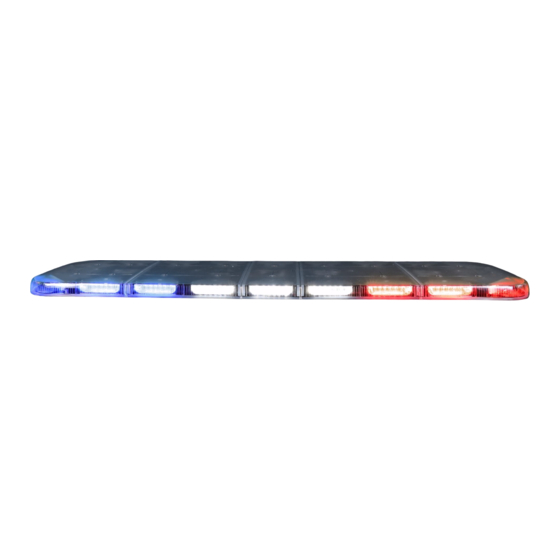
nFUSE™ LED Lightbar
F
E
IMPORTANT NOTICE TO INSTALLER: Make sure to read and understand all
instructions and warnings before proceeding with the installation of this product.
Ensure that the manual and any warning cards are delivered to the end user of
D
this equipment. Proper installation of the lightbar requires the installer to have
a thorough knowledge of automotive electronics, systems, and procedures.
Lightbars provide an essential function of an effective visual warning system.
The use of the lightbar does not insure that all drivers can or will abide by or
C
react to an emergency warning signal, especially at high rates of speeds or
long distances. The operator of the vehicle must never take the right of way for
granted and it is the operator's responsibility to proceed safely. The effectiveness
B
of the lightbar is highly dependant on the correct mounting and wiring. The
installer must read and follow the manufacturer's installation instructions and
warnings in the manual. The vehicle operator should verify daily that the lightbar
GASKET MOUNTING INSTRUCTIONS
is securely fastened to the vehicle and properly functioning before operating
A
vehicle. The lightbar is intended for use by authorized personnel only. It is the
user's responsibility to ensure they understand and operate the emergency
warning devices in compliance with the applicable city, state and federal laws
and regulations. SoundOff Signal assumes no liability for any loss resulting from
the use of this warning device.
Components/Contents
Standard Equipment:
1 - nFUSE™ LED Lightbar built to your specifications
1 - Breakout Box
1 - 24 Pin Harness
Other Parts that may be included depending on your configuration:
1 - Vehicle Specific Hook Kit w/ Hardware*
2 - Fixed Height Mounting Brackets w/ Hardware or
1 - Flat Mount Hardware Kit or
2 - Headache Brackets w/ Hardware
*Kits will vary with each lightbar depending on vehicle specified on order form.
Unpack Lightbar
1. Remove the lightbar from box and packaging.
2. Save packaging for later shipping.
3. Check components/contents.
4. Please reference these instructions for proper wiring and installation.
Tools Required for Installation
• 7/16" Socket with ratchet
• Phillips Head Screwdriver
• Drill bit #30
1.800.338.7337 / www.soundoffsignal.com
Installers and users must comply with all applicable federal, state and local laws regarding use and installation of warning devices.
To review our Limited Warranty Statement & Return Policy for this or any SoundOff Signal product, visit our website at www.soundoffsignal.com/tech-services/returns/.
If you have questions regarding this product, contact Technical Services, Monday - Friday, 8 a.m. to 5 p.m. ET at 1.800.338.7337 (press #4).
1.
FRONT
Improper use or installation may void warranty coverage.
Questions or comments that do not require immediate attention may be emailed to techservices@soundoffsignal.com.
E N H A N C I N G S A F E T Y T H R O U G H I N N O VAT I O N
TABLE OF CONTENTS
PAGE
1
COMPONENTS/ CONTENTS
2
TECHNICAL SPECIFICATIONS
3
POWER SPECIFICATIONS
4-6
FIXED HEIGHT BRACKETS AND HOOK,
HEADACHE RACK, & PERMANENT MOUNT
7
GASKET MOUNTING INSTRUCTIONS
8-13
14,15
LED MODULE
16
6 LED SINGLE COLOR
17,18
LIGHT MODULE LOCATIONS
12 LED DUAL COLOR
19
DRIVER MODULE REPLACEMENT
20
NFUSE TROUBLESHOOTING
21
CONNECTION OF BREAKOUT BOX TO SOUNDOFF SIGNAL
ENULBXXXXXXX
SHEET
22
23
WARRANTY AND RETURN GOODS PROCEDURE
Important Information:
• To view the full Software Revision History click the
upper right hand corner of the SoundOff Lightbar Configurator
application.
• Warning devices are strictly regulated and governed by Federal, State
and Municipal ordinances. These devices shall be used ONLY on approved
vehicles. It is the sole responsibility of the user of these devices to ensure
compliance.
• DO NOT install this product or route any wires in the Air Bag Deployment
Zone. Refer to your vehicle Owner's Manual for the location of any air
bag deployment zones.
• DO NOT connect this device to a strobe power supply. This product is
self-contained and does not require an external power supply.
!
This product contains high intensity LED devices. To
prevent eye damage, DO NOT stare into the light
NOTICE:
CONTENT
F
MOUNTING
E
ELECTRICAL INSTALLATION
D
PHOTO SENSOR
CONTROL HARNESS
C
B
A
SIRENS
REPLACEMENT PARTS
WARNING
beam at close range.
nFUSE Lightbar English 0520
in the
Advertisement
Table of Contents

Related Manuals for Soundoff Signal nFUSE


Summary of Contents for Soundoff Signal nFUSE
- Page 1 Improper use or installation may void warranty coverage. To review our Limited Warranty Statement & Return Policy for this or any SoundOff Signal product, visit our website at www.soundoffsignal.com/tech-services/returns/. If you have questions regarding this product, contact Technical Services, Monday - Friday, 8 a.m. to 5 p.m. ET at 1.800.338.7337 (press #4).
-
Page 2: Technical Specifications
7 Amps BOTTOM VIEW 42" 16 Amps 8 Amps 48" 18 Amps 9 Amps 54" 20 Amps 10 Amps 60" 22 Amps 11 Amps 72" 26 Amps 13 Amps FLASHING = AVERAGE STEADY ON (100%) = PEAK nFUSE Lightbar English 0520... -
Page 3: Bottom View
Improper use or installation may void warranty coverage. To review our Limited Warranty Statement & Return Policy for this or any SoundOff Signal product, visit our website at www.soundoffsignal.com/tech-services/returns/. If you have questions regarding this product, contact Technical Services, Monday - Friday, 8 a.m. to 5 p.m. ET at 1.800.338.7337 (press #4). - Page 4 Route wires only in locations that are not subjected to potential wear. Make sure to avoid routing wires in the deployment area of your air bag. Refer to your vehicle’s Figure 3. owner’s manual for airbag deployment zone. nFUSE Lightbar English 0520...
- Page 5 2. Insert the ½” hex head bolt into the center hole of the bracket. 3. Place the bracket on the T-Slot bolts and loosely secure with flat washers and nylon locking nuts. nFUSE Lightbar English 0520 4. Measure and drill appropriate sized holes on the desired moun�ng surface, spaced...
-
Page 6: Permanent Mounting
2. Place the bracket on the T-Slot bolts, evenly space the brackets on the lightbar and �ghten the ¼-20 lock nuts to 40-60 in-lbs, DO NOT OVER TIGHTEN. nFUSE Lightbar English 0520 3. Install the two rubber bumpers on the... - Page 7 Improper use or installation may void warranty coverage. To review our Limited Warranty Statement & Return Policy for this or any SoundOff Signal product, visit our website at www.soundoffsignal.com/tech-services/returns/. If you have questions regarding this product, contact Technical Services, Monday - Friday, 8 a.m. to 5 p.m. ET at 1.800.338.7337 (press #4).
-
Page 8: Electrical Installation
Featured Highlights & Terminology: Mode Select: The nFUSE™ Lightbar is equipped with 2 selectable pattern configuration modes via the Mode Select Input. Default is Mode 1 where the input is floating, Mode 2 is in use when the input activated. This feature allows 2 complete sets of patterns to be programmed into the Light-bar's non-volatile memory. -
Page 9: Flash Patterns
Improper use or installation may void warranty coverage. To review our Limited Warranty Statement & Return Policy for this or any SoundOff Signal product, visit our website at www.soundoffsignal.com/tech-services/returns/. If you have questions regarding this product, contact Technical Services, Monday - Friday, 8 a.m. to 5 p.m. ET at 1.800.338.7337 (press #4). - Page 10 Improper use or installation may void warranty coverage. To review our Limited Warranty Statement & Return Policy for this or any SoundOff Signal product, visit our website at www.soundoffsignal.com/tech-services/returns/. If you have questions regarding this product, contact Technical Services, Monday - Friday, 8 a.m. to 5 p.m. ET at 1.800.338.7337 (press #4).
- Page 11 Improper use or installation may void warranty coverage. To review our Limited Warranty Statement & Return Policy for this or any SoundOff Signal product, visit our website at www.soundoffsignal.com/tech-services/returns/. If you have questions regarding this product, contact Technical Services, Monday - Friday, 8 a.m. to 5 p.m. ET at 1.800.338.7337 (press #4).
- Page 12 ‘d’ and ‘e’ Arrow Random 1 until module no longer flashes. Arrow Random 2 f. Set Switch #2 on Breakout box to up position to save settings and return light-bar to normal operating mode nFUSE Lightbar English 0520...
- Page 13 Improper use or installation may void warranty coverage. To review our Limited Warranty Statement & Return Policy for this or any SoundOff Signal product, visit our website at www.soundoffsignal.com/tech-services/returns/. If you have questions regarding this product, contact Technical Services, Monday - Friday, 8 a.m. to 5 p.m. ET at 1.800.338.7337 (press #4).
-
Page 14: Photo Sensor
Improper use or installation may void warranty coverage. To review our Limited Warranty Statement & Return Policy for this or any SoundOff Signal product, visit our website at www.soundoffsignal.com/tech-services/returns/. If you have questions regarding this product, contact Technical Services, Monday - Friday, 8 a.m. to 5 p.m. ET at 1.800.338.7337 (press #4). - Page 15 Improper use or installation may void warranty coverage. To review our Limited Warranty Statement & Return Policy for this or any SoundOff Signal product, visit our website at www.soundoffsignal.com/tech-services/returns/. If you have questions regarding this product, contact Technical Services, Monday - Friday, 8 a.m. to 5 p.m. ET at 1.800.338.7337 (press #4).
- Page 16 (when NOT using software to configure) will be limited to the front and rear USB CONNECTOR modules assigned to each wire. MINI TYPE B +10-32Vdc Connector Pinning Chart 24 23 22 21 20 19 18 17 16 15 14 13 12 11 10 Ignition +10-32Vdc LIGHTBAR DATA Switch GROUND nFUSE Lightbar English 0520...
- Page 17 FINB3 FINB3 FINB2 FINB1 FCNR FCNR ID11 ID12 ID13 ID14 ALS ID:60 ALS: ID60 ALLEY ID30 ID15 ALLEY ID29 ID16 ID28 ID27 ID26 ID19 ID17 ID18 RINB1 RINB2 RINB3 RINB3 RINB2 RINB1 RCNR RCNR 48" LIGHTBAR nFUSE Lightbar English 0520...
- Page 18 ID13 ID14 ALS ID:60 ALS: ID60 ALLEY ID30 ID15 ALLEY ID29 ID16 ID28 ID27 ID26 ID25 ID24 ID21 ID20 ID19 ID18 ID17 RINB2 RINB1 RINB1 RINB2 RINB3 RINB4 RINB5 RINB5 RINB4 RINB3 RCNR RCNR 72" LIGHTBAR nFUSE Lightbar English 0520...
- Page 19 2. Disconnect the harness of the module in question from the driver board. 3. Remove the entire light module. 4. Replacement modules should be connected to the nFuse Connector port on the ALS board 5. Once the module is connected, the LED’s under the 10’s and 1’s labels on the ALS board will flash Green to indicate to the module’s ID number.
- Page 20 No Steady Red LED on breakout box; Check 24-pin connector at breakout box (ensure it is snapped in correctly), check appropriate input to breakout box for output lights which should be on. nFUSE Lightbar English 0520...
- Page 21 LED Lightbar CONNECTION OF LIGHTBAR BREAKOUT BOX TO SOUNDOFF SIGNAL SIREN: Note: Requires PC configuration app to map siren control switches to lightbar functions. Plug 1 end of RJ-45 cable to available jack on siren amplifier. nFUSE Lightbar English 0520...
-
Page 22: Replacement Parts And Accessories
EXTRA LOW FIXED HEIGHT MOUNT (EA) PNFLBK11 CLASSIC FIXED HEIGHT MOUNT (EA) STANDARD FIXED HEIGHT MOUNT w/THICK, THIN, AND PNFLBK12 CURVED PAD (EA) PNFLBK13 5" HEADACHE RACK MOUNT (EA) PNFLBKXT FIXED HEIGHT EXTENSTION PLATE (EA) PNFLBF(xx) HOOK BRACKET KITS nFUSE Lightbar English 0520... - Page 23 Improper use or installation may void warranty coverage. To review our Limited Warranty Statement & Return Policy for this or any SoundOff Signal product, visit our website at www.soundoffsignal.com/tech-services/returns/. If you have questions regarding this product, contact Technical Services, Monday - Friday, 8 a.m. to 5 p.m. ET at 1.800.338.7337 (press #4).
Need help?
Do you have a question about the nFUSE and is the answer not in the manual?
Questions and answers