Advertisement
SAE J595 CLASS 1
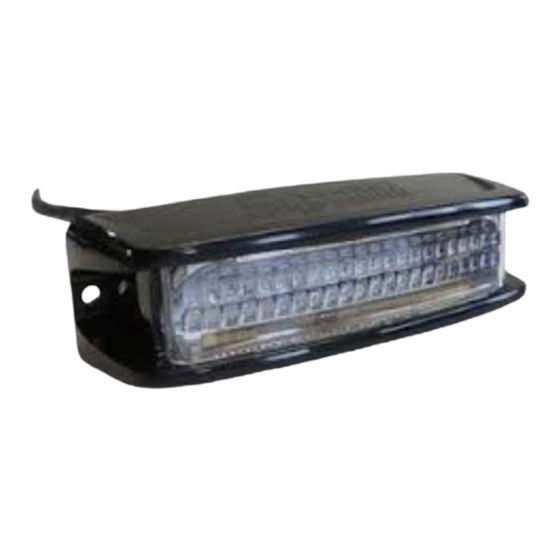
SURFACE MOUNTS
ENFSSS(xx) - SINGLE
ENFDSS(x)(xx) - DUAL
WARNING
• HIGH CURRENT interconnects must be properly terminated. Poor crimp
quality can cause heat build-up and fire. Follow the crimp connector
manufacturer instructions.
• DO NOT install this product or route any wires in the Air Bag Deployment
Zone. Refer to vehicle Owner's Manual for deployment zones.
• Do NOT use system to disconnect headlights, brake lights or other safety
equipment.
• Unit may become hot to touch during normal operation.
• Failure to properly install connectors, fuses or wiring may cause vehicle
failure or fire.
• Installation must only be performed by trained technician. Installer must
determine vehicle wiring configuration and proper integration of system.
• Use proper wire gauge. All power wires connecting to positive (+) or
negative (-) battery terminal or local chassis ground (-) must be sized to
supply at least 125% of max. current and properly fused at power source.
• Install protective grommets when routing wire through firewall or metal.
• Petroleum/silicone based lubricants will cause the silicone lens to discolor.
1.800.338.7337 / www.soundoffsignal.com
NOTICE:
Installers and users must comply with all applicable federal, state and local laws regarding use and installation of warning
devices. Improper use or installation may void warranty coverage. To review our Limited Warranty Statement & Return Policy
for this or any SoundOff Signal product, visit our website at www.soundoffsignal.com/tech-services/returns/. If you have
questions regarding this product, contact Technical Services, Monday - Friday, 8 a.m. to 5 p.m. ET at 1.800.338.7337 (press
#4). Questions or comments that do not require immediate attention may be emailed to techservices@soundoffsignal.com.
E N H A N C I N G S A F E T Y T H R O U G H I N N O VAT I O N
DIMENSIONS / TECHNICAL SPECIFICATIONS . . . . . . 2
SURFACE MOUNT INSTALL . . . . . . . . . . . . . . 3
SINGLE AND DUAL MOUNTING TEMPLATES . . . . 3
ELECTRICAL INSTALLATION / INFORMATION . . . 4 - 7
WARRANTY INFORMATION . . . . . . . . . . . . . . . . . . 8
WARNING
!
ROUTE WIRES ONLY IN LOCATIONS THAT ARE NOT SUBJECTED TO
POTENTIAL WEAR. MAKE SURE TO AVOID ROUTING WIRES IN THE
DEPLOYMENT AREA OF YOUR AIR BAG. REFER TO YOUR VEHICLE'S
OWNER'S MANUAL FOR AIRBAG DEPLOYMENT ZONES.
Scan for the latest version
of the instruction sheet
NFORCE SURFACE MOUNT ENF(X)SS(XXX)
ENGLISH 0000JL 1023 REV A
Advertisement
Table of Contents

Related Manuals for Soundoff Signal nFORCE ENFSSS Series


Summary of Contents for Soundoff Signal nFORCE ENFSSS Series
- Page 1 Improper use or installation may void warranty coverage. To review our Limited Warranty Statement & Return Policy for this or any SoundOff Signal product, visit our website at www.soundoffsignal.com/tech-services/returns/. If you have questions regarding this product, contact Technical Services, Monday - Friday, 8 a.m. to 5 p.m. ET at 1.800.338.7337 (press #4).
-
Page 2: Operation
NFORCE DECK/GRILLE LED LIGHT DECK / GRILLE DIMENSIONS / SPECIFICATIONS: OPERATION: For details on operation see page with ‘Flash Patterns’ table on page 4. TECHNICAL SPECIFICATIONS Single Mount Dimensions: 5.0” (127 mm) L x 1.72” (44 mm) H x 1.50” (38 mm) D 5.0”... -
Page 3: Surface Mount Installation
NFORCE DECK/GRILLE LED LIGHT SURFACE MOUNT INSTALLATION: Deck / Grille Bracket (FIG. 1) FIG. 1 FIG. 1 1. Establish a position on the vehicle. Use the gasket (provided) as a template to drill 1/4” diameter wire hole and pilot holes for mounting screws. -
Page 4: Electrical Instructions
NFORCE DECK/GRILLE LED LIGHT ELECTRICAL INSTRUCTIONS: ADVANCE PATTERN When the light is flashing, momentarily touch the white or yellow wire to ground for >3s and <4s (light will go steady Flash pattern can only be changed when the LED module is high, steady low, off, steady high) then release. - Page 5 NFORCE DECK/GRILLE LED LIGHT ELECTRICAL INSTRUCTIONS CONTINUED: FUNCTION TABLES Changing the function table is only enabled when the LED When the light is flashing, momentarily connect the White or Yellow wire to ground for >4S and <5S (light will go module is in a flashing mode (disabled in cruise or steady steady high, steady low, off, steady high, steady low) then ON functions).
- Page 6 NFORCE DECK/GRILLE LED LIGHT ELECTRICAL INSTRUCTIONS CONTINUED: SYNC 2 Synchronizing the flashing of multiple light modules is Refer to the Sequence Type section in Set-Up table to accomplished by connecting the Green or Blue wires of setup light modules to flash in alternate or simultaneous different light modules together.
- Page 7 NFORCE DECK/GRILLE LED LIGHT ELECTRICAL INSTRUCTIONS CONTINUED: REMOTE MODE: FOR USE WITH bluePRINT SYSTEM ONLY Connecting the Green or Blue wire to ground before applying power to the Red(Orange) or Red/White(Orange/White) wires will place the LED module into remote mode and the light output color will be directly controlled by the input wires as shown below.
- Page 8 Hudsonville, MI 49426 WARRANTY EXCLUSIONS: Shipping & Handling, labor and service fees are non-refundable. SoundOff Signal is not liable for any damage due to installation or personal injury as a result of using SoundOff Signal product. WARRANTY FORFEITURE: Warranty will not be granted if the Warranty Return Policy &...
Need help?
Do you have a question about the nFORCE ENFSSS Series and is the answer not in the manual?
Questions and answers