Table of Contents
Advertisement
Quick Links
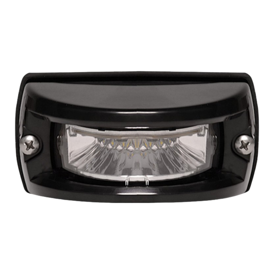
INTERSECTOR™
LED LIGHT
#ENT3(y)3(x) - SURFACE MOUNT
#PNT3DGBB DECK/ GRILLE BRACKET, BLACK
SURFACE MOUNT
Please see last page for
Important Information:
• Warning devices are strictly regulated and governed by Federal, State and Municipal ordinances.
These devices shall be used ONLY on approved vehicles. It is the sole responsibility of the user of these
devices to ensure compliance.
• DO NOT install this product or route any wires in the Air Bag Deployment Zone. Refer to your vehicle
Owner's Manual for the location of any air bag deployment zones.
• DO NOT connect this device to a strobe power supply. This product is self-contained and does not
require an external power supply.
BRACKET
GASKET
BEZEL
HOUSING
8/32 x 1" PHIL PAN SCREWS
DECK/ GRILLE BRACKET MOUNT
SURFACE MOUNT
INSTALLATION:
1. Establish a position on the vehicle on a level
surface. Orient the light output level on the
horizon.
2. Use the gasket provided as a template to
mark locations of wire and mounting
screws
3. Use a 5/8" diameter drill for the wire holes
4. Size pilot holes for mounting screws
appropiately.
5. Fasten light using bezel and mounting
screws. Do not torque mounting screws
beyond 20 in - lbs.
DECK/ GRILLE BRACKET
INSTALLATION:
(PURCHASED SEPARATELY)
1. Slide wire from Bezel through center
access hole in the gasket and bracket.
2. Next, position the Housing over the Bezel
and align the holes with the bracket.
3. Lastly, using the supplied 8-32 x 1"
screws fasten the assembly lightly. Do
not torque mounting screws beyond 20
in - lbs.
4. Establish a position on the vehicle on a level
surface. Orient the light output level on the
horizon.
5. Use the bracket provided as a template to
mark locations of mounting screws.
6. Size pilot holes for mounting screws
appropiately.
7. Fasten light using bezel and mounting
screws. Do not torque mounting screws
beyond 20 in - lbs.
OPERATION:
For details on operation see page with 'Flash
Patterns' table on last page.
IMPORTANT:
ALL WIRES 22ga
Power should only be
supplied through RED
WIRE of flasher harness
and must be fused with
MALE
a 3A, user supplied,
CONNECTOR
in-line fuse. Failure to
FROM FLASHER
1
2
3
4
install this fuse will create
a fire hazard and will
damage the Intersector™
Light. Connecting the
Intersector™ light to any
FEMALE
power source directly
CONNECTOR
WILL permanently
1
2
3
4
damage the light and will
void warranty.
IMPORTANT! FOR
PROPER OPERATION
ALL WIRES MUST BE
CONNECTED FROM
FLASHER TO LIGHT
HEAD.
INTERSECTOR
LIGHT
WIRE COLOR:
CONNECT TO:
(ALL WIRES 20ga)
(FROM FLASHER ONLY)
RED
+10-16 Vdc
WHITE Pattern Select / Sync
BLACK
Ground (-)
Cruise Mode
GREEN
(+10-16 Vdc)
WARNING
!
This product contains high intensity LED devices. To
prevent eye damage, DO NOT stare into the light
beam at close range.
Advertisement
Table of Contents

Subscribe to Our Youtube Channel
Related Manuals for Soundoff Signal Intersector ENT3 3 Series


Summary of Contents for Soundoff Signal Intersector ENT3 3 Series
-
Page 1: Important Information
OPERATION: SURFACE MOUNT For details on operation see page with ‘Flash INSTALLATION: Patterns’ table on last page. 1. Establish a position on the vehicle on a level surface. Orient the light output level on the IMPORTANT: ALL WIRES 22ga INTERSECTOR™ LED LIGHT horizon. - Page 2 SINGLE LIGHT HEAD SET UP AND PATTERN SELECTION Flash Patterns 1. Disconnect WHITE wire from any connections if applicable. F.P.M. 2. Turn Intersector™ LED LIGHT ON by applying power to RED WIRE Alternating Simultaneous (Flashes / Pattern Name 1 Light 2 Lights 2 Lights Minute)
- Page 3 OPERATION: SURFACE MOUNT For details on operation see page with ‘Flash Patterns’ table on page 4. INSTALLATION: IMPORTANT: 1. Establish a position on the vehicle on a level Supply power through a 3A fuse. For surface. Orient the light output level on the Flashing mode, refer to function tables 1,2 INTERSECTOR LED LIGHT horizon.
- Page 4 INTERSECTOR LED LIGHT #ENT3(y)3(x) - SURFACE MOUNT #PNT3DGBB DECK/ GRILLE BRACKET, BLACK ADVANCE PATTERN Flash pattern can only be changed when the LED module is in a flashing mode (disabled in cruise or steady ON functions). When the light is flashing, momentarily touch the white wire to ground for >250ms and <1s (light will go steady high) then release.
- Page 5 INTERSECTOR LED LIGHT #ENT3(y)3(x) - SURFACE MOUNT #PNT3DGBB DECK/ GRILLE BRACKET, BLACK FUNCTION TABLES Changing the function table is only enabled when the LED module is in a flashing mode (disabled in cruise or steady ON functions). The functional operation of the LED module can be changed while applying +vdc to the Red wire with the black wire connected to ground.
- Page 6 INTERSECTOR LED LIGHT #ENT3(y)3(x) - SURFACE MOUNT #PNT3DGBB DECK/ GRILLE BRACKET, BLACK SYNC 2 Syncronizing the flashing of multiple light modules is accomplished by connecting the Green wires of different light modules together. Up to 24 light modules can be connected for syncronized flashing. All light module flash patterns must be set to the same flash pattern # to ensure proper operation.
- Page 7 INTERSECTOR LED LIGHT #ENT3(y)3(x) - SURFACE MOUNT #PNT3DGBB DECK/ GRILLE BRACKET, BLACK REMOTE MODE: FOR USE WITH bluePRINT SYSTEM ONLY Connecting the Green wire to ground before applying power to the Red or Red/White wires will place the LED module into remote mode and the light output color will be directly controlled by the input wires as shown below.
- Page 8 INTERSECTOR LED LIGHT #ENT3(y)3(x) - SURFACE MOUNT #PNT3DGBB DECK/ GRILLE BRACKET, BLACK OVER-VOLTAGE PROTECTION When an over-voltage condition is detected, the module will flash an over-voltage warning pattern of 50mS ON/950mS OFF to alert of the over-voltage condition and protect the electronics from damage due to heat/ voltage.
Need help?
Do you have a question about the Intersector ENT3 3 Series and is the answer not in the manual?
Questions and answers