Lowenstein Medical LUISA Instructions Manual
Ventilators
Hide thumbs
Also See for LUISA:
- Instructions for use manual (40 pages) ,
- Instructions for use manual (40 pages) ,
- Support manual (4 pages)

Related Manuals for Lowenstein Medical LUISA


Summary of Contents for Lowenstein Medical LUISA
- Page 1 US Instructions for Use for devices of type LM150TD Device Firmware Version 1.3 LUISA Ventilators...
-
Page 2: Table Of Contents
11.4 Electromagnetic interference immunity ..47 5.5 Configuring and enabling ventilation 11.5 Markings and symbols ........48 programs ............18 11.6 Scope of delivery for LMT 31390US-1110 LUISA Hygiene treatment and servicing with HFT mode ..........48 11.7 Accessories ............ 49 6.1 Hygiene treatment ......... -
Page 3: Introduction
In addition, a maximum of two external batteries invasive and non-invasive ventilation. can be connected to operate the device. Caution : The LUISA device is not intended for use as an Therapy data is stored in the device and can additionally be emergency transport ventilator. -
Page 4: Side Effects
2 Safety 1.5 Side effects blockages, replace the breathing system filter more frequently. Set up external humidifiers below the device and the When using the device, the following undesired side effects patient connection. Water in the device may damage may occur in the short-term or long-term use: Pressure the device or injure the patient. -
Page 5: General Information
Operating the device in any kind of carrying bag may impair device performance and injure the patient. Water and dirt in the device may damage the device. Only operate the device in the associated LUISA mobility bag. Transport or store the device in the associated LUISA protective bag. -
Page 6: Product Description
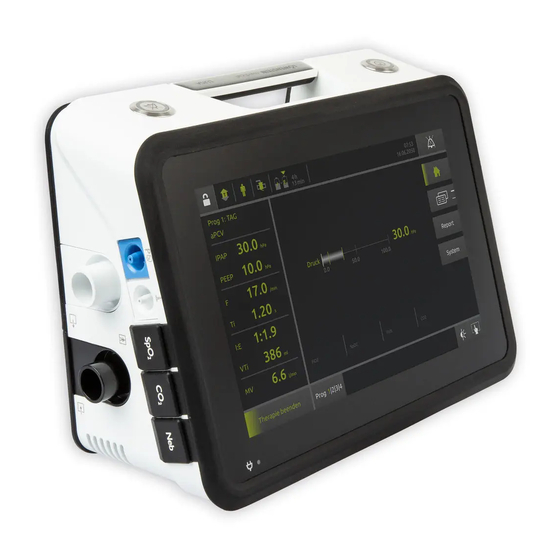
3 Product description 3 Product description 3.1 Overview 2 3 4 10 11 External battery connection Filter compartment with coarse dust filter and fine filter Connection for monitor/prisma HUB Compartment for internal battery USB-C connection Exhalation circuit connection Nurse call system connection Device outlet port Power supply indicator Handle... -
Page 7: Control Panel In Display
3 Product description 3.2 Control panel in display Status line - symbols indicate current device status (e.g. accessories connected, battery capacity). Alarm acknowledgement key - Press briefly: Acknowledges alarm. If the alarm persists, the alarm is muted for 2 minutes. Press and hold: Mutes all acoustic alarms for 2 minutes. -
Page 8: Symbols In Display
Battery fault Protective bag for Serves to transport and store the LUISA device with protection Filter change (only if function is activated). Follow the instructions for use for the accessories. Service reminder function (only if function is Here you will find further information about activated). -
Page 9: Batteries
3 Product description 3.6 Batteries Remaining life is a prediction and always relates to the current mean consumption of the device. Following the start of ventilation, no more than 3 minutes 3.6.1 Internal battery will elapse before remaining life is displayed. •... -
Page 10: Data Management/Compatibility
3 Product description 3.8 Data management/ compatibility Anyone who integrates medical devices or medical software products in an IT network or installs them on a PC or integrates devices or software products in a medical IT network or installs them on a PC is responsible for complying with IEC 80001-1. -
Page 11: Preparation And Operation
4 Preparation and operation 4 Preparation and operation 4.1 Setting up and connecting device Risk of injury from inadequate therapy if air inlet and air outlet are blocked! A blocked air inlet and/or air outlet can cause the device to overheat, impair therapy and damage the device. - Page 12 4 Preparation and operation 4.2.1 Connecting leakage circuit 4.2.3 Connecting double circuit 1. Push the free end of the circuit 1 onto the device outlet 1. Push the circuit onto the device outlet port. port. 2. Connect the invasive or non-invasive patient/ventilator 2.
-
Page 13: Before First Use
4 Preparation and operation 4.2.5 Connecting the circuit for HFT The device automatically performs a few function tests. The alarm system is tested automatically. If the device is mode fully functional, the start screen is displayed and the device switches to standby. 4.5 Starting therapy Requirement •... -
Page 14: Performing Circuit Test
4 Preparation and operation 4.7 Performing circuit test Perform a circuit test at every function check, on change of patient and as required. This checks for resistance, compliance and leaks. Requirement Type of circuit used is selected in the Ventilation menu. 1. -
Page 15: Settings In The Menu
5 Settings in the menu 5 Settings in the menu 5.1 Navigating in the menu ACTION FUNCTION ACTION FUNCTION Opens range of values for setting Function keys have a gray Press “Value” ventilation parameters background and the function is displayed on the key in text or as a Move range of values Decrease or increase value symbol (e.g. -
Page 16: Expert Menu
5 Settings in the menu 5.2.3 System menu in the Patient menu PARAMETER DESCRIPTION Lists the alarms which have occurred. Perform a circuit test here on change The log is retained when the alarm of patient and as required. This checks system or the device is switched off. -
Page 17: Expert Menu Structure
5 Settings in the menu 5.4 Expert menu structure Ventilation programs (Patient type) Various alarms Alarms (Circuit) (Circuit) Graph view Ventilation (vary depending on configuration) (Views) Ventilation mode Remaining life/charging status Various ventilation parameters Program settings (vary depending on configuration) Circuit test Alarm volume FiO2 cell... -
Page 18: Configuring And Enabling Ventilation Programs
5 Settings in the menu PARAMETER DESCRIPTION PARAMETER DESCRIPTION Lists the alarms and events which have You can activate the reminder function Alarm/event list occurred in chronological order. for the next service here. Select the Service timer period for the next service. Once the Lists all parameters and set values for service has been performed, you can Parameter overview... -
Page 19: Hygiene Treatment And Servicing
6 Hygiene treatment and servicing 6 Hygiene treatment and servicing 6.1 Hygiene treatment • LMT 31487 Coarse dust filter • LMT 31422 Filter holder 6.1.2 Cleaning intervals INTERVAL ACTION Risk of infection when the device is used again! If the device is used by several patients, infections may be Clean device (see “6.1.3 Subjecting device Weekly... - Page 20 6 Hygiene treatment and servicing Cleaning coarse dust filter (gray filter) 1. To open the exhalation module compartment on the rear of the device, turn the latch counterclockwise to the symbol. 2. Remove cover. 3. Remove exhalation module. 1. Open filter compartment flap. 2.
-
Page 21: Function Check
6 Hygiene treatment and servicing 3. Wash filter under running water. 8. Seal the end of the circuit and start ventilation. A brief acoustic alarm must be audible on starting. The device 4. Allow filter to dry. automatically performs a few function tests. 5. - Page 22 6 Hygiene treatment and servicing ALARM ID NO. REQUIREMENT TEST Connect test lung. Start ventilation. Single circuit with valve is connected. On a single circuit with valve: Seal exhalation opening Exhalation blocked Alternatively of patient valve. (Obstruction) Double circuit is connected. On a double circuit: Take the circuit off the device and seal the connection.
-
Page 23: Servicing
6 Hygiene treatment and servicing ALARM ID NO. REQUIREMENT TEST Volume controlled Start ventilation with a sealed circuit at the patient Tidal volume permanently mode or pressure connection. controlled mode with Wait 15 breaths. target volume set Start ventilation. Double circuit Exhalation blocked Seal off circuit. -
Page 24: Ventilation Modes
7 Ventilation modes 7 Ventilation modes 7.1 CPAP mode During therapy in CPAP mode, the device continuously The graph shows the currently regulated airway pressure supplies the patient with respiratory air at a constant positive over time. pressure. 7.1.1 Adjustable parameters in CPAP mode PARAMETER ADJUSTABLE VALUES DESCRIPTION... -
Page 25: St Mode
7 Ventilation modes PARAMETER ADJUSTABLE VALUES DESCRIPTION Trigger Set trigger sensitivity here. sensitivity on 1: Highly sensitive 1 – 10 Auto inspiration 10: Not very sensitive Auto: Device optimizes trigger sensitivity. Set trigger sensitivity on exhalation here. Triggering is effected Trigger when the following values are reached by maximum flow on sensitivity on... -
Page 26: T Mode
7 Ventilation modes PARAMETER ADJUSTABLE VALUES DESCRIPTION Trigger lockout time on 0.2 s – 5 s Trigger signals on inspiration are ignored during the set period. inspiration Speed of modification: On: 100 ml – 3,000 ml • Level 1: 0.5 cmH O every 8 breaths IPAP max: 4 cmH O to 60... -
Page 27: Psv Mode
7 Ventilation modes The graph shows the currently regulated airway pressure over time. 7.6.1 Adjustable parameters in TTV-VAPS-AE mode PARAMETER ADJUSTABLE VALUES DESCRIPTION EPAP min 4 – 20 cmH Set minimum EPAP here. EPAP max 4 – 20 cmH Set maximum EPAP here. Set the pressure difference between IPAP and EPAP here: Pinsp. -
Page 28: Apcv Mode
7 Ventilation modes 7.7.1 Adjustable values in PSV mode PARAMETER ADJUSTABLE VALUES DESCRIPTION 4 – 50 cmH O(leakage circuit) IPAP 4 – 60 cmH O (single or double circuit Set positive airway pressure on inspiration here. with valve) 4 – 25 cmH O (leakage circuit) PEEP 0 –... -
Page 29: Pcv Mode
7 Ventilation modes 7.8.1 Adjustable parameters in aPCV mode PARAMETER ADJUSTABLE VALUES DESCRIPTION 4 – 50 cmH O (leakage circuit) IPAP 4 – 60 cmH O (single or double circuit Set positive airway pressure on inspiration here. with valve) 4 – 25 cmH O (leakage circuit) PEEP 0 –... -
Page 30: Vcv Mode
7 Ventilation modes The graph shows the currently regulated airway pressure over time. 7.10.1 Adjustable parameters in aVCV mode PARAMETER ADJUSTABLE VALUES DESCRIPTION Volume 100 ml – 3,000 ml Set the volume delivered (V ) here. Set positive airway pressure PEEP 0 –... -
Page 31: V-Simv Mode
7 Ventilation modes 7.12.1 Adjustable parameters in P-SIMV mode PARAMETER ADJUSTABLE VALUES DESCRIPTION 4 – 50 cmH O (leakage circuit) 4 – 60 cmH O (single or double Set pressure support during spontaneous breaths here. circuit with valve) 4 – 50 cmH O (leakage circuit) IPAP 4 –... -
Page 32: Mpvp Mode
7 Ventilation modes PARAMETER ADJUSTABLE VALUES DESCRIPTION Set trigger sensitivity here: Trigger 1: Highly sensitive 1 – 10 sensitivity on Auto 10: Not very sensitive inspiration Auto: Device optimizes trigger sensitivity. Set trigger sensitivity on exhalation here. Triggering is effected when Trigger the following values are reached by maximum flow: sensitivity on... -
Page 33: Overview Of Available Ventilation Modes In The Circuits
7 Ventilation modes 7.15.1 Adjustable parameters in MPVv mode PARAMETER ADJUSTABLE VALUES DESCRIPTION Volume 100 ml – 3,000 ml Set the volume delivered (V ) here. 4 – 50 cmH O (leakage circuit) IPAP 4 – 60 cmH O (single or double Set positive airway pressure on inspiration here. -
Page 34: Alarms
8 Alarms 8 Alarms 8.3 Configuring physiological A distinction is made between two types of alarm: Physiological alarms relate to ventilation of the patient. alarms Technical alarms relate to configuration of the device. The technical alarms are active and cannot be configured. All physiological alarms are deactivated on delivery or when 8.1 Sequence in which alarms the device is reset to factory settings. - Page 35 8 Alarms DISPLAY CODE CAUSE ACTION Minute volume high Maximum minute volume exceeded. Check therapy and alarm settings. Minute volume low Minimum minute volume undershot. Check therapy and alarm settings. Ventilation parameter settings not suitable (upper alarm setting for patient Pulse high Check therapy and alarm settings.
-
Page 36: Technical Alarms
8 Alarms 8.4 Technical alarms DISPLAY CODE CAUSE ACTION Service necessary. Please Technical fault which can only be get in touch with your Various eliminated by an authorized specialist Have device repaired. specialist dealer/contact. dealer. Intake air temperature Operate device at an ambient temperature of high Ambient temperature too high. - Page 37 8 Alarms DISPLAY CODE CAUSE ACTION Internal battery Battery has switched off due to temperature. overheated Internal battery overheated. Operate device at an ambient temperature of 5 °C to 40 °C. Unable to charge Contact your specialist dealer. Have battery internal battery Internal battery defective.
- Page 38 8 Alarms DISPLAY CODE CAUSE ACTION Error battery E1 External battery 1 defective. communication Contact your specialist dealer. Device defective. Error battery E2 External battery 2 defective. communication Contact your specialist dealer. Device defective. Error battery E1 External battery 1 defective. Contact your specialist dealer.
- Page 39 8 Alarms DISPLAY CODE CAUSE ACTION No FiO cell Contact your specialist dealer. Have FiO cell No FiO cell fitted. fitted. cell empty Contact your specialist dealer. Have FiO cell cell empty. replaced. Blower temperature Cool device immediately or therapy will end. Blower temperature too high.
-
Page 40: Nurse Call And Remote Alarm
9 Faults DISPLAY CODE CAUSE ACTION Device operated with open patient/ Disconnection patient ventilator interface (mask not applied). Check circuit, connections, and patient/ ventilator interface at the patient. Circuit is not connected to the device correctly or is not connected at all. 8.5 Nurse call and remote alarm For support in monitoring patient and device, especially in In a domestic environment, you can connect the device to... -
Page 41: Technical Specifications
10 Technical specifications 10 Technical specifications SPECIFICATION DEVICE Product class to 93/42/EEC Dimensions W x H x D in cm 30 x 13 x 21 Weight 3.8 kg Temperature range - Operation +5 °C to +40 °C - Transport and storage -25 °C to +70 °C - Transport and storage at +70 °C Allow to cool to room temperature for 4 hours before starting... - Page 42 10 Technical specifications SPECIFICATION DEVICE Internal/external battery Type Li-ion Nominal capacity 3200 mAh Nominal voltage 29.3 V Energy 93.7 Wh Typical discharge cycles 500 charging cycles Battery capacity is reduced when the device is operated at low temperatures. Operating hours of internal battery assuming following settings: Double circuit, PCV mode, f=20/min, Ti=1 s, PEEP=off, Vt=800 ml ≥...
- Page 43 10 Technical specifications SPECIFICATION DEVICE EPAP pressure range 4 cmH O - 25 cmH Most disadvantageous circuit for leakage ventilation: Circuit WM 29988, bacteria filter WM 27591 0 cmH O - 25 cmH PEEP pressure range Most disadvantageous circuit for valve ventilation: Circuit LMT 31383, bacteria filter WM 27591 ±(2 cmH O + 4 % of the set value)
- Page 44 10 Technical specifications SPECIFICATION DEVICE Fine filter Filter class E10 up to 1 µm ≥ 99.5 % ≥ 85 % up to 0.3 µm Service life of fine filter approx. 250 h USB flash drive USB-C 3.0 Materials Fire-retardant technical thermoplastics and silicones, stainless Housing steel Fine filter...
-
Page 45: Annex
11 Annex 11 Annex 11.1 Pneumatic diagram 11.1.1 Leakage circuit Leakage Circuit O2 pathway O2 supply Patient Interface inspiration Pressure sensor for patient pressure exhalation Spontaneous ambient air Optional Optional: Optional: breathing & Air filter Blower Flow sensor Patient circuit Leakage system O2- sensor bacteria filter... -
Page 46: System Resistances
ARTICLE NAME NUMBER IN L/MIN CMH2O LMT 31382 LUISA, single circuit with valve, 180 cm, 22 mm Ø 0.11 LMT 31383 LUISA, single circuit with valve, 150 cm, 15 mm Ø 0.46 LUISA, single circuit with valve, heated (i), autofill LMT 31384 2.04... -
Page 47: Emission Of Electromagnetic Interference
PRESSURE DROP IN ARTICLE NAME NUMBER IN L/MIN CMH2O Inspiration circuit: 2.03 LUISA, double circuit, heated (i+e), A-shaped adapter, Inspiration circuit from LMT 31582 autofill chamber, 150 cm + 60 cm, 15 mm Ø patient to device: 2.05 Exhalation circuit: 2.06 Inspiration circuit: 0.22... -
Page 48: Markings And Symbols
TYPE: Type designation of the device 11.6 Scope of delivery for LMT Order number 31390US-1110 LUISA with HFT mode Suitable for use in aircraft. Meets RTCA/DO- 160G Section 21, Category M. The parts below are included in the standard scope of... -
Page 49: Accessories
VENTIremote alarm, 30 m LMT 31570 cigar or other smoke; (j) environmental conditions (including Cable, 10 m, nurse call for LUISA LMT 31510 but not limited to water, flame, chemicals, fumes in the Cable, 30 m, nurse call for LUISA... - Page 50 11 Annex WHAT IS THE PERIOD OF COVERAGE? THE REMEDIES DESCRIBED ABOVE ARE YOUR SOLE AND EXCLUSIVE REMEDIES AND LOEWENSTEIN MEDICAL’S This Limited Warranty lasts for the corresponding Warranty ENTIRE LIABILITY FOR ANY BREACH OF THIS LIMITED Period indicated in the table above from the date of WARRANTY.
- Page 52 Manufactured for: Loewenstein Medical Americas Corp. 3340 Peachtree Rd, Suite 1800 Atlanta, GA, 30326 United States of America...
Need help?
Do you have a question about the LUISA and is the answer not in the manual?
Questions and answers