Lowenstein Medical LUISA LM150TD Instructions For Use For Patients
Ventilator for home environment
Hide thumbs
Also See for LUISA LM150TD:
- Instructions for use manual (104 pages) ,
- Instructions for use manual (40 pages) ,
- Instructions for use manual (40 pages)

Subscribe to Our Youtube Channel
Related Manuals for Lowenstein Medical LUISA LM150TD


Summary of Contents for Lowenstein Medical LUISA LM150TD
- Page 1 EN-US Instructions for use for patients For devices of type: LM150TD LUISA Ventilator for home environment...
-
Page 2: Table Of Contents
Contents Contents 1 Introduction set alarms ............22 Intended use ..........Physiological alarms ........22 Description of function........ Technical alarms........... 24 User qualification ......... Nurse call and remote alarm ...... 26 Indications ............ 8 Troubleshooting Contraindications......... 9 Technical data Side effects............ Ambient conditions ........ -
Page 3: Introduction
1 Introduction 1 Introduction Intended use Blower output is controlled on the basis of the signals detected by the pressure and flow sensors and is thus The LM150TD ventilator is for life-support and non- adapted to suit therapy pressure. life-support ventilation of patients who require me- An external SpO sensor can be connected to measure chanical ventilation. -
Page 4: Indications
1 Introduction Person Description User qualification Specialist dealer Person or organization that markets, but Following training by the manufacturer in does not itself manufacture a product. The how the device works and how to use it, specialist dealer can provide a support specialist dealers are regarded as specialist function. -
Page 5: Safety
2 Safety 2 Safety Safety information ⇒ If the device and battery have been stored outside the quoted operating temperature, the device may only be started up once it has warmed up or 2.1.1 Energy supply cooled down to the permitted operating tempera- Operating the device outside the specified energy ture (wait at least 4 hours). -
Page 6: Wireless Communication
2 Safety ⇒ The oxygen flow supplied (in l/min) must not ex- ⇒ Set up external humidifiers below the device and ceed the set HFT flow. below the patient connection port. Water in the de- vice may damage the device or injure the patient. 2.1.7 Wireless communication 2.1.10 Transport and mobile use The device contains components for wireless commu-... -
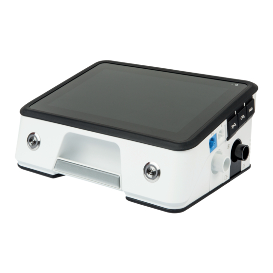
Page 7: Product Description
3 Product description 3 Product description Overview 2 3 4 7 8 9 10 11 Connection for external batteries Patient air intake area Connection for monitor Compartment for internal battery Connection for USB-C Intake area for cooling fan Remote alarm connection Device inlet port Power supply indicator Device outlet port... -
Page 8: Display
3 Product description Display Status line - symbols indicate current device status (e.g. Dimmer key - the display goes dark. Touch the display accessories connected, battery capacity). to activate it. Keep key depressed to open the display menu. Alarm acknowledgement key - acknowledges alarms Program key - provides access to the therapy pro- and mutes alarms. -
Page 9: Operating States
3 Product description • The on/off key is illuminated. Symbol Description After 10 minutes without operation, the display goes Filter change (only if function is activated) dark. If the device is in battery mode and is not operated Service reminder (only if function is activated) for 40 minutes, it will switch off to save energy. -
Page 10: Data Management/Compatibility
3 Product description Data management/compatibil- Trolley 2.0 The health institution is responsible for applying risk management to medical IT networks in ac- cordance with IEC 80001-1. Medical IT networks are IT networks which incorporate at least one medical device. The manufacturer does not accept any warranty or liability for interactions between system com- ponents within a medical IT network. -
Page 11: Preparation And Operation
4 Preparation and operation 4 Preparation and operation Setting up and connecting de- Connect circuit vice CAUTION Risk of injury from incorrectly routed circuits CAUTION and cables! Risk of injury from overheated device! ⇒ Do not route circuits and cables along the pa- Excessive temperatures may overheat the de- tient’s neck. -
Page 12: Before First Use
4 Preparation and operation 4.2.3 Connecting single circuit with valve 1. Push the free end of the leakage circuit onto the device outlet. It is likewise possible to use a single WARNING circuit with valve or a double circuit. Risk of injury from limited disconnection de- 2. -
Page 13: Switch Device On And Off / Start And End Therapy
4 Preparation and operation Switch device on and off / Start and end therapy Action Requirement Operating state achieved Switch on device Device is connected (See On, therapy not in progress Briefly press on/off key Setting up and connecting on the device. device [} 11]). -
Page 14: Calibrating The Fio Cell
4 Preparation and operation 1. Activate the Bluetooth function in the System > De- vice settings > Connectivity menu. 2. In the Device list menu, select the Add new device entry. 3. Download the LUISA app onto a mobile terminal and follow the instructions in the LUISA app. -
Page 15: Transfer Data With Com Cable For Monitor
4 Preparation and operation in the display. If the USB modem is connected to pris- maCLOUD, there are only limited options for setting date and time on the device. If the USB modem does not connect automatically, your specialist dealer will have to set it first. Contact your specialist dealer. -
Page 16: Settings In The Menu
5 Settings in the menu 5 Settings in the menu Navigating in the menu Action Function Press function key Function keys have a gray background and the function is displayed on the key in text or as a symbol e.g., Start therapy. Symbols on a black background are not function keys, but serve to provide information about device status (See Symbols in the display... - Page 17 5 Settings in the menu 5.2.2 Report menu Alarm list Lists the alarms which have occurred. Event list Lists the events that have oc- curred. Alarm and event list Lists the alarms and events which have occurred in chronological order. Device usage Lists the usage time of the device and the duration of...
-
Page 18: Reprocessing And Maintenance
6 Reprocessing and maintenance 6 Reprocessing and maintenance 6.1.3 Reprocessing device Hygiene treatment WARNING WARNING Risk of injury from electric shock! Risk of infection when device and accessories Ingress of liquids may lead to a short-circuit, in- are reused! jure the user, and damage the device. Infections may be transmitted and the device ⇒... -
Page 19: Function Check
6 Reprocessing and maintenance 5. Allow filter to air-dry. Replace fine filter (white filter) 6. Insert filter. 7. Close exhalation module compartment. Function check Carry out a function check before using the device for the first time, after every hygiene treatment, and after every repair, but at least every 6 months. -
Page 20: Checking Alarms
6 Reprocessing and maintenance 2. Check whether the symbol in the status line is Calibrating FiO cell illuminated green. 1. If a FiO cell is in use: Calibrating FiO cell (See Cali- Do not use a function tester to assess the accuracy of brating FiO2 cell [} 14]). -
Page 21: Disposal
6 Reprocessing and maintenance Maintenance interval for batteries 4 years or 500 charge cycles Maintenance interval for mem- 4 years brane of nonreturn valve Maintenance interval for blower 35,000 h life Disposal Do not dispose of the product or any batteries in do- mestic waste. -
Page 22: Alarms
7 Alarms 7 Alarms General information 3. Set and confirm the desired value. In doing so, note the following conditions: The device uses acoustic and visual alarms to make • Set sensible alarm limits. you aware of an acute or imminent risk requiring your •... - Page 23 7 Alarms Display Code Cause Action Display Code Cause Action Minute Minute volume Check the therapy and Tidal vol- Maximum exha- Check the therapy and volume set not attained. alarm settings for ume on lation volume alarm settings for plausibility and suit- exp.
-
Page 24: Technical Alarms
7 Alarms Technical alarms Life of Service life of ex- Replace battery. battery ternal battery at Technical alarms relate to configuration of the device. E1/2 at an end. The technical alarms are active and cannot be config- an end ured. Battery External battery Battery has switched... - Page 25 7 Alarms Error cell defec- Contact your specialist No exha- No exhalation Connect exhalation FiO2 cell tive. dealer. lation system. system. Have FiO cell re- system Check circuit and pa- placed. tient interface are OK and fitted correctly. No FiO2 No FiO cell.
-
Page 26: Nurse Call And Remote Alarm
7 Alarms Blower Blower over- Therapy will end. over- heated. Allow device to cool heated down. Maxi- Resistance on in- Reduce resistance and mum de- spiration too restart device. vice pres- high. If the physiological sure ex- alarm persists, contact ceeded your specialist dealer. -
Page 27: Troubleshooting
8 Troubleshooting 8 Troubleshooting Fault Cause Action No running noise, nothing No power supply. Check the connection of the device to the power sup- in the display. ply. Check socket. Device does not reach set Coarse dust filter dirty. Clean coarse dust filter. If necessary: Replace filter. therapy pressure. -
Page 28: Physical Specifications And Classifications.
9 Technical data 9 Technical data Ambient conditions Temperature range, operation +5 °C to +40 °C Temperature range, storage -25 °C to +70 °C Humidity for operation, transport, and stor- Relative humidity 15% to 90%, no condensation > 35 °C to 70 °C at a water vapor pressure up to 50 hPa Air pressure range 700 hPa to 1100 hPa, corresponds to an altitude of 3000 m above... -
Page 29: Therapy
9 Technical data without battery charging, screen brightness 90% with the following settings: Mode: T, Patient: adult, leakage circuit 15 mm, IPAP: 40 hPa, EPAP: 4 hPa, F: 26.5 / min, Ti: 1.1s, pressure rise: level 1, pressure reduction: level 1, test lung, additional accessory: Breathing sys- tem filter, WilaSilent exhalation system Therapy All physiological flow and volume values are displayed... -
Page 30: Noise
9 Technical data Accuracy of the volume measured by the ventilator < ± (4 ml + 20% of current value), leakage circuit: ±(8 ml 50 ml + 20 % of current value) Accuracy of the volume measured by the ventilator ≥ ±... -
Page 31: Software
9 Technical data Typical discharge cycles Duration of complete battery charge < 6 hours Duration of 80 % battery charge < 5 hours Operating hours, internal battery ≥ 6 hours With the following settings: Double circuit, Mode: PCV, f: 20 min, Ti: 1 s, PEEP: Off, Vt: 800 ml, Passive lung: Resistance R= 5 hPa /(l/s);... -
Page 32: Annex
10 Annex 10 Annex 10.1 Pneumatic diagram 10.1.1 Single circuit with valve O₂ supply O₂ Ambient air Patient interface Inspiration Pressure sensor for valve control Pressure sensor for patient pressure Control valves for exhalation system Exhalation Coarse dust O₂ sensor Humidifier Spontaneou Blower... - Page 33 10 Annex 10.1.2 Double circuit O₂ supply Ambient air O₂ Ambient air Exhalation Exhalation Circuit Patient interface Flow sensor system Inspiration Pressure sensor for valve control Pressure sensor for Control valves for patient pressure exhalation system Coarse dust O₂ sensor Humidifier Spontaneou Breathing system...
-
Page 34: System Resistances
10 Annex 10.2 System resistances The total pneumatic resistance of the connected cir- Key performance characteristics to ISO cuit and of the connected accessories (e.g. humidifier, 80601-2-72 breathing system filter) between the device and the • Accuracy of airway pressure patient may not exceed the following value: •... -
Page 35: Markings And Symbols
10 Annex Interference immunity tests Compliance level Electrical fast transients (IEC 61000-4-4) ±2 kV for power cords ±1 kV for input and output cables Surge immunity (IEC 61000-4-5) ±1 kV line to line Conducted HF interference (IEC 61000-4-6) 3 Vrms 150 KHz to 80 MHz 6 Vrms in ISM and amateur radio bands between 150 kHz and... -
Page 36: Scope Of Supply
10 Annex 10.6 Scope of supply Part Article 31380- 31390- 10.6.1 Device without HFT mode 1110 1110 Protection bag LM150TD LMT 31417 The parts below are included in the standard scope of supply: USB-C flash drive LMT 31414 Patient record 1P-10088 Part Article... -
Page 37: Warranty
10 Annex 10.8 Warranty Part Article no. Set, hospital trolley consisting of:, consist- LMT 31370 Löwenstein Medical Technology gives the purchaser ing of: of a new original Löwenstein Medical Technology Trolley 2.0 (LMT 31355) product and of a spare part fitted by Löwenstein Med- Set, plate for trolley 2.0 ical Technology a limited manufacturer warranty in Set, device plate for device type LM150TD/... - Page 40 Manufacturer Löwenstein Medical Technology GmbH + Co.KG Kronsaalweg 40 22525 Hamburg, Germany T: +49 40 54702-0 F: +49 40 54702-461 www.loewensteinmedical.com 68691a...
Need help?
Do you have a question about the LUISA LM150TD and is the answer not in the manual?
Questions and answers