Lowenstein Medical LUISA Instructions For Use Manual
Ventilator for home environment
Hide thumbs
Also See for LUISA:
- Instructions for use manual (40 pages) ,
- Instructions manual (52 pages) ,
- Support manual (4 pages)

Related Manuals for Lowenstein Medical LUISA


Summary of Contents for Lowenstein Medical LUISA
- Page 1 EN-US Instructions for use for patients For devices of type: LM150TD LUISA Ventilator for home environment...
-
Page 2: Table Of Contents
Circuit test............. 13 Performing SpO measurement ....13 Calibrating the FiO cell....... 14 Pairing device with LUISA app....14 Contaminated components......14 5 Settings in the menu Navigating in the menu ......15 Menu structure ..........15 6 Reprocessing and maintenance Hygiene treatment........ -
Page 3: Introduction
1 Introduction 1 Introduction 1.1 Intended use Blower output is controlled and therapy pressure thus modified based on the signals detected by the pres- sure and flow sensors. The LM150TD ventilator is for the life-support and non-life-support ventilation of patients who require An external SpO sensor can be connected to measure mechanical ventilation. -
Page 4: Indications
1 Introduction 1.4 Indications Restoring proper ventilation/regulation of breathing either via permanent settings or via automatic reac- tions to the patient’s requirement, maintaining ade- Obstructive ventilation disorders (e.g. COPD), restric- quate gas exchange in the event of acute respiratory tive ventilation disorders (e.g. scolioses, deformities of failure, relieving the respiratory pump/supporting the the thorax), neurological, muscular, and neuromuscu- respiratory musculature, improving alveolar ventila-... -
Page 5: Safety
2 Safety 2 Safety 2.1 Safety information 2.1.3 Ambient conditions ⇒ Only operate, store and transport the device under the specified ambient conditions (See Ambient con- 2.1.1 Energy supply ditions [} 27]). Operating the device outside the specified energy ⇒ If device and battery have been stored outside the supply may cause personal injury, damage the device quoted operating temperature, the device can only or impair the performance of the device. -
Page 6: Safety Information In These Instructions For Use
2 Safety ⇒ Set up oxygen source at a distance of over 1 m apy pressure delivered. Replace breathing system from the device. filters more frequently to prevent increased resis- tance and blockages. ⇒ A healthcare professional specifies the oxygen dosage. The set oxygen flow must not exceed the ⇒... -
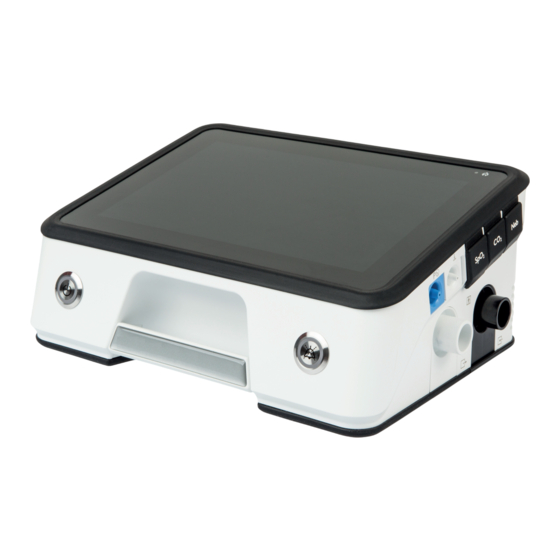
Page 7: Product Description
3 Product description 3 Product description 3.1 Overview 2 3 4 7 8 9 10 11 Connection for external batteries Connection for monitor Connection for USB-C Remote alarm connection Power supply indicator Alarm acknowledgement key Inlet port for pressure measuring tube Inlet port for valve control tube Inlet for SpO₂... -
Page 8: Display
3 Product description 3.2 Display Status line - symbols indicate current device status (e.g. Alarm acknowledgement key - acknowledges alarms accessories connected, battery capacity). and mutes alarms. Home key - switches the view back to the home display. 4 Menu buttons - provide access to the individual menus. Display lock key - locks or unlocks the display to pre- Dimmer key - the display goes dark. -
Page 9: Operating States
3 Product description Operating state “Off” Symbol Description Filter change (only if function is activated) The device is switched off. Therapy is not in progress. It is not possible to make device and therapy settings. The on/off key is not illuminated. Service reminder (only if function is activated) 3.5 Batteries Alarm triggered... -
Page 10: Data Management/Compatibility
3 Product description 3.6 Data management/com- 3.7 Trolley 2.0 patibility The health institution is responsible for applying risk management to medical IT networks in ac- cordance with IEC 80001-1. Medical IT networks are IT networks which incorporate at least one medical device. -
Page 11: Preparation And Operation
4 Preparation and operation 4 Preparation and operation 4.1 Setting up and connect- 4.2.1 Connecting leakage circuit 1. If the patient interface or circuit is used without an ing device integrated exhalation system, connect an external exhalation system (see instructions for use for ex- 1. -
Page 12: Before First Use
4 Preparation and operation 4.2.3 Connecting single circuit with 1. Push the free end of the leakage circuit onto the device outlet. It is likewise possible to use a single valve circuit with valve or a double circuit. WARNING 2. Connect mouthpiece to the tube (see instructions Risk of injury from limited disconnection detec- for use for the patient/ventilator interface). -
Page 13: Switch Device On And Off / Start And End Therapy
4 Preparation and operation 4.4 Switch device on and off / Start and end therapy Action Requirement Operating state achieved Switch on device Device is connected (See On, therapy not in progress Briefly press on/off key Setting up and connecting on the device. -
Page 14: Calibrating The Fio Cell
(expert). 4.8 Pairing device with LUISA app The LUISA app (option) is an app on a mobile terminal which you can use to read off the patient’s therapy data. -
Page 15: Settings In The Menu
5 Settings in the menu 5 Settings in the menu 5.1 Navigating in the menu Action Function Press function key Function keys have a gray background and the function is displayed on the key in text or as a symbol. Symbols on a black background are not function keys, but serve to provide information about device status (See Symbols in display... - Page 16 5 Settings in the menu View is only available in the patient menu if a display background has been selected in the device settings of the expert menu. 5.2.2 Report menu Alarm list Lists the alarms which have occurred. Event list Lists the events that have oc- curred.
-
Page 17: Reprocessing And Maintenance
6 Reprocessing and maintenance 6 Reprocessing and maintenance 6.1 Hygiene treatment WARNING Risk of injury from use of ozone! Ozone cleaning devices may damage the materi- WARNING als and thus put the patient at risk. Risk of infection if device and accessories are ⇒... -
Page 18: Function Check
6 Reprocessing and maintenance 4. Insert coarse dust filter. 2. Check connectors, cables, and accessories for ex- ternal damage. Consult associated instructions for 5. Close filter compartment. use. Clean filter for cooling air fan 3. Check that accessories are connected to the device correctly. -
Page 19: Servicing
6 Reprocessing and maintenance 6.2.1 Checking alarms Physiological alarms Alarm ID no. Requirement Test Leakage high On a single circuit with valve: Alarm Leave the inspiration tube on the pa- limit is set to a value < 150 l/min. tient connection port open. With leakage circuit: Alarm limit is set Start therapy. -
Page 20: Disposal
6 Reprocessing and maintenance 6.4 Disposal Do not dispose of the product or any batteries present with domestic waste. To dispose of properly, contact a licensed, certified electronic waste disposal merchant. This address is available from your Environ- ment Officer or from your local authority. The device packaging (cardboard and inserts) can be disposed of in paper recycling facilities. -
Page 21: Alarms
7 Alarms 7 Alarms 7.1 General information 3. Set and confirm the desired value. In doing so, note the following conditions: The device uses acoustic and visual alarms to make • Set sensible alarm limits. you aware of an acute or imminent risk requiring your •... - Page 22 7 Alarms Display Code Cause Action Display Code Cause Action Pulse Set pulse rate Check therapy and Minute Minimum expi- Check therapy and high exceeded. alarm settings for volume ratory minute alarm settings for plausibility and suit- on exp. volume under- plausibility and suit- ability for the patient.
-
Page 23: Technical Alarms
7 Alarms 7.5 Technical alarms Life of Service life of ex- Replace battery. battery ternal battery at E1/2 at an end. Technical alarms relate to configuration of the device. an end The technical alarms are active and cannot be config- ured. - Page 24 7 Alarms Error cell defec- Contact your specialist No exha- No exhalation Connect exhalation FiO2 cell tive. dealer. lation system. system. Have FiO cell re- system Check circuit and pa- placed. tient interface are OK and fitted correctly. No FiO2 No FiO cell.
-
Page 25: Nurse Call And Remote Alarm
7 Alarms Blower Blower over- Therapy will end. over- heated. Allow device to cool heated down. Maxi- Resistance on in- Reduce resistance and mum de- spiration too restart device. vice pres- high. If the physiological sure ex- alarm persists, contact ceeded your specialist dealer. -
Page 26: Troubleshooting
8 Troubleshooting 8 Troubleshooting Fault Cause Action No running noise, nothing in the No power supply. Check connection of device to display. power supply. Check socket. Device not reaching set therapy Coarse dust filter soiled. Clean coarse dust filter. If neces- pressure. -
Page 27: Technical Data
9 Technical data 9 Technical data 9.1 Ambient conditions Temperature range, operation +5 °C to +40 °C Temperature range, storage -25 °C to +70 °C Humidity for operation, transport, and storage Relative humidity 15 % to 90 %, no condensation > 35° C to 70°... -
Page 28: Therapy
9 Technical data Without battery charging, screen brightness 90 % With the following settings: Mode: T, Patient: Adult, leakage circuit 15 mm, IPAP: 40 hPa, EPAP: 4 hPa, F: 26.5/ min, Ti: 1.1 s, Pressure rise: Level 1, Pressure reduction: Level 1, Test lung, additional accessories: Breathing system filter, WilaSilent exhalation system Tolerance: -20 % + 10 % 9.5 Therapy... -
Page 29: Noise
9 Technical data Accuracy of the volume measured by the ventilator < ± (4 ml + 20% of current value), leakage circuit: ±(8 ml + 50 ml 20 % of current value) Accuracy of the volume measured by the ventilator ≥ ±... -
Page 30: Software
9 Technical data Energy 93.7 Wh Typical discharge cycles Duration of complete battery charge < 6 hours Duration of 80 % battery charge < 5 hours Operating hours, internal battery ≥ 6 hours With the following settings: Double circuit, Mode: PCV, f: 20 min, Ti: 1 s, PEEP: Off, Vt: 800 ml, Passive lung: Resistance R= 5 hPa /(l/s);... -
Page 31: Annex
10 Annex 10 Annex 10.1 Pneumatic diagram 10.1.1 Single circuit with valve O₂ supply O₂ Ambient air Patient interface Inspiration Pressure sensor for valve control Pressure sensor for patient pressure Control valves for exhalation system Exhalation Coarse dust O₂ sensor Humidifier Spontaneou Blower... - Page 32 10 Annex 10.1.2 Double circuit O₂ supply Ambient air O₂ Ambient air Exhalation Exhalation Circuit Patient interface Flow sensor system Inspiration Pressure sensor for valve control Pressure sensor for Control valves for patient pressure exhalation system Coarse dust O₂ sensor Humidifier Spontaneou Breathing system...
-
Page 33: System Resistances
10 Annex 10.2 System resistances The total pneumatic resistance of the connected cir- The pressure reduction values of the individual com- cuit and of the connected accessories (e.g. humidifier, ponents can be added to form a total resistance value breathing system filter) between the device and the which must not exceed the above value. -
Page 34: Markings And Symbols
10 Annex Interference immunity tests Compliance level High-frequency electromagnetic fields in the immedi- 9 to 28 V/m* ate vicinity of wireless communication equipment (IEC 385 MHz to 5.785 GHz* 61000-4-3) * Tested to IEC 60601-1-2:2020 Table 9 27 to 84 V/m* 385 MHz to 5.785 GHz* * Tested to IEC 60601-1-2:2020 Table 9 with test levels three times higher. -
Page 35: Scope Of Supply
10 Annex 10.6 Scope of supply Part Article 31380- 31390- 1110 1110 10.6.1 Device without HFT mode Protective bag LMT 31417 The parts below are included in the standard scope of USB-C flash drive LMT 31414 supply: Patient record 1P-10088 Part Article LM patient information... -
Page 36: Declaration Of Conformity
Disposable products None prismaTS / prismaTSlab software WM 93331 USB-C flash drive LMT 31414 COM cable for monitor LMT 31578 LUISA app FiO₂ cell, complete LMT 31502 Mobility bag, LM150TD LMT 31554 Exhalation module (disposable) LMT 31404 Exhalation module (autoclavable) - Page 40 Manufacturer Löwenstein Medical Technology GmbH + Co.KG Kronsaalweg 40 22525 Hamburg, Germany T: +49 40 54702-0 F: +49 40 54702-461 www.loewensteinmedical.com LMT 68691...
Need help?
Do you have a question about the LUISA and is the answer not in the manual?
Questions and answers