Table of Contents
Advertisement
Advertisement
Table of Contents

Related Manuals for Festo CMMP-AS


Summary of Contents for Festo CMMP-AS
- Page 1 Motor controller CMMP-AS Manual CAM editor GSPF-CAM-MC-ML Manual 752540 en 1105a...
- Page 2 Festo.P.BE-CMMP-CAM-SW-EN en 1105a...
- Page 3 Edition ____________________________________________________ en 1105a Designation ___________________________________ P.BE-CMMP-CAM-SW-EN Festo AG & Co KG., D-73726 Esslingen, Germany, 2011 Internet: http://www.festo.com E-mail: service_international@festo.com The reproduction, distribution and utilisation of this document as well as the communication of its contents to others without explicit authorisation is prohibited.
- Page 4 File name: 752540g1.pdf File saved at: Consec. no. Description Index of revisions Date of amendment Creation in German 1007NH 12.07.2010 Edit and translation 1105a 15.03.2011 Trademarks SIMATIC-S7 are registered trademarks of the respective trademark owners in certain countries. Festo.P.BE-CMMP-CAM-SW-EN en 1105a...
-
Page 5: Table Of Contents
Characteristics of the cam disc function ............. 18 Physical master ....................19 Virtual master ....................20 Master-slave constellations ................21 4.5.1 CMMP-AS as physical master with 3 slaves ......... 21 4.5.2 CMMP-AS as virtual master with one slave ......... 22 Modulo positioning.................... 23 4.6.1 Modulo positioning with physical master ........... - Page 6 Control byte 3 CDIR (only for direct operation) ........73 Description of the status bytes ................74 6.6.1 Status byte 1 SCON ................74 6.6.2 Status byte 2 SPOS ................74 6.6.3 Status byte 3 SDIR (only for direct operation) ........75 Festo.P.BE-CMMP-CAM-SW-EN en 1105a...
- Page 7 Direct operation – synchronisation on input X10 with cam disc (FNUM=2) ................86 6.9.6 Direct operation – synchronisation on virtual master with cam disc function (FNUM=3) .............. 88 Finite state machine FHPP incl. cam disc ............90 Festo.P.BE-CMMP-CAM-SW-EN en 1105a...
- Page 8 Table of contents Festo.P.BE-CMMP-CAM-SW-EN en 1105a...
-
Page 9: General Remarks
Table 1.1 Scope of delivery 1.2 Use for intended purpose This document describes the cam disc function of the motor controller CMMP-AS. It may be used only in combination with the complete documentation of this controller. The safety instructions in the documentation of all components used must be observed completely. -
Page 10: Documentation Overview Cmmp-As
P.BE-CMMX-EC-SW-… EtherCAT for the motor controller CMMP-AS P.BE-CMMP-AS-PB-S7-CAM- For use of the CMMP-AS in combination with a SIMATIC-S7 controller, there are special function blocks with its own help file. Help on FCT software The FCT framework and the plug-in CMMP-AS each have their own integrated help files which describe the interface of the parametrisation software. -
Page 11: Terms Related To The Cam Disc
The jerk is the third derivative of the path by time. It represents the change in acceleration dependent on the time. Ping The ping is the fourth derivative of the path by time. It represents the change in the jerk dependent on the time. Table 1.3 Terms Festo.P.BE-CMMP-CAM-SW-EN en 1105a... -
Page 12: Hardware Components
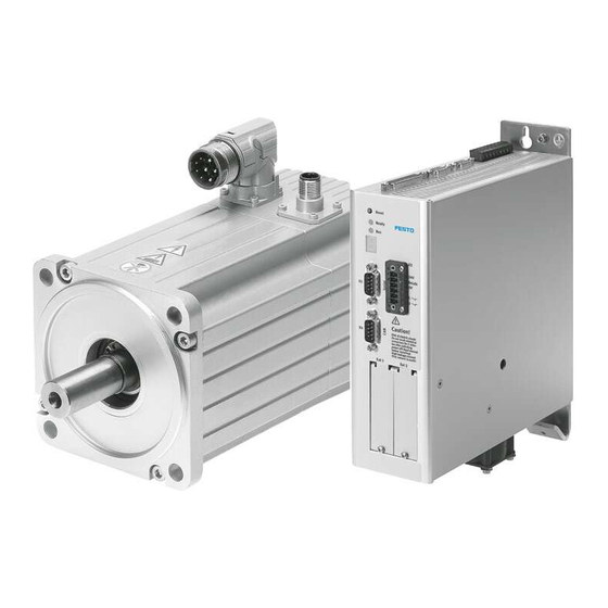
2. Hardware components 2. Hardware components 2.1 Motor controller The motor controllers of the CMMP-AS series are intelligent AC servo converters with extensive parametrisation possibilities and expansion options. This allows flexible use in a wide range of different applications. Further information on the CMMP-AS can be found in the documentation shown in section 1.3. -
Page 13: Connections X10/X11 And Connecting Cables
2.4.2 Input X10 At the input X10, besides another CMMP-AS, many additional, commercially available encoders can be connected, such as encoders corresponding to the industry standard ROD426 from Heidenhain or encoders with single-ended TTL outputs as well as “open- collector”... -
Page 14: Connecting Cable Between Master And Slave
Pin 5 is optional for cam disc operation (X11 -> X10) and does not have to be connected. This pin is only used to supply external encoders. 2.4.4 Topology of the connections between master and slave(s) A bus topology is recommended when connecting several slaves. Festo.P.BE-CMMP-CAM-SW-EN en 1105a... -
Page 15: Parametrisation Software
– one plug-in each for the special requirements of a component with the necessary descriptions and dialogues. Included in the scope of delivery of the CMMP-AS is a CD with the FCT framework. If it has not yet been done: Install the FCT framework on your computer (system requirements: see CD wrapper). -
Page 16: Fct Plug-In Cmmp-As
The following figure shows selection of the plug-in version when adding a component to a new or existing FCT project: As soon as the FCT with the plug-in CMMP-AS is installed on your computer, you can also install the cam disc function with help from the CD “GSPF-CAM-MC-ML”. Observe the instructions for installation on the CD wrapper. -
Page 17: Concepts Of The Cam Disc
The horizontal X-axis includes the position of the master, and the vertical Y-axis the position of the slave. And so a statement can be made at any time about the relationship between the two drives. X: Path master Y: Path slave Festo.P.BE-CMMP-CAM-SW-EN en 1105a... -
Page 18: Characteristics Of The Cam Disc Function
4. Concepts of the cam disc 4.2 Characteristics of the cam disc function The cam disc function implemented in the device family CMMP-AS has the following characteristics: – High flexibility of the system. A conversion of the mechanical system for different requirements of the curve shapes is no longer necessary. -
Page 19: Physical Master
If the “physical master” is activated for the slave, additional specifications on the encoder can be made. This does not apply if the master is a CMMP-AS, since the standard settings are already oriented on this. See also section 2.4 Connections X10/X11 and connecting cables. -
Page 20: Virtual Master
4. Concepts of the cam disc 4.4 Virtual master A “virtual” master runs as software on a CMMP-AS that was configured accordingly. As a result, this CMMP-AS is simultaneously master and slave. The master carries out positioning jobs (e.g. positioning records from the positioning record table) only “virtually”, i.e. -
Page 21: Master-Slave Constellations
4. Concepts of the cam disc 4.5 Master-slave constellations In the following, options for how several CMMP-AS can work together in one cam disc application are shown as examples. 4.5.1 CMMP-AS as physical master with 3 slaves Master: In the master, no cam disc is active, that is, the axis connected to it performs exactly the positioning jobs that are specified by record selection or direct operation. -
Page 22: Cmmp-As As Virtual Master With One Slave
4. Concepts of the cam disc 4.5.2 CMMP-AS as virtual master with one slave Slaves can also be connected to a CMMP-AS that was configured as a virtual master. In FCT, it can be set whether at X11 – the signal of the virtual master or –... -
Page 23: Modulo Positioning
With a physical master, after activation of the modulo function, only the upper and lower area limit have to be specified. The upper limit of the travel range is never being taken; upon reaching the upper range limit, the slave controller automatically switches to the lower range limit. Festo.P.BE-CMMP-CAM-SW-EN en 1105a... -
Page 24: Modulo Positioning With Virtual Master
In the case of target positions outside the modulo range, positioning is executed as a normal, absolute positioning job. The upper range limit does not belong to the valid range. In this case, enter the lower range limit as target position. Festo.P.BE-CMMP-CAM-SW-EN en 1105a... -
Page 25: Electronic Gear Unit Between Physical Master And Slave
Example: The physical master travels from its position 0 to position 2. In FCT, a transmission ratio of 1:2 was parametrised for the slave (input speed:output speed). Setting for the slave in FCT: Festo.P.BE-CMMP-CAM-SW-EN en 1105a... - Page 26 Assuming that the master sends 1024 increments per revolution, but only 512 increments are parametrised for the slave, the slave will assume with every revolution of the master that the master made two revolutions (if 1:1 is entered as the transmission ratio). Festo.P.BE-CMMP-CAM-SW-EN en 1105a...
-
Page 27: Basic Parameters For A Cam Disc
4.8 Basic parameters for a cam disc Overview: Reference value for dynamic calculations Limit value for speed Limit value for acceleration The basic parameters are explained in detail in the online help of the FCT plug-in (menu “Help / Dynamic Help”). Festo.P.BE-CMMP-CAM-SW-EN en 1105a... -
Page 28: Displacement Plan Editor
In calculating the dynamic values, the editor takes into account the parametrised limit values of the drive and, if certain speeds/accelerations are exceeded, the editor reports “conditions violated”. The master would then have to run through the cam disc more slowly to reduce the accelerations/speeds of the slave. Festo.P.BE-CMMP-CAM-SW-EN en 1105a... -
Page 29: Displacement Plan Editor <-> Conventional Curve Creation
The question whether the acceleration and jerk values that occur will overload the drive can only be clarified through complex individual calculations. The Festo displacement plan editor, in contrast, makes it possible to set only central design points by mouse-click. The remaining course of the curve is recommended by the program. - Page 30 Note on terminology: There are 2 types of data points (also called nodes): – the design points, which the user generates by mouse-click in the displacement plan editor, – the grid points automatically generated during rasterisation of the curve. Festo.P.BE-CMMP-CAM-SW-EN en 1105a...
-
Page 31: Endless And Finite Cam Discs
In such situations, the displacement plan editor reports when closing that the process shows a jerk at 0/360. Festo.P.BE-CMMP-CAM-SW-EN en 1105a... - Page 32 4. Concepts of the cam disc The curve overall is considered defective (“conditions violated”), see the following figure: With the following curve, the first and last design point are placed directly on the end positions of the master period: Festo.P.BE-CMMP-CAM-SW-EN en 1105a...
-
Page 33: Creating A Curve And Selecting A Motion Law
The result is approximately the following figure: Repeat the process and insert a dwell again further to the right and up in the path diagram. The editor automatically connects the two dwell sections with curves. The result is approximately the following curve: Festo.P.BE-CMMP-CAM-SW-EN en 1105a... - Page 34 If you wish to delete a dwell: Click on the symbol for the wastebasket and then on a design point. The dwell is deleted completely. In the same way, you can also delete every other design point. Festo.P.BE-CMMP-CAM-SW-EN en 1105a...
- Page 35 In the following example, the uniform distribution of points results in a symmetrical curve with 4 sections: two dwell phases (<II> and <IV>), a phase in which the drive travels in a positive direction (<I>), and a phase in which the drive travels in a negative direction (<III>): Festo.P.BE-CMMP-CAM-SW-EN en 1105a...
- Page 36 You can select a different motion law for every section of a curve: With the right mouse button, click in the third section (travel in a negative direction). The related dialog window is opened. Enter “34” as the motion law (= polynomial 7th order) and click on “OK”. Festo.P.BE-CMMP-CAM-SW-EN en 1105a...
- Page 37 The comparison between the first and third section shows what effects the various motion laws have on the course of the curve: With the 7th-order polynomial, the rise of the acceleration (lowest red curve in the following figure) is slower/flatter than with the modified sine. Festo.P.BE-CMMP-CAM-SW-EN en 1105a...
- Page 38 4. Concepts of the cam disc Through the menu command “Output/individual movement diagram”, you can also view the related jerk (yellow line): The jerk course is markedly more harmonious with the 7th- order polynomial. Festo.P.BE-CMMP-CAM-SW-EN en 1105a...
-
Page 39: Fundamentals On Selection Of The Motion Laws
48 or 49 can be used. But these have relatively high jerk values, which could have negative effects on vibration tendency and the load of the mechanical system. Festo.P.BE-CMMP-CAM-SW-EN en 1105a... - Page 40 4. Concepts of the cam disc The characteristics of all 55 motion laws with their specific advantages and disadvantages are explained individually in the displacement plan editor help. Festo.P.BE-CMMP-CAM-SW-EN en 1105a...
-
Page 41: Additional Basic Logic Functions
Click on a section with the right mouse button and, in the dialog, enter the percentage straight-line share for this section. The percentage refers to the length of the section. The straight line is inserted in the middle. The following course results: Festo.P.BE-CMMP-CAM-SW-EN en 1105a... - Page 42 In the dialog windows of the two data points of the straight-line section, you can, for example, determine that the jerk at the start or end of the segment should “= 0”: You can also enter the lead or speed in the dialog window of the straight-line section. Festo.P.BE-CMMP-CAM-SW-EN en 1105a...
- Page 43 With this function, you must first define a range by clicking twice in the path diagram. Then you can add a curve from a stored value table to this section. In various dialogs, you have the option to edit the imported data, adjust the size of the curve and smooth it. Festo.P.BE-CMMP-CAM-SW-EN en 1105a...
- Page 44 Alternatively, you can click again on the button and adjust the positions in the related dialog. Deleting: To delete a reference line, use the wastebasket button from the menu bar or the relevant reference line button again with the related dialog. Festo.P.BE-CMMP-CAM-SW-EN en 1105a...
-
Page 45: Further Optimisations
In the following example, in the right figure, the start of the movement was moved forward and the end of the movement was moved backward. A markedly flatter acceleration curve results, even though the drive practically stands still in the area of the previous dwell. Festo.P.BE-CMMP-CAM-SW-EN en 1105a... - Page 46 Tip: With the button “Edit parameters of displacement plan” in the dialog for basic settings, you can activate an online drag mode through the setting “Drag mode with maximized course with svaj diagram?” (only recommended for fast computers). Festo.P.BE-CMMP-CAM-SW-EN en 1105a...
- Page 47 You can set this in the related section dialog using the “inflection point parameter”: Sections always go from 0…1. A value of 0.5 represents the centre of the section, a value of 0.25 precisely the limit of the front quarter. Enter the values with a point as decimal separator. Festo.P.BE-CMMP-CAM-SW-EN en 1105a...
-
Page 48: Cam Switch
The start and end of cams can only be on grid data points. If there are high requirements for the switching precision of cams, a large number of grid data points must be specified. See section 4.9.3 Rasterisation of the curve. Festo.P.BE-CMMP-CAM-SW-EN en 1105a... - Page 49 The cams can either be interrogated via FHPP or mapped onto digital outputs. Interrogation via FHPP: You can read the status of the cams (actuated/not actuated) out of the PNU 311/02. See FHPP description according to section 1.3 Documentation overview CMMP-AS. Festo.P.BE-CMMP-CAM-SW-EN en 1105a...
-
Page 50: Setting Digital Outputs
On the “Application Data” page in the “Operating Mode Settings” tab: Activate “Position Trigger”. On the “Position Trigger” page: Assign the desired cam switch (here no.1) to a position trigger (here: #1). On the “Digital Outputs” page: Assign Position Trigger #1 to a digital output (here: DOUT2). Festo.P.BE-CMMP-CAM-SW-EN en 1105a... -
Page 51: Activating Cam Discs
DIN3 is set. In the “Assignments” tab, you can then establish possible double assignments of the digital inputs: Note Multiple assignment of digital inputs should be avoided. Functions/signals with high priority can prevent activation of a curve. Festo.P.BE-CMMP-CAM-SW-EN en 1105a... - Page 52 Grey: The input is not assigned. Green: The input is assigned once. Yellow: The input is assigned twice. Red: The input is assigned at least three times. For activation of cam discs via fieldbus: See chapter 6. Festo.P.BE-CMMP-CAM-SW-EN en 1105a...
-
Page 53: Position Comparison Between Master And Slave
Subsequently, the connected axis moves with CAM-IN velocity to Y=1. After completion of the CAM-IN movement, positioning records from the positioning record table can be executed “virtually”. The connected axis travels the path according to the active cam disc. Festo.P.BE-CMMP-CAM-SW-EN en 1105a... -
Page 54: Cam-In
For a combination of physical master and a slave: Note A cam disc should only be activated when the master is at rest! If the master moves during activation, this can result in setpoint jumps and following errors. Festo.P.BE-CMMP-CAM-SW-EN en 1105a... -
Page 55: Commissioning Examples
This documentation considers only the special aspects of the cam disc. The following step-by-step examples show how controllers of type CMMP-AS can be parametrised for a cam disc application. A requirement for verification of these examples is that the controllers, motors and axes are set up completely, wired and provided with electricity. -
Page 56: Example 1: Physical Master With A Slave
5.2 Example 1: Physical master with a slave Step 1 Insert two CMMP-AS into your FCT project (menu “Component / Add”). Call them “master” and “slave”, for example. Execute all parameter settings as well as commissioning as would be necessary without a cam disc. - Page 57 5. Commissioning examples Step 2 For the master: On the “Application Data” page in the “Operating Mode Settings” tab, activate the option “Encoder Emulation X11”. On the “Encoder Emulation” page: Check the settings and adjust them if necessary. Festo.P.BE-CMMP-CAM-SW-EN en 1105a...
- Page 58 The position comparison between master and slave is described in section 4.12. The modulo function is described in section 4.6. Under “Encoder Data (X10) ”, you can parametrise an “electronic gear unit”, see section 4.7. Festo.P.BE-CMMP-CAM-SW-EN en 1105a...
- Page 59 In the displacement plan editor: Create a curve. The first steps in creating a curve in the displacement plan editor are explained in section 4.9.5. After creation of the curve: Click on the “X” in the upper right to close the displacement plan editor. Festo.P.BE-CMMP-CAM-SW-EN en 1105a...
- Page 60 In FCT, the course of the curve is displayed in the Cam Switch. Insert cams if needed. Insertion of cams and display of the cam actuation using digital outputs is described in section 4.10. Step 6 Change to the “CAM-IN” tab and enter appropriate values. The CAM-IN movement is described in section 4.12.3. Festo.P.BE-CMMP-CAM-SW-EN en 1105a...
- Page 61 If you selected the option “Reset master setpoint when activating a cam disc” in the “Master” tab, the master specification is set to “0”. The slave travels with the CAM-IN parameters to its start position, in the example to “2.5”. Festo.P.BE-CMMP-CAM-SW-EN en 1105a...
- Page 62 In the master, enter a positioning record, e.g. for travel from position 0 to 5, and execute the positioning record. The slave will travel from position 2.5 to 7.5 according to the cam disc displayed under step 5. Festo.P.BE-CMMP-CAM-SW-EN en 1105a...
-
Page 63: Example 2: Virtual Master
5. Commissioning examples 5.3 Example 2: Virtual master Step 1 Insert a CMMP-AS in your FCT project. Parametrise it completely and execute commissioning, as is necessary even without the cam disc function. Warning Electric axes can move suddenly with high force and at high speed. - Page 64 “Component/Restart Controller” (especially for CANopen applications, since a CAN reset is usually sent here before a start). Then set the FCT device control (“FCT” and “Enable”). Execute homing (if necessary). Festo.P.BE-CMMP-CAM-SW-EN en 1105a...
- Page 65 “Cam” tab. The connected drive travels to its start position with the CAM-IN parameters. Step 8 Enter a positioning record on the “Positioning Record Table” page and execute the positioning record. The connected drive travels the curve depicted under step 5. Festo.P.BE-CMMP-CAM-SW-EN en 1105a...
-
Page 66: Control Via Fhpp
6. Control via FHPP 6. Control via FHPP The CMMP-AS has the option to manage 16 cam discs with 4 assigned cam switches each. This chapter describes how this function can be used with the help of FHPP. The CMMP-AS offers the option to implement the following applications over FHPP: 1. -
Page 67: Overview Of Parametrisation: Physical Master With Slave (Fnum=1/2)
(The cam disc number can also be mapped in FHPP+). 3. Start: The cam disc mode is started through a rising edge at the START bit CPOS.B1. Examples for configuration of the controller: see section 6.9.4 and 6.9.5. Festo.P.BE-CMMP-CAM-SW-EN en 1105a... -
Page 68: Overview Of Parametrisation: Virtual Master (Fnum=3)
CDIR.B1 and B2 must be at 0 (always position control). 2. The virtual master is active as soon as a rising edge occurs at CPOS.B1 START. Examples for configuration of the controller: see section 6.9.6. Festo.P.BE-CMMP-CAM-SW-EN en 1105a... -
Page 69: Configuration Of The I/O Data
Byte 1 Byte 2 Byte 3 Byte 4 Byte 5 Byte 6 Byte 7 Byte 8 Output Setpoint CCON CPOS CDIR Setpoint value 2 data value 1 Actual Input data SCON SPOS SDIR Actual value 2 value 1 Festo.P.BE-CMMP-CAM-SW-EN en 1105a... -
Page 70: Overview: Assignment Of The Control Bytes And Status Bytes
Function number e/Relati function (position, force …) *) only for direct operation. In the case of record selection, the record number is transferred in control byte 3. The function of CDIR then takes over PNU 401 + subindex. Festo.P.BE-CMMP-CAM-SW-EN en 1105a... -
Page 71: Status Bytes
*) only for direct operation. In the case of record selection, the record number is transferred in status byte 3. The RSB (record status byte) is then transferred in status byte 4. Festo.P.BE-CMMP-CAM-SW-EN en 1105a... -
Page 72: Description Of The Control Bytes
START edge. Fahrauftrag Positioning The START bit can then be reset again without ending the cam Task disc mode. This applies correspondingly for pure synchronisation as well (for FNUM=1). … Festo.P.BE-CMMP-CAM-SW-EN en 1105a... -
Page 73: Control Byte 3 Cdir (Only For Direct Operation)
= 0: Normal job FUNC ausführen FUNCtion = 1: Execute function (bit 3…6) For the function numbers 1 and 2 (pure synchronisation or synchronisation with cam disc), the bits B0 … B2 are not relevant (always position control). Festo.P.BE-CMMP-CAM-SW-EN en 1105a... -
Page 74: Description Of The Status Bytes
Description Halt HALT = 0: Halt is active HALT = 1: Halt is not active, drive can be moved Bestätigung ACKnowledge = 0: Ready for start (homing, jog) Start Start = 1: Start executed (homing, jog) … Festo.P.BE-CMMP-CAM-SW-EN en 1105a... -
Page 75: Status Byte 3 Sdir (Only For Direct Operation)
Function Group B5 – B6 are interpreted together as a number. FGRP Funktions- Value Significance gruppe Synchronisation with/without cam disc Reserved Reserved Reserved Funktion Function = 0: Normal job FUNC = 1: Function is executed (bit 3…6) Festo.P.BE-CMMP-CAM-SW-EN en 1105a... -
Page 76: Record Selection
= 1: Function / execute macro ( FGRP / FNUM ) For FNUM=1 or 2, bit 0 … 2 are without significance (always position control). For FNUM =3, bit 0 applies for the virtual master, bit 1 and 2 are without significance (always position control). Festo.P.BE-CMMP-CAM-SW-EN en 1105a... -
Page 77: Record Status Byte Rsb
Reserved Bit 7 Funktion Function = 0: Normal job FUNC = 1: Function is executed (bit 0..6 = function number) Bit 0 and 1 are of significance only for virtual master (FNUM=3) if record chaining was parametrised. Festo.P.BE-CMMP-CAM-SW-EN en 1105a... -
Page 78: Description Of The Parameters (Pnu 700
CamID (cam disc number) Description The cam disc is selected with this parameter. Value range 1 ... 16 Read/write FHPP Optional int32 Name DE/EN Masterstartposition Description For virtual master, establishes the start position of the master. Read/write Festo.P.BE-CMMP-CAM-SW-EN en 1105a... - Page 79 6. Control via FHPP FHPP Optional uint32 Name DE/EN Eingangskonfiguration Synchronisation Input Config Sync. Description For CMMP-AS: Function Values Ignore zero pulse Bit 0 = 1: without zero pulse bit 0 = 0: with zero pulse Reserved – Switch off A/B track...
- Page 80 Optional uint32 Name DE/EN Ausgangskonfiguration Output Config Encoder Emulation Encoderemulation Description For CMMP-AS: Function Values Switch off A/B track Bit 0 = 1: without A/B track bit 0 = 0: with A/B track Suppress zero pulse Bit 1 = 1: without zero pulse...
-
Page 81: Examples For The Control And Status Bytes In Fhpp
6.9.3 Record selection - synchronisation on virtual master with cam disc function (FNUM=3) 6.9.4 Direct operation - synchronisation on input X10 (FNUM=1) 6.9.5 Direct operation - synchronisation on input X10 with cam disc function (FNUM=2) 6.9.6 Direct operation - synchronisation on virtual master with cam disc function (FNUM=3) Festo.P.BE-CMMP-CAM-SW-EN en 1105a... -
Page 82: Record Selection - Synchronisation On Input X10 (Fnum=1)
4. Stop: takes place through removal of the STOP bit. The status of the START bit is not relevant thereby. To restart, first the bit SCON.B1 OPEN is required and then a new START edge. An intermediate stop is not possible. Setting of the HALT bit results in stopping (HALT = STOP). Festo.P.BE-CMMP-CAM-SW-EN en 1105a... -
Page 83: Record Selection - Synchronisation On Input X10 With Cam Disc Function (Fnum=2)
START bit is not relevant thereby. To restart, first the bit SCON.B1 OPEN is required and then a new START edge. An intermediate stop is not possible. Setting of the HALT bit results in stopping (HALT = STOP). Festo.P.BE-CMMP-CAM-SW-EN en 1105a... -
Page 84: Record Selection - Synchronisation On Virtual Master With Cam Disc Function (Fnum=3)
OPEN is required and then a new START edge. There is an option to force an intermediate stop during movement through removal of the HALT bit. The HALT bit stops the virtual master. A new positive start edge is needed for starting. Festo.P.BE-CMMP-CAM-SW-EN en 1105a... -
Page 85: Direct Operation - Synchronisation On Input X10 (Fnum=1)
START bit is not relevant thereby. For restarting, the status bit SCON.B1 OPEN must be set. Then the START bit can be set again. An intermediate stop is not possible. Setting of the HALT bit results in stopping (HALT = STOP). Festo.P.BE-CMMP-CAM-SW-EN en 1105a... -
Page 86: Direct Operation - Synchronisation On Input X10 With Cam Disc (Fnum=2)
6. The new parameters are transferred with a new rising edge at the START input. Previously, the START bit must be set to 0. With a rising edge, the new cam is transferred immediately. Note: The master should be at rest when a cam disc is activated. Festo.P.BE-CMMP-CAM-SW-EN en 1105a... - Page 87 START bit is not relevant thereby. For restarting, the status bit SCON.B1 OPEN must be set. Then the START bit can be set again. An intermediate stop is not possible. Setting of the HALT bit results in stopping (HALT = STOP). Festo.P.BE-CMMP-CAM-SW-EN en 1105a...
-
Page 88: Direct Operation - Synchronisation On Virtual Master With Cam Disc Function (Fnum=3)
6 are fulfilled. 6. The new parameters are transferred with a new rising edge at the START input. Previously, the START bit must be set to 0. With a rising edge, the new cam is transferred immediately. Festo.P.BE-CMMP-CAM-SW-EN en 1105a... - Page 89 This is different with the intermediate stop. Here there is the option to force an intermediate stop during movement through removal of the HALT bit. The HALT bit stops the virtual master. A new positive start edge is needed for starting. Festo.P.BE-CMMP-CAM-SW-EN en 1105a...
-
Page 90: Finite State Machine Fhpp Incl. Cam Disc
7. Finite state machine FHPP incl. cam disc 7. Finite state machine FHPP incl. cam disc Festo.P.BE-CMMP-CAM-SW-EN en 1105a... - Page 91 START – Rising edge at START PNU 700 was changed. automatically starts FUNC=1. the virtual master. TA 17 Intermediate HALT = 0 Only for virtual master. stop TA 18 HALT = 1 intermediate stop Festo.P.BE-CMMP-CAM-SW-EN en 1105a...
Need help?
Do you have a question about the CMMP-AS and is the answer not in the manual?
Questions and answers