Advertisement
Quick Links
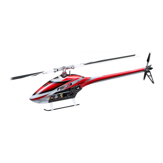
JR's EXTREME 3D MODEL
JR's EXTREME 3D MODEL
Specifications
Length
1,332mm Main rotor blades 710mm
Height
356mm
Width
210mm
Gross weight 3,500g 〜 ※ not including battery
CONTENTS
1.
Introduction
........................................................................................................................... P.2 - P.5
2.
3.
Tools required for assembly, Useful tools, Universal links, Indication of temporary fixation
4.
Nut and bolt types, Prevention of loosened bolts, Tightening bolts, Grease, Instant adhesive agent, Sanding, Assembly hints
5.
Assembly procedure 1
6.
Assembly procedure 2
7.
Assembly procedure 3
8.
Assembly procedure 4
9.
Assembly procedure 5
10.
Assembly procedure 6
11.
12.
13.
When repair is necessary
14.
Servo horn neutral adjustment
15.
Setting and adjustment of the transmitter
16.
Final checks prior to flight
17.
18.
Read prior to flight
19.
Parts list
........................................................................................................................... P.44 - P.57
20.
Product warranty and indemnification of liability
21.
Main shaft dia.
∅ 12
Main rotor dia.
1,599mm Control system
............................................................................................................... P.5
......................................................................................................... P.8 - P.10
......................................................................................................... P.11 - P.16
......................................................................................................... P.17 - P.18
......................................................................................................... P.19 - P.24
......................................................................................................... P.25 - P.29
......................................................................................................... P.30 - P.31
.......................................................................................... P.32
................................................................................................... P.33
................................................................................................... P.34 - P.37
...................................................................................................... P.38
................................................................................................... P.41 - P.41
.............................................................................................P.41
............................................................................................................ P.42 - P.43
...................................................................................................... P.59
Tail output shaft dia.
Tail rotor dia.
........................................................................... P.39 - P.40
........................................................................... P.58
ASSEMBLY MANUAL
This photo depicts an assembled model
∅ 6
Gear ratio
288mm
Li-po battery 6 cell × 2
120° CCPM Tail drive system : Shaft drive
10.18 : 1 : 4.72
.................. P.6
P.7
Advertisement

Related Manuals for JR FORZA 700


Summary of Contents for JR FORZA 700
-
Page 1: Table Of Contents
ASSEMBLY MANUAL JR's EXTREME 3D MODEL JR's EXTREME 3D MODEL This photo depicts an assembled model Specifications Length 1,332mm Main rotor blades 710mm Tail output shaft dia. ∅ 6 Gear ratio 10.18 : 1 : 4.72 Height 356mm Main shaft dia. ∅ 12 Tail rotor dia. 288mm Li-po battery 6 cell × 2 Width 210mm Main rotor dia. 1,599mm Control system 120° CCPM Tail drive system : Shaft drive Gross weight 3,500g 〜 ※ not including battery... - Page 2 Introduction Thank you for purchasing this JR product. The FORZA 700 is an electric helicopter perfect for advanced and 3D flyers. Please be sure to understand the instructions in this manual before commencing assembly. Be sure to observe these safety precautions Do not assemble or fly this helicopter without seeking expert assistance. Be sure to receive guidance from our dealer or an advanced pilot. An instructor helping you is requested to fully observe not only the instructions and precautions in this manual but also the rules and guidelines for flight. In order to prevent fire or injury, always observe the stated safety precautions each time you go flying. The manual describes warnings, dangers and cautions for safe assembly and flying. They are very important. The following symbols are used to indicate the precautions for preventing accidents due to erroneous handling of this product. Please be sure to follow these instructions. DANGER Neglect of this precautionary notice is very likely to result in death or serious injury to the user. WARNING Neglect of this precautionary notice is likely to result in death, serious injury or damage to property. NOTE Neglect of this precautionary notice is not likely to result in death or serious injury but may result in injury or damage to property. Take guidance from our dealer or advanced pilot This helicopter is not a toy. If you are a beginner with R/C helicopters, or if you are unfamiliar with electric powered models, do not try to assemble or fly this model by yourself. Because many parts are already assembled, it may look simple and easy to operate. However, it actually requires extremely delicate assembly, adjustment and operation. Take appropriate guidance from our dealer or an advanced pilot so that you can enjoy flying this model and experience its full performance. If you cannot complete the assembly by yourself, it is recommended you take guidance from our dealer or an advanced pilot. When you first fly the model, be sure to ask for assistance. Flying the helicopter alone may involve great danger to yourself or others, as well as damaging the helicopter. Getting proper guidance helps prevent accidents and damage. Also, please pay close attention to the use and care of peripheral equipment including the battery, charger, etc. Buy a radio control insurance policy Please be sure to purchase a "radio control insurance policy". For details, please inquire with our distributors or an insurance agent. Be careful when handling parts such as the battery or charger Improper handling may result in electric shock, burn, explosion, or fire. Do not use the charger or batteries near an open flame. If a power generator is used, do not use an open flame near it, the fuel, or any related devices.
- Page 3 Precautions for handling ● Immediately after flight, the motor, speed control and battery are very hot. Be careful to avoid a fire or burn. ● Accessories such as the battery and electrical parts should be handled with care. If the insulation is torn or the connector is shorted, you could be burnt or injured. Read the instructions for use of such accessories before handling. ● Do not charge or discharge the battery near an open flame or in a hot environment. ● Unnecessary disassembly or modification of any components are strictly prohibited. Neglect of this could result in a fault and /or accident. ● Stop and unplug the motor before doing the following actions: ① When you make adjustments to the helicopter or the control sysytem. ② When you replace any accessories or parts. ③ When the helicopter has something wrong or when you note unusual noise, smell or vibration. ④ When danger is expected. ● Use parts only within their service limits, if indicated. ● In order to realize a pleasant flight, try to keep appropriate gear backlash, movable parts moving smoothly, bolts tightened, and parts lubricated or replaced as required. Precautions for safe flight The model could crash due to slight assembly failure, operational mistake, service failure (loose bolts, etc.), interference and so on. Always keep in mind that the radio control helicopter which is controlled by radio frequency, may go out of control for some reason, and the operator should pay attention to himself/herself and the surrounding environment at all times for safe flying. ◎ To fly the helicopter, it is necessary to fully master operational skills for flight as well as basic flight methods. Receive guidance from our distributor or an experienced pilot and operate under their instructions. ◎ If you notice an abnormality before flight, be sure to eliminate the cause before flying. ◎ If two or more radio devices are used simultaneously on the same frequency, you can not operate the helicopter because of interference. If someone else is using the same frequency, operation may stop. If there is interference despite no one using the same frequency, a source of interference exists. Never fly until this interference has been cleared. Flying site and range ① The flying range of the helicopter can be defined as the distance where it can receive the radio frequency signal from the transmitter. However its true range is limited to where you can confirm the behavior of the helicopter with your own eyes. ② Never operate the helicopter in a place where you may lose sight of it, or the radio signal from your transmitter fails to reach it - as a crash is very likely. ③ Try to understand the surroundings at all times and never fly in bad weather, such as strong wind or rain, at night or in low visibility. ④ Never fly in a place where there are people, cars, schools, hospitals, other buildings or obstacles, or by a river or on the seashore; fly at an exclusive airfield where radio signals are controlled. ⑤ Do not fly near roads, tracks, electric lines, high-tension lines or other objects determined dangerous. ⑥ Please do not let the noises of main rotor blades or other parts disturb the surroundings. Observe these rules and manners to help enjoy this R/C helicopter. Precautions for the operator The following items are precautions for the operator flying this R/C helicopter. Be sure to observe them. ① The following persons or those in the following states should never operate this helicopter: ● Infants, children, or other persons who have no knowledge or experience of R/C helicopters. ● Pregnant woman.
- Page 4 ● In order to protect your feet, wear solid, easy-to-move shoes, avoiding sandals or high-heel shoes. ● Wear a cap, gloves, sunglasses or goggles as required. ③ Do not fly the Helicopter in an unnatural posture. ● Avoid standing in an unstable or slippery position. ● Do not fly while looking backward, sitting or lying. ● Do not bring the helicopter too close to the operator or surrounding people (if there are bystanders, make sure that they are behind the operator). ④ Take sufficient flight breaks. ● An excessively long flight makes the operator lose his/her concentration due to fatigue, leading to accidents. Take adequate flight breaks. Avoid an unreasonably long flight, which could result in unexpected accidents or injuries. Precautions for starting ① Make sure the bolts for the blades (main rotor, tail rotor) are properly tightened - there should be some movement possible. Check all other screws to confirm they are properly tightened. Retighten any loose screws. ② Make sure that no tool used for assembly or adjustment has been left in the helicopter body, and that all parts affecting flight performance are free from fault. ③ Keep the airfield as neat and tidy as possible and place the helicopter in a stable place (objects such as cables, wires, strings, debris of broken parts, screws, etc., may be scattered by the wind pressure from the rotor and damage the helicopter). ④ Make sure that the batteries in the transmitter and the receiver are fully charged. ⑤ Always turn on the transmitter first. ⑥ Conduct a distance (range) test of the transmitter. Follow the directions of your transmitter manufacture. Move the controls and confirm movement of the helicopter servos. If they do not move properly, check the cause and have it repaired, if necessary. ⑦ a. Extend the transmitter's antenna to its full length. Put the receiver's antenna through an antenna tube and make sure that it can easily receive the radio signal, ensuring it cannot be caught by moving parts (do not bend or bundle the antenna). b. When using a 2.4GHz transmitter, please adjust the antenna as directed in the manual supplied with the transmitter. ◎ Starting ① When moving to a take-off site, note that if your clothes contact the transmitter sticks, the rotor may suddenly start running. Please proceed with caution. ② When starting the motor, make sure that there is no person, animal or obstacle around the helicopter, which may be caught by the rotors. ③ After starting the motor, please understand setting the throttle stick / trim to slowest position stops the motor. Rising the rotation speed suddenly is very dangerous. Start the rotation gradually using the slow start function of the ESC. After the main rotor is rotating, abrupt stick operation will cause the helicopter to rise quickly. Please set the stick to medium-slow position and wait. Make sure the rise of the rotor speed follows your stick operation. ④ When lifting the helicopter into the air, be sure to remain at least 10m or more away from it. ⑤ Land before adjusting the transmitter or helicopter. Do not allow part of your body or clothes to contact the transmitter sticks by mistake, and do not put the transmitter down in a standing position because wind, etc. may tip the transmitter over, bumping the throttle stick, and causing the helicopter to suddenly leap into the air, endangering yourself or others. ⑥ Do not put your hand or any objects into the movable parts while they are running. ⑦ When checking the tracking adjustment stay at least 5m or more from the helicopter.
-
Page 5: Additional Items Required
③ When storing the helicopter for a long period of time, clean it before storage. ● Store it in a dry, safe place beyond the reach of infants or children. ● If there is damage or other problems, repair or replace components as necessary before storage. ④ To lubricate or replace parts, follow the relevant parts assembly processes in the manual and the instructions in the parts lists. ⑤ Check whether or not the receiver and gyro are firmly secured, and free from problems. ⑥ Check the receiver antenna wire from time to time because its core may become broken. This may not be immediately apparent, so have it checked periodically by the manufacturer. ⑦ Once your flying session is over, be sure to remove the battery from the helicopter. Replacement parts When replacing parts, use our specified original or our authorized optional parts. Do not modify these parts. Our product warranty does not cover any troubles resulting from use of non-original parts. Do not use out-of-standard parts, because they may cause an accident or a problem exposing you to great danger. Additional items required Transmitter (120 CCPM capable) Lithium-polymer battery (Li-Po) 6 cell ※ If you are using the JR TAGS 22.2V 4,500mAh 〜 × 2 mini, you will require the optional XBus adapter. Battery charger Brushless motor & ESC Battery connector set ESC /120A 〜 ※ Please see p.33 for details. KV : 500-520... - Page 6 Tools required for assembly JR digital pitch gauge Hex driver :1,5mm (NO.61401) (NO.61796) 2mm (NO.61402) 2.5mm (NO.61403) 3mm (NO.61404) Tape rule 4mm (NO.61598) 瞬間 CA Glue Thrust bearing grease Oil touch pen (NO.61296) (NO.61597) Other general tools required for making a model Sandpaper #300 〜 400 Useful tools JR Universal link driver JR Universal link trimmer JR Universal link plier C (NO.61360) (NO.60219) (NO.60242) Blade balancer Universal links The Universal links have a front and back and are mounted in the specified direction at the time of attaching the linkage. The following describes how to tell the front and back. At the time of attaching the linkage, pay attention to the direction of each universal link during assembly. JR PROPO The side marked "JR" is the front. At the time of fitting the linkage, attach the universal link to joint ball by pressing the back side onto the ball.
- Page 7 The following illustrates the bolts used for FORZA 700. ※ These are just examples for each type - several different sizes are used. Button head bolt Joint ball screw Socket head bolt Special socket head bolt Nylon lock nut Hex tapping screw Flat head bolt Setscrew Threaded rod Special washer Flat washer Prevention of loosened bolts Bolts may be loosened if they are exposed to vibration for a long period of time. For this reason, it is (×2) necessary to take proper countermeasures to prevent them from being loosened. In each process, the Green (×2) bolts and matching tapped holes marked with the symbols shown above should be degreased with alcohol and adhered with a screw locking agent such as JR Thread lock (green: hard, red: soft). The same applies for the parts marked with the same symbols. A parenthesized number added to the symbol indicates the number of bolts to be applied with the screw locking agent. If multiple pieces of the same part are used, the symbols including those for their bolts may be omitted. There are two kinds of screw locking agents. Green denotes a hard agent and red a soft one; use them properly, according to the instructions. When red (soft) agent is required, the mark is used, and when the green (hard) one is required, the mark is used. After assembly, if you want to remove the bolts, etc. secured with the screw locking agent, weaken the thread lock agent by adequately heating the bolt with a torch or a soldering iron (if you try to remove them by force, you may damage the bolt or wrench and fail to remove the part). When heating to loosen the screw locking agent, care should be taken not to deform the surrounding resin parts. Tightening bolts The bolts used for R/C Helicopter are rather small. If they are over tightened, the thread may be damaged. Please be especially careful when tightening the tapping screws into plastic parts. Grease Apply thrust bearing grease to the relevant parts marked with this symbol. Instant adhesive agent Bond the relevant parts marked with the following symbol, using an instant adhesive agent. (CA glue) As with the screw locking agent, a number "(x 2)" next to the symbol denotes the number of parts required to be adhered. (×2) Sanding Sand the parts where indicated with this symbol.
- Page 8 1-1 CARBON TRAY L ASSEMBLY Flat head bolt M3 × 8 ( × 6) Carbon tray L Tray bracket B ( × 3) ※ Temporarily tighten these Flat head bolts M3 × 8 - they are tighten firmly when the upper frame is installed. Plate cross member Tray bracket A ( × 3) Cross member L32 ( × 2) 1-2 RADIUS SUPPORT ASSEMBLY Radius support Radius support bracket Complete Assembly Button head bolt M3 × 8 ( × 2) Radius support rail...
- Page 9 1-3 MIDDLE CROSS MEMBER ASSEMBLY Middle cross member B Middle cross member A Carbon middle plate Flat head bolt M3 × 8 ( × 2) Flat head bolt M3 × 6 ( × 8) 1-4 BATTERY MOUNT PLATE RAIL INSTALLATION Flat head bolt M2.5 × 6 ( × 6) Battery mount plate rail ( × 2) Previously assembled...
- Page 10 1-5 MOTOR MOUNT ASSEMBLY Brushless motor (sold separately) ※ Temporarily tighten one setscrew M4 × 4 onto the D-cut on the motor shaft. If there is no D-cut, please file Motor mount one in an appropriate position. Next temporarily tighten the Pinion gear T11 second Setscrew M4 × 4. (standard) These are both tighten firmly ※ Pinion gear T12 when the upper frame is (Optional part - sold separately) installed. Setscrew M4 × 4 ( × 2) DANGER Button head bolt M4 × 8 ( × 4) Pinion bearing block assembly ※ Note the proper orientation Pinion nut M9 1-6 TAIL PINION UNIT ASSEMBLY Setscrew M3 ×...
- Page 11 2-1 CARBON UPPER FRAME ASSEMBLY Servo mount plate ( × 2) Button head bolt M2.5 × 6 ( × 2) Button head bolt M3 × 8 ( × 8) Cross member w/Step L32 ※ Temporary tighten these M3 × 8 bolts - tighten firmly when the drive gear is installed. Socket head bolt M3 × 8 ( × 8) Special washer M3 ( × 8) Servo mount ( × 4) Carbon upper frame ( × 2) Assembled in step Top bearing block assembly Middle bearing block assembly ※...
- Page 12 2-2 MOTOR MOUNT INSTALLATION Assembled in step 1-2 Socket head bolt M3 × 10 ( × 2) Tighten the setscrews which were previously temporarily tightened. Assembled in step 1-5 ※ Temporary tighten these bolts - tighten firmly when the drive gear is installed. Button head bolt M3 × 8 ( × 4) Button head bolt M4 × 8 ( × 4) Special washer M4 ( × 4) Socket head bolt M3 × 8 ( × 4) Special washer M3 ( × 6) P.12...
- Page 13 2-3 CARBON TRAY L AND MIDDLE CROSS MEMBER INSTALLATION HEX Tapping screw (black) M3 × 8 ( × 2) Gyro mount Body catch L21 ( × 2) Setscrew M3 × 15 ( × 2) Assembled in step 1-1 ※ Tighten the flat head bolts which were previously temporarily tightened. Button head bolt M3 × 8 ( × 8) Assembled in step 1-4 Flat head bolt M3 × 6 ( × 2) P.13...
- Page 14 2-4 CARBON LOWER FRAME ASSEMBLY Body catch L21 ( × 2) Carbon lower frame ( × 2) Socket head bolt M3 × 8 ( × 2) Landing strut adapter ( × 4) Socket head bolt M2.6 × 5 ( × 8) P.14...
- Page 15 2-5 UPPER AND LOWER FRAME CO-ASSEMBLY Carbon tray S Cross member L60 M2.6 ( × 2) ※ Sand the surface of the carbon tray where it is inserted into the slot of the lower Spacer L12 ( × 8) frame and use some CA glue to secure it. Socket head bolt M2.6 × 5 ( × 4) Button head bolt M3 × 20 ( × 8) P.15...
- Page 16 2-6 LANDING GEAR INSTALLATION Landing strut( × 2) Setscrew M4 × 4 ( × 4) Socket head bolt M3 × 10 ( × 2) Landing skid ( × 2) ※ Note the logo directions on the L and R landing skids. Landing skid cap ( × 4) 25mm P.16...
- Page 17 3-1 MAIN DRIVE GEAR ASSEMBLY Autrotation sleeve Shim washer 15 × 19 × 0.2 ( × 2) ※ Use 1 or 2 of these shim washers to eliminate any play Autrotation unit between the upper and lower ※ Note the proper drive gears (after the main orientation shaft is installed). Main drive gear T112 Flat washer M3 ( × 5) Button head bolt M3 × 8 ( × 5) P.17...
- Page 18 3-2 MAIN DRIVE GEAR, TAIL DRIVE GEAR, MAIN SHAFT COLLAR INSTALLATION Main shaft WARNING ※ Pull the main shaft up and push down on the main shaft collar. Make sure the main shaft is secured with no up-down movement. ※ The main shaft can be inserted around either way. Main shaft collar Setscrew M4 × 4 Previously Socket head bolt M3 × 10 assembled parts Nylon lock nut M4 (t3.8) Tail drive gear T104 Special socket head bolt M4 × 26 DANGER ※ Replace this bolt frequently ※ Note installation direction during maintenance. NOTE ※ Once the main gear is installed, adjust the main gear backlash. Use 2 layers of plastic parts bag as an adjustment guide. After the backlash adjustment is complete, tighten firmly the front 4 bolts of the tail pinion unit which were temporarily tightened in step 2-1, and the motor mount which was temporarily tightened in step 2-2. ※ Tighten firmly only the front bolts. P.18...
- Page 19 4-1 SWASH SERVO INSTALLATION Swash servo A Swash servo B Super horn ( × 3) Swash servo C Join ball screw L4 ( × 3) Nut M2 ( × 3) ※ Note the proper direction of the Joint ball screw for A servo. ※ Use the rubber isolators supplied with the servo. WARNING When tightening the bolts, the rubber grommets should be slightly compressed. Do not use the metal grommet inserts. HEX Tapping screw M2.6 × 12 ( × 4) Swash servo A Swash servo B Servo mount plate ( × 2) ※ If these servo mount plates are difficult to install because they touch the frame, trim as shown in the figure above. Servo layout Swash servo C Servo holding plate ( × 4) Socket head bolt M2.6 ×...
- Page 20 4-2 SWASH PLATE INSTALLATION ※ Insert the swash leveler and adjust the 3 linkages so the 14〜15mm servo horn become horizontal. JR PROPO Threaded rod M2.3 × 30 ( × 3) Universal link ( × 6) Swash plate assembly Joint ball shaft Control ball L5.5 ( × 6) Swash gauge ※ Once the linkage rods are installed, adjust the servos position and tighten the servo mounts which were previously temporarily tightened in step 2-1 P.20...
- Page 21 4-3 CENTER HUB INSTALLATION Flat head bolt M3 × 8 Head button Washer 4 × 11 × 1.7 ( × 2) Nylon lock nut M4 (t3.8) Center hub DANGER ※ Replace the bolts when performing maintenance. Socket head bolt M2.6 × 8 ( × 2) Special socket head bolt M4 × 26 P.21...
- Page 22 4-4 FBL WASHOUT ARM ASSEMBLY INSTALLATION Button head bolt M3 × 20 ( × 2) DANGER ※ Do not over tighten. FBL Washout arm assembly ( × 2) 4-5 MAIN BLADE HOLDER ASSEMBLY ※ Make two sets. Socket head bolt M3 × 12 ( × 2) Main blade holder assembly ( × 2) Socket head bolt M3 × 6 ( × 2) Pitch arm ( × 2) Control ball L5.5 ( × 2) P.22...
- Page 23 4-6 MAIN BLADE HOLDER INSTALLATION ※ The shim washers are used to Shim washer ( × 2) adjust a backlash when the mail Grip spacer ( × 2) blade holder is installed. Spindle washer M6 ( × 2) Damper rubber 90 ゜ ( × 2) Apply a small amount of oil. Previously assembled Socket head bolt M6 × 10 (Low profile) ( × 2) DANGER ※ Replace the bolts when Spindle shaft performing maintenance. P.23...
- Page 24 4-7 ROTOR HEAD LINKAGES 23.5mm ※ With the swash leveler installed, adjust the two linkages so the main rotor pitch angle is 0 ゜ . FBL universal link ( × 4) FBL threaded rod L45 ( × 2) P.24...
- Page 25 5-1 TAIL CONTROL ROD ASSEMBLY Tail control rod L740 Universal link ( × 2) Tail control rod end ( × 2) JR PROPO 20mm Tail control rod sleeve ( × 2) Approx. : 56mm 約 56mm Threaded rod M2.3 × 30 ( × 2) 15mm Toward front Toward rear 220mm 505mm 5-2 TAIL CONTROL ROD INSTALLATION Tail boom assembly ※ Temporarily tighten the tail control rod guides. Tighten firmly when the rudder servo is installed so the position matches the line of the tail control rod. Tail control rod guide ( × 2) Toward rear Setscrew M3 × 4 ( × 2) DANGER ※...
- Page 26 5-3 TAIL BOOM INSTALLATION Previouly assembled Button head bolt M3 × 4 Special washer M3 ( × 4) Metal tail boom holder Button head bolt M3 × 8 ( × 3) Button head bolt M3 × 25 ※ Temporarily tighten at this point and tighten firmly when the rear body is installed. 5-4 RUDDER SERVO INSTALLATION ※ Use the rubber isolators supplied with the servo. NOTE When tightening the bolts, the rubber grommets should be slightly compressed. Do not use the metal grommet inserts. Rudder servo Nut M2 HEX Tapping screw M2.6 × 12 ( × 4) ※ Attach the tail control rod to the rudder servo and tighten the setscrews which were temporarily tightened in step 5-2. Super horn Join ball screw L4 Servo holding plate ( ×...
- Page 27 5-5 FRP REAR BODY INSTALLATION Rear body clamp Socket head bolt M3 × 8 ( × 2) FRP rear body Button head bolt M3 × 4 ( × 4) Special washer M3 ( × 4) ※ File the mounting holes so that the rear ※ Tighten the button head body can mount smoothly. bolts (6) which were previously temporarily tightened. Bolts which were previously temporarily tightened. Spacer L11 ( × 2) Button head bolt M3 × 20 ( × 2) P.27...
- Page 28 5-6 TAIL GEAR CASE ASSEMBLY ※ The shims are used to eliminate any left to Tail output shaft right play in the tail output shaft. Poly slider 6 × 9.5 × 0.13 ( × 2) Bevel gear pin ∅ 2.3 Tail output shaft collar Bevel gear B T22 Setscrew M3 × 6 Tail gear case cross member Bevel gear A T22 Complete Assembly Tail gear case plate L Tail gear case plate R Tail gear case assembly Button head bolt M3 × 6 ( × 6) 5-7 TAIL PITCH CONTROL LEVER ASSEMBLY Tail slide ring bearing collar Tail slide ring sleeve WARNING Tail slide ring ※ Because it is reverse thread, beware the tightening direction. Shielded bearing 7 ×...
- Page 29 Thrust bearing 5 × 10 × 4 ( × 2) O-ring 3.5 × 5.5 × 1 ( × 2) Flat washer M3 ( × 2) Metal tail blade holder assembly ( × 2) Washer 8 × 10 × 0.5 ( × 2) Inner Dia. : Large No distinction of front and back Inner Dia. : Small NOTE ※ Apply a small amount of No.61597 JR Thrust bearing grease onto the thrust bearings. Socket head bolt M3 × 8 ( × 2) P.29...
- Page 30 6-1 BATTERY MOUNT PLATE ASSEMBLY Hook and loop strap ( × 4) To prevent the straps being damaged by sharp edges, we recommend sanding the slots on the Battery mount plate battery mount plate. Battery plate hook Battery mount plate Sanding the edges Flat head bolt M2.5 × 6 ( × 2) Hook and loop fastener L60 ( × 2) Battery (sold separately ) 6-2 BATTERY/GYRO/RECEIVER/ESC INSTALLATION Receiver (sold separately) Gyro (sold separately) ※ Please refer to p.32. Double side form tape (sold separately) ESC (sold separately) Remote antenna Previously assembled P.30...
- Page 31 6-3 FRP FRONT BODY INSTALLATION Snap pin 4mm ( × 4) Rubber grommet ( × 4) FRP front body Pass the snap pin through the hole in the body catch. 6-4 MAIN ROTOR BLADE INSTALLATION Main blade bolt M5 ( × 2) Rotor spacer AL t3 ( × 4) Main rotor blade ( × 2) (sold separately) Nylon lock nut M5 ( × 2) P.31...
-
Page 32: Installation Examples For Battery, Esc
INSTALLATION EXAMPLES FOR BATTERY AND ESC P.32... -
Page 33: Gear Ratio And Rotor Rpm Setup
GEAR RATIO AND ROTOR RPM SETUP Battery Pinion Gear Ratio Motor Approximate flight time (when using 5,000mAh) Pinion : Main KV value 1,500 〜 1,600rpm 2,000 〜 2,300rpm 10.18 : 1 12 cell approx. 8-10 mins approx. 3-4 mins 9.33 : 1 ※ T12 - sold separately Rotor RPM Hovering Flying 1,500rpm 〜 1,600rpm 2,000rpm 〜 2,200rpm 2,100rpm 〜 2,300rpm ※ In order to extend battery life, it is recommended to leave at least 15% battery capacity remaining after each flight. ● Battery Guide Li-Po Battery Cell Voltage / Capacity 6 Cell ×... - Page 34 When repair is necessary - MAIN BLADE HOLDER ※ Apply a small amount of No.61597 JR Thrust bearing grease onto the thrust bearings. Thrust bearing 10 × 18 × 5.5 Thrust washer Main blade holder Inner Dia. : Large No distinction of front and back Inner Dia. : Small Shielded bearing 10 × 19 × 7 ( × 2) When repair is necessary - FBL WASHOUT ARM ASSEMBLY Spacer 3 × 5 × 1.8 FBL Washout arm Setscrew M3 × 3 Flanged bearing F 3 × 7 × 3 ( × 2) E Stopper ring M1.5 ( × 2) Washout link pin...
- Page 35 When repair is necessary - TOP BEARING BLOCK ASSEMBLY / MIDDLE BEARING BLOCK ASSEMBLY Shielded bearing 12 × 24 × 6 Middle bearing block assembly Shielded bearing 12 × 24 × 6 Top bearing block assembly When repair is necessary - PINION BEARING BLOCK ASSEMBLY / MIDDLE CROSS MEMBER A Shielded bearing 12 × 24 × 6 Shielded bearing 10 × 19 × 7 Middle cross member A Pinion bearing block assembly P.35...
- Page 36 When repair is necessary - TAIL BOOM ASSEMBLY Apply a small amount of oil on the shaft if the shaft guide is difficult to install. Drive shaft Shielded bearing 8 × 14 × 4 ( × 2) Tail boom L813 Setscrew M3 × 10 ( × 2) Shaft drive guide ( × 2) Drive shaft joint ( × 2) 275mm 295mm When repair is necessary - TAIL PINION UNIT BEARING BLOCK ASSEMBLY / TAIL GEAR CASE ASSEMBLY Tail pinion unit bearing block Tail gear case bearing collar 7mm Tail gear case bearing collar 7mm Shielded bearing 12 × 18 × 4 ( × 2) Shielded bearing 12 × 18 × 4 ( × 2) Tail gear case P.36...
- Page 37 When repair is necessary - TAIL GEAR CASE PLATE L / TAIL GEAR CASE PLATE R Shielded bearing 6 × 13 × 5 Tail gear case plate L Tail gear case plate R Shielded bearing 6 × 13 × 5 When repair is necessary - HG METAL TAIL PC PLATE E Stopper ring M1.5 ( × 4) HG Tail PC link pin ( × 2 ) HG metal tail PC plate Tail PC link B ( × 2 ) When repair is necessary - TAIL PITCH CONTROL LEVER A / TAIL BLADE HOLDER Shielded bearing 6 × 10 × 3 ( × 2 ) Tail PC lever pin ( × 2 ) Flanged bearing F 3 × 7 × 3 ( × 2 ) Metal tail blade holder Tail pitch control lever A Setscrew M2 ×...
- Page 38 SERVO NEUTRAL ADJUSTMENT The servo horns should so far only be temporarily tightened. ① Disconnect the motor wires before making any adjustments. Turn on the transmitter first then turn on the receiver (helicopter). ② Confirm the transmitter sticks and trims are in the neutral position. If your transmitter has pitch trim levers, set these to neutral as well. Horizontal ③ Push down on the swash plate so it touches the ④ With the swash leveler installed, adjust the thread rod M2.3 swash leveler. x 30 so the servo horns become horizontal. 0° ⑤ Adjust the FBL thread rod L45 so the main rotor pitch ※ Note for zeroing your pitch gauge: Because this helicopter angle is 0 ゜ . has a front sloping main shaft, zero the pitch gauge as shown in this figure (on the head button, motor,carbon middle plate etc.) ⑥ Rudder adjustment Confirm the tail control rod is positioned at 90 degrees. If it is not, adjust the length of the tail control rod and the servo horn angle. View from side View from below 90° 90° P.38...
- Page 39 SETTING AND ADJUSTMENT OF THE TRANSMITTER 1 .【Rotor pitch setting】 ※ Please refer to the instructions supplied with your FBL control unit. Measure the pitch of the Main Rotor Blades using the JR digital pitch gauge (No.61796, sold separately). The intermediate (middle) value should be set to 0° - with the pitch stick in its middle position the pitch reading should be 0° . If it is not, adjust the length of the rods shown in the following figure to accurately set the pitch to 0° . Once the intermediate pitch has been adjusted to 0° by rod adjustment, measure the high and low pitch values. It is presumed that they are almost as described in the table. If they are slightly higher or lower, use the "swash type (mix)" function to adjust the pitch stroke (swash pitch mix % ). Increase or decrease the pitch percent value as required. In this case, the high and low pitches cannot be separately adjusted. If the above-mentioned intermediate pitch has been correctly adjusted, adjusting either the high or low pitch should automatically result in the figures seen in the table. If this is not the case, change the rod length and the pitch percent value in the swash mix, ignoring the intermediate value, so that the high and low pitches are properly adjusted. Low pitch Intermediate pitch High pitch ※ When confirming or adjusting the reference pitch Reference pitch -12° 0° +12° range, the pitch curve should be at default values. Hovering -5° +4° +12° Stunt -8° +3° +10° -12° 0°...
- Page 40 3 .【Throttle curve (Transmitter Throttle Curve Function)】 Adjust the throttle curve so the rotor rpm is as per the table on page 33 For details, please refer to your transmitter Instruction Manual and adjust the values accordingly. Please be extra careful not to turn on the motor. The throttle values here are just examples. In order to prevent over-speed of the main rotor, please adjust carefully after test flying the helicopter. ※ If your radio has a Throttle delay function, we recommend you to use this to prevent sudden changes in rotor speed when changing flight modes. Throttle curve Stick position High Stick position High 【Hovering】 【Stunt / 3D】 FINAL CHEKS PRIOR TO FLIGHT Although some items can only be adjusted after test flights, it is possible to do some final check prior to flight. Please recheck the following: ① Look through all the steps in the Instruction Manual again and make sure that all bolts are firmly tightened. Check in particular the bolts used for mounting the balls to the levers, and each bolt which was tightened after backlash adjustment ...
-
Page 41: Fine Adjustment Following Test Flight
FINE ADJUSTMENT FOLLOWING TEST FLIGHT 【Items which need to be readjusted after the test flight】 Tracking Adjustment This is to adjust both Main Rotor Blades to the same pitch, so each produces the same amount of lift. If they are not uniform, their trajectory is not seen as an identical line as shown in the figure below. This leads to vibrations and a helicopter which does not fly well. When the helicopter is about to leave the ground, look at the plane of rotation of the Main Rotor Blades from the side. No adjustment is required if the trajectory of the Main Rotor Blades is seen as an identical line. If vertically misaligned, pitch adjustment on one blade is required. On either the 'high' or 'low' blade adjust the Universal Link of the rod shown in the following figure in such a manner that the blade pitch is increased or decreased as required. Rod to adjust the pitch Tracking adjustment is dangerous. Remain at least 5m or more from the helicopter at all times. P.41... - Page 42 BE SURE TO READ PRIOR TO FLIGHT This helicopter is not a toy. It is intended for those having had prior experience flying a radio control helicopter, with appropriate knowledge and skills. Even an advanced operator well-versed in radio control helicopters may forget some safety precautions. Refresh your memory by reading the following. Fly the helicopter in a manner suitable for the operator's skills, avoiding any unnecessary risk during flight. For maneuvers demonstrated in a competition, emulate them after fully understanding and mastering the operating methods and skills required. When flying the helicopter, not only a beginner or intermediate operator, but an advanced operator should never fly alone. Listen to explanations from an assistant or an instructor having expertise, and fly under their instruction. 1.【Precautions after Assembly 】 ⓐ Check all bolts are fully tightened. Tighten any loose ones. ⓑ Be sure to use screw locking agent when tighten all bolts, if so instructed in the Instruction Manual. When doing this, degrease the bolts and nuts completely. ⓒ Check the rotating parts (Main Rotor Blades, Tail Rotor) and that their bolts are fully tightened. However it is necessary that the blades can be moved slightly back and forth. ⓓ Set the throttle stick to the slowest position, then turn on the transmitter (ensure it is fully charged). Next, turn on the helicopter by plugging in the main battery. Always turn on in this order. Operate the sticks (throttle/pitch, aileron, elevator and rudder) to confirm correct function. Always have the motor unplugged so that the motor will not turn on. ⓔ Never cut or bundle the antenna wire. Put it in the antenna tube so that it will not be caught by the rotor or the main gear. If a 2.4Ghz transmitter set is used, please adjust the antenna to the correct orientation as recommended in the radio manual. ⓕ Securely hold the helicopter with both hands when moving it. The helicopter has sharp parts (such as machined metal) pay attention to avoid injury. 2.【Precautions Prior to Flight 】 ⓐ Make sure that the Main Rotor Blades and Tail Rotor are free from any cracks or damage. If they are damaged even just a little, do not use them. ⓑ With the stick at the slowest position, turn on the transmitter then receiver and check for correct control movements. ⓒ Care should be taken not to catch your cloths on the transmitter sticks when moving the helicopter. Move the helicopter to the takeoff position using two or more persons - one holding the helicopter with both hands and the other carrying items required for flight, such as the transmitter.
- Page 43 ⓒ Keep your eyes on the helicopter during flight. If you look away even for a short period of time, it may change its position or you may lose sight of it and loose control. ⓓ Do not fly (or hover) with the Main Rotor Blades at eye level because it is dangerous. Always ensure that the Main Rotor Blades are higher than eye level. ⓔ Be careful not to exhaust the battery power. Use the timer function on the transmitter, keep the remaining battery power under check. ⓕ When stopping the Main Rotor Blades never touch them. Wait for them to stop naturally. ⓖ If you notice an abnormality during flight, land the helicopter immediately and check for any loose bolts, etc. Do not fly it again until the cause has been completely eliminated. ⓗ In a crash parts like the Li-Po battery or the ESC in the helicopter could catch fire. Keep a fire extinguisher near during flight for safety and fire prevention. ⓘ Other adjustments and notices will be updated at any time on the following website. Introduction and setting methods for recommended ESCs and Motors are also on this website. Please check it for more information. http://www.jrpropo.com/english/heli/forza700/ 4.【Precautions after flight】 ⓐ Check for any loose bolts or shaky parts. If there is any abnormality, repair them before the next flight. ⓑ If the Main Rotor Blades or any other part come into contact with the ground during flight, do not use those parts even if their appearance looks faultless. Replace them with new ones. ⓒ Check whether or not the battery, receiver, gyro, etc. are firmed secured. ⓓ Check the antenna wire from time to time because its core may have been broken. If broken within the coating, it may not be immediately apparent. Refer to the manufacturer periodically for servicing. P.43...
- Page 44 61935 61933 80095 70664 70719 80164 80015 80181 70758 70776 80075 96452 61937 80012 80115 96344 61934 61936 80259 81041 70759 81016 70119 70620 70760 81017 81005 80067 80260 80264 70010 70657 61938 80013 80193 80257 96459 61939 70004 05015 80258 96459 80089...
- Page 45 Item # Description Description Quantity Note 05015 Super horn 61933 Head button w/Flat head bolt M3 × 8 61934 Center hub w/Special socket head bolt, Socket head bolt, Washer, Nylon lock nut 61935 Main blade holder assembly L-1910ZZ, SST-1810DSG already installed 61936 Pitch arm w/Control ball L5.5, Socket head bolt 61937 Spindle shaft w/Bolt, Washer 61938 FBL Washout arm assembly LF-730ZZ already installed 61939 Servo mount 70004 Universal link 70010 Washout link w/Washout link pin 70119 Spacer 3 × 5 × 1.8 70620 Spindle washer M6 70657 Washout link pin w/E ring, For 1 kit...
- Page 46 80241 80262 61943 61942 96465 61941 80068 80095 70763 61944 80204 70764 61947 80261 70762 81055 61946 96544 組立説明書 61945 主要諸元 もくじ はじめに …………………………………………………………………………………………………………………P.2 - P.5 キット以外に必要なもの ………………………………………………………………………………………………………P.5 組み立てに必要なもの・あると便利なもの・ユニバーサルリンクについて・仮止めの指示 …………………………P.6 工程 1 …………………………………………………………………………………………………………………P.8 - P.10 工程 2 ………………………………………………………………………………………………………………P.11 - P.16 工程 3 …………………………………………………………………………………………………………………P.17 - P.18 工程 4 …………………………………………………………………………………………………………………P.19 - P.24 工程 5 …………………………………………………………………………………………………………………P.25 - P.29 工程 6 …………………………………………………………………………………………………………………P.30 - P.31 バッテリー、アンプの搭載例...
- Page 47 Item # Description Description Quantity Note 60072 Rubber grommet 61940 Carbon upper frame 61941 Carbon tray L w/Tray bracket A/B, Flat head bolt M3 × 8 61942 Radius support w/Radius support rail 61943 Radius support rail 61944 Radius support bracket 61945 Top bearing block assembly 6901ZZ already installed 61946 Middle bearing block assembly 6901ZZ already installed 61947 Metal tail boom holder 70761 Cross member L32 70762 Cross member w/Step L32 70763 Body catch L21 w/Snap pin 4mm 70764 Tray bracket set A/B w/Flat head bolt M3 × 8 80068 Setscrew M3 ×...
- Page 48 61675 70189 61629 61303 70766 80262 61949 70763 75059 70767 61948 80013 80227 70765 70768 80227 70023 80260 61951 61952 80014 61950 80004 P.48 P.48...
- Page 49 Item # Description Description Quantity Note 61303 Hook and loop strap S L : 200 61629 Hook and loop Fastener L60 61675 Hook and loop strap Black L : 260 61948 Carbon lower frame 61949 Carbon tray S 61950 Landing strut set One set 61951 Landing strut w/Setscrew M4 × 4 61952 Landing skid w/Landing skid cap 70023 Landing skid cap 70189 Cord holder w/Flat washer M3 75059 Nylon strap S 70763 Body catch L21 w/Snap pin 4mm 70765 Spacer L12 70766 Spacer L11 70767 Cross member L60 M2.6 70768 Landing strut adapter...
- Page 50 70769 80115 96292 80014 61956 80004 80201 96452 80014 70775 61957 61960 70631 61962 61958 61961 61953 80036 61954 80004 80119 80013 80181 81055 81005 70583 80164 61955 80263 61959 70572 61963 61966 61967 61965 80095 70770 61964 80065 70771 P.50 P.50...
- Page 51 Item # Description Description Quantity Note 61953 Motor mount 61954 Pinion gear T11 w/Setscrew M4 × 4 61955 Pinion bearing block assembly L-1910ZZ already installed 61956 Autrotation sleeve 61957 Autrotation unit Bearing already installed 61958 Main drive gear T112 61959 Tail drive gear T104 61960 Swash plate assembly w/Control ball L5.5, Joint ball shaft 61961 Swash gauge 61962 Main shaft 61963 Carbon middle plate 61964 Battery mount plate w/hook 61965 Battery mount plate rail w/Flat head bolt M2.5 × 6 61966 Middle cross member A 6901ZZ already installed 61967 Middle cross member B...
- Page 52 80129 61969 80115 81073 81068 61974 83170 80168 61970 80119 61971 70761 70583 61972 61973 70772 80001 80004 83173 61968 83172 83171 70004 96198 80258 81067 80192 61975 80013 82407 80204 96197 61976 P.52 P.52...
- Page 53 Item # Description Description Quantity Note 61968 Tail control rod guide set w/Setscrew M3 × 4 61969 Tail pinion unit set One set 61970 Bevel gear A T22 61971 Bevel gear B T22 w/Bevel gear pin, Setscrew M3 × 6 61972 Tail pinion shaft 61973 Tail pinion gear T22 w/Setscrew M4 × 4 61974 Tail pinion unit bearing block assembly Bearing already installed 61975 Rear body clamp w/Socket head bolt, Button head bolt, Special washer 61976 Blade holder for rear body 70004 Universal link 70583 Special washer M3 70761 Cross member L32 70772 Bevel gear pin ∅...
- Page 54 80039 80004 80266 61978 70163 80091 81071 70773 61779 81029 81041 80013 80245 61979 70661 70545 81016 61977 61980 80036 61780 61981 80249 61201 81065 70772 70660 61971 61984 70293 61982 96330 60556 61986 61970 81073 81068 80205 80168 80204 61985 80091 80013...
- Page 55 Item # Description Description Quantity Note 60556 Tail PC link B w/Link pin, E stopper ring M1.5 61201 Tail slide ring w/L-1170ZZ 61779 Tail center hub ∅ 6 w/Setscrew M4 × 4,O-ring 61780 HG metal tail PC plate w/Setscrew M2 × 2,Link, Pin 61970 Bevel gear A T22 61971 Bevel gear B T22 w/Bevel gear pin, Setscrew M3 × 6 61977 Metal tail blade holder assembly Bearing already installed 61978 Carbon tail rotor blade 61979 Tail pitch control lever set A/B, Bearing already installed 61980 Tail pitch control lever w/Joint ball screw L3 61981 Tail output shaft 61982 Tail output shaft collar w/Poly slider...
- Page 56 Optional parts - Not included in the kit 61992 70712 70721 80117 61991 61300 80214 70701 80091 80004 61549 61989 61990 80265 80171 70631 70765 61988 83174 70774 80164 P.56 P.56...
- Page 57 Item # Description Description Quantity Note 61300 Blade holder 61549 Carbon horizontal fin B 61988 Standard boom brace set One set 61989 Pinion gear T12 w/Setscrew M4 × 4 61990 Tail boom brace clamp 61991 Adjustable metal horn D w/Servo horn inner,Control ball w/Servo horn inner,Control ball 4pcs each 61992 Adjustable metal horn D × 4 70631 Special washer M4 70701 Control ball L2.5 70712 Adjustable metal horn inner (Futaba type) 70721 Adjustable metal horn inner V2 70765 SpacerL12 70774 Tail boom brace end Spring pin M2 × 9 80004 Setscrew M4 ×...
- Page 58 PRODUCT WARRANTY AND LIABILITY INDEMNITY PRODUCT WARRANTY The following describes the provisions on product warranty and liability indemnity. Read them thoroughly before using the product. 1. The product has been delivered to you after strict inspection. After unpacking the kit, be sure to check its contents. If there are any faulty parts, contact our Distributor prior to assembling the helicopter. 2. For any pre-assembled item (rotor head, etc.), be sure to check assembly of parts and tightness of bolts and nuts. If an abnormality is noted, contact our Distributor. 3. For product faults and failures noticed before completion of assembly, we will replace the relevant parts with new ones only when we have determined them as a clear incipient failure. Even if a specific faulty part has an effect on other faultless ones, our product warranty only covers the faulty item. If you have even the slightest suspicion on some parts during assembly, contact our Distributor. 4. Note that our product warranty does not cover any failures of parts which have resulted from your handling during assembly. 5. The component parts of the product have been fully examined and checked in their design phase and manufactured under a full management system. We have also confirmed through long-term tests that they have no quality problem. However wear, deterioration, service life of parts, and the performance of the helicopter depend greatly on the working environment at your site (assembly, adjustment, flight condition, storage), and the characteristics of the helicopter differ considerably depending on these unidentifiable factors. As it is virtually impossible for us to have direct involvement with the product under your management, we will take no responsibility for any product failures which have occurred during use after completion of assembly, and any accidents or losses attributable to them. Note also that we will take no responsibility when you have used parts other than our original ones or those produced by our authorized optional parts manufacturer, or for any other problems or accidents resulting from modifications. LIABILITY INDEMNITY 1. The Product, by its nature, includes dangerous elements depending on how it is handled. When flying it, operate it at your own risk, paying full heed to the surrounding persons and objects as well as yourself. Note that we will take no responsibility for any accidents of whatever cause during use of this product. It is recommended to buy a radio control or recreation insurance policy just in case of unexpected accidents. For details of the radio control insurance policy, inquire with our distributor or a nearby radio control model shop or insurance agent. P.58 P.58...
-
Page 59: Repair And Transfer Of Product
REPAIR AND TRANSFER OF PRODUCT REPAIR For Repair and After Sales Services of a JR Helicopter, please consult with your JR Helicopter distributor. TRANSFER OF PRODUCT The manual may be accompanied by a supplemental manual, additional manual or errata because of improvements to the product or typographical errors of the manual. They may include very important information for flight. [For Transferor] When transferring the product hand over all accompanying documents together. [For Transferee] Check the accessories at the time of handing over the helicopter. If you are not sure what has accompanied the manual, check with your JR Helicopter distributor. * These days an increasing number of goods have been transferred (sold and purchased) through Internet auction. The relevant parties are kindly requested to check the condition of the helicopter and the existence of the accessories and it is their responsibility to trade openly. P.59... - Page 60 Apr., 2014 Forza 700 Assembly Manual Version 1 The product and the contents of these instructions are subject to change without notice due to improvement.
Need help?
Do you have a question about the FORZA 700 and is the answer not in the manual?
Questions and answers