
Related Manuals for KIESELMANN 91 Series


Summary of Contents for KIESELMANN 91 Series
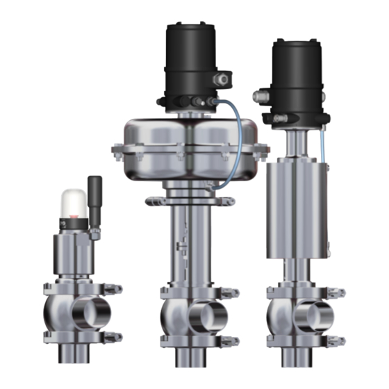
- Page 1 Operating Instructions Translation of the original Single Stage Control Valves Type 91xx P D F • a k • 0 2 / 0 9 / 2 0 2 2 ENGLISH...
- Page 2 . k i e s e l m a n n . d e • i n f o @ k i e s e l m a n n . d e Copyright: © KIESELMANN FLUID PROCESS GROUP...
-
Page 3: Table Of Contents
KIESELMANN GmbH Table of contents T a b l e o f c o n t e n t s 1 General informations .............................. 4 Informations for your safety ............................... 4 Marking of security instructions............................ 4 General designated use .............................. 4 Personnel ..................................... -
Page 4: General Informations
We will be at your disposal also after expiration of the warranty. In addition, you will also find all necessary instructions and spare part data for maintenance in this instruction manual. If you don't want to carry out the maintenance by yourself, our KIESELMANN - service team will naturally be at your disposal. -
Page 5: Modifications, Spare Parts, Accessories
KIESELMANN GmbH | Operating Instructions General informations | 1 1.5 Modifications, spare parts, accessories Unauthorized modifications, additions or conversions which affect the safety of the fitting are not permitted. Safety devices must not be bypassed, removed or made inactive. Only use original spare parts and accessories recommended by the manufacturer. -
Page 6: Safety Instructions
2 | Safety instructions Operating Instructions | KIESELMANN GmbH 2 S a f e t y i n s t r u c t i o n s 2.1 Intended use The control valve is used for the regulation of media in the food and beverage industry, in pharma- ceutical and chemical engineering, as well as in bio-engineering. - Page 7 KIESELMANN GmbH | Operating Instructions Safety instructions | 2 CAUTION When mounting the clamps, the max. torque must not be exceeded. (see technical data) CAUTION To avoid air leaking, only use pneumatic connection parts that have an O-ring seal facing the even surface.
-
Page 8: Delivery, Transport And Storage
3 | Delivery, transport and storage Operating Instructions | KIESELMANN GmbH 3 D e l i v e r y , t r a n s p o r t a n d s t o r a g e 3.1 Delivery... -
Page 9: Specification | 4
KIESELMANN GmbH | Operating Instructions Specification | 4 4 S p e c i f i c a t i o n 4.1 Modular system control systems positioner Guth DigiPos Bürkert Type 869x Bürkert Type 879x Samson Type 3730-X drive systems Manual drive pneum. -
Page 10: Function And Operation
5 F u n c t i o n a n d o p e r a t i o n 5.1 Description of function The control valve is based on the KIESELMANN AI DS technology. Media with a KVS -values 0,1 m³/ h to 160 m³/h can be regulated through the interchangeable seat concept. -
Page 11: Valve Basic Position
KIESELMANN GmbH | Operating Instructions Function and operation | 5 5.2 Valve basic position: Basic positon: Valve closed Valve open Kind of actuation: Normally closed (NC) Normally open (NO) Type: 911x Angle valve Section A - B closed Section A - B opened... -
Page 12: Commissioning, Service And Maintenance
6 | Commissioning, service and maintenance Operating Instructions | KIESELMANN GmbH 6 C o m m i s s i o n i n g , s e r v i c e a n d m a i n t e n a n c e 6.1 Commissioning... -
Page 13: Service
KIESELMANN GmbH | Operating Instructions Commissioning, service and maintenance | 6 6.2 Service RECOMMENDATION Replacement of seals To achieve optimal maintenance cycles, the following points must be observed! – When replacement of seals, all product-contacting seals should be replaced. –... -
Page 14: Technical Data
7 | Technical data Operating Instructions | KIESELMANN GmbH 7 T e c h n i c a l d a t a 7.1 Control valve Type 91xx Model control valve • elastomer sealing at the regulation cone (Elastomer / Elastomer) •... -
Page 15: Identification
KIESELMANN GmbH | Operating Instructions Technical data | 7 7.2 Identification Standards Manufacturer Logo 0036 EN ISO 4126-1 Date Order number Material Order No.: xxxxxxxx / x MM/JJJJ Item number Serial No.: xxxxxxxxxx-xxxx AISI xxxx Operating temperature DN xxx Ts -xx°C/+xxx°C... -
Page 16: Kv - Value
7 | Technical data Operating Instructions | KIESELMANN GmbH 7.4 KV - value -value, Valve size & Actuator size Pneumatic actuator Piston actuator Diaphragm actuator Valve size H104 H129 H167 H190 H230 Control air pressure [bar] Seat-Ø Stroke Adm. Operating Pressure [bar]... -
Page 17: Disassembly And Assembly | 8
KIESELMANN GmbH | Operating Instructions Disassembly and assembly | 8 8 D i s a s s e m b l y a n d a s s e m b l y 8.1 Disassembly Mounting tools Pos. Figure Designation... -
Page 18: Removing Wearing Parts - Valve With Manual Actuator
8 | Disassembly and assembly Operating Instructions | KIESELMANN GmbH 8.1.1 Removing wearing parts - Valve with manual actuator Dismount the valve insert • Unscrew the clamp coupling (VK). • Dismount the valve insert (VE) out of the housing (VG). - Page 19 KIESELMANN GmbH | Operating Instructions Disassembly and assembly | 8 Assembly piston / control cone for valves ≤ DN 25 • Unscrew the piston (1) respectively the flow ≤ DN25 cone (Rkm) with a pin wrench (T10). T10 Rkm • Hold with a punch (T35) at the bore (B2).
- Page 20 8 | Disassembly and assembly Operating Instructions | KIESELMANN GmbH Assembly seal (D1) • Clamp the cone (Rk) in a soft jawed vice. Un- screw the screw (Rk1). Remove piston (1) and dismantle O-ring (D1). Figure 7 NOTICE The bearing bush (3) do not need to be removed for a product-contacted seal change. The posi- tions are not included in the seal set.
-
Page 21: Removing Wearing Parts - Valve With Manual Actuator
KIESELMANN GmbH | Operating Instructions Disassembly and assembly | 8 8.1.2 Removing wearing parts - Valve with manual actuator Remove the valve insert (NC) • Connect compressed air to air supply (LA2). The piston (1) retracts. • Unscrew the locking clip (VK). - Page 22 8 | Disassembly and assembly Operating Instructions | KIESELMANN GmbH Assembly piston / control cone for valves ≤ DN 25 • Unscrew the piston (1) respectively the flow ≤ DN25 cone (Rkm) from the spindle (6) with a pin wrench (T10).
- Page 23 KIESELMANN GmbH | Operating Instructions Disassembly and assembly | 8 • Remove the distance (8), O-rings (D4) and (D5). Figure 7 NOTICE The distance (8) is fitted only with metric valves. The bearing bushes (3) and (5) and the O-rings (D4) and (D5) do not need to be removed for a product-contacted seal change.
-
Page 24: Removing Wearing Parts - Valve With Diaphragm Actuator
8 | Disassembly and assembly Operating Instructions | KIESELMANN GmbH 8.1.3 Removing wearing parts - Valve with diaphragm actuator Remove the valve insert (NC) • Connect compressed air to air supply (LA2). The piston (1) retracts. • Unscrew the locking clip (VK). - Page 25 KIESELMANN GmbH | Operating Instructions Disassembly and assembly | 8 Assembly piston / control cone for valves ≤ DN 25 • So that the bore (B1) will be visible, first dis- ≤ DN25 mantle the insert (2). • Unscrew the piston (1) respectively the flow Ø5...
-
Page 26: Removing Interchangeable Seat
8 | Disassembly and assembly Operating Instructions | KIESELMANN GmbH • Dismount seal (D3). Figure 7 NOTICE The bearing bush (3) do not need to be removed for a product-contacted seal change. The posi- tions are not included in the seal set. If they are worn,please order them (see wearing parts kit). -
Page 27: Assembly
KIESELMANN GmbH | Operating Instructions Disassembly and assembly | 8 8.2 Assembly • Assemble in reverse order. • Before installation, thoroughly clean and slightly lubricate mounting areas and running sur- faces. • Check the function according to the specified performance data in the operating state. -
Page 28: Mounting Kit For Positioner
9 | Mounting kit for positioner Operating Instructions | KIESELMANN GmbH 9 M o u n t i n g k i t f o r p o s i t i o n e r 9.1 Bürkert positioner Type 8692, 8694... - Page 29 KIESELMANN GmbH | Operating Instructions Mounting kit for positioner | 9 Assembly • Assemble in reverse order. • Before installation, thoroughly clean and slightly lubricate mounting areas and running sur- faces. • Check the function according to the specified performance data in the operating state.
-
Page 30: Guth Positioner Digipos
9 | Mounting kit for positioner Operating Instructions | KIESELMANN GmbH 9.2 Guth Positioner DIGIPOS Disassembly NOTICE Before reaching into the device or the equipment, please note the operating instructions and the safety instructions for the Guth DigiPos Positioner. (Operating Instructions for Guth DigiPos Type BA_DP_022012) - Page 31 KIESELMANN GmbH | Operating Instructions Mounting kit for positioner | 9 Assembly • Assemble in reverse order. • Before installation, thoroughly clean and slightly lubricate mounting areas and running sur- faces. • Check the function according to the specified performance data in the operating state.
-
Page 32: Drawings And Dimensions
10 | Drawings and dimensions Operating Instructions | KIESELMANN GmbH 1 0 D r a w i n g s a n d d i m e n s i o n s 10.1 Drawings Valve structure Manual operation Pneumatic operation... - Page 33 KIESELMANN GmbH | Operating Instructions Drawings and dimensions | 10 Valve inserts • 1 = Piston Manual operation with crank handle • 2 = Insert • 3 = Plain bearing DS 1 DS 2 • 4 = Lantern VS 1 •...
- Page 34 10 | Drawings and dimensions Operating Instructions | KIESELMANN GmbH Pneumatic operation with diaphragm actuator • 1 = Piston • 2 = Insert DS 1 • 3 = Bearing bush DS 2 • 4 = Lantern VS 3 • 5 = -- •...
-
Page 35: Dimensions
KIESELMANN GmbH | Operating Instructions Drawings and dimensions | 10 10.2 Dimensions Wrench size (SW) DN = Nominal diameter DN 25 DN 40 DN 50 DN 65 DN 80 DN 100 DN 125 OD = Outside diameter OD 1 OD 1"... - Page 36 10 | Drawings and dimensions Operating Instructions | KIESELMANN GmbH Dimensions DN / OD Drive DN 20 Ø 23 x 1,5 H104 Ø 104 ~550 DN 25 Ø 29 x 1,5 Manual ~224 H104 Ø 104 ~560 OD 1 Ø25.4x1.25 H129 Ø...
-
Page 37: Wearing Parts | 11
KIESELMANN GmbH | Operating Instructions Wearing parts | 11 1 1 W e a r i n g p a r t s 11.1 Overview - Seal and wearing parts kits Wear parts kit Material: Designation - in product contact... - Page 38 11 | Wearing parts Operating Instructions | KIESELMANN GmbH Wearing part set DS1 (elastomeric sealing) Seat-Ø Wear parts kit Wear parts kit Wear parts kit Value DS 1a EPDM DS 1b HNBR DS 1c FKM ø 5 9110 010 200-K990...
- Page 39 KIESELMANN GmbH | Operating Instructions Wearing parts | 11 Wearing part set DS2 (metallic sealing) Seat-Ø Wear parts kit Wear parts kit Wear parts kit Value DS 2a EPDM DS 2b HNBR DS 2c FKM ø 6 9110 010 400-M990...
- Page 40 11 | Wearing parts Operating Instructions | KIESELMANN GmbH Wearing part set - Actuator Kind of actuation Wear parts kit Wear parts kit Wear parts kit Actuator 1 Actuator 2 Actuator 3 manual actuator 9111 000 000-991 Linear actuator ø104 9112 000 001-991 ø129...
-
Page 41: Classification | 12
KIESELMANN GmbH | Operating Instructions Classification | 12 1 2 C l a s s i f i c a t i o n 12.1 Structure of Order Number Feedback unit/positioner Variations of actuation Seal Separator Connection Valve outlet Connection Valve inlet... -
Page 42: Appendix
13 | Appendix Operating Instructions | KIESELMANN GmbH 1 3 A p p e n d i x 13.1 Declaration of incorporation Declaration of incorporation Translation of the original Manufacturer / authorised representative: KIESELMANN GmbH Paul-Kieselmann-Str. 4-10 75438 Knittlingen Germany...
Need help?
Do you have a question about the 91 Series and is the answer not in the manual?
Questions and answers