Cleco mPro400GC Installation Manual
Hide thumbs
Also See for mPro400GC:
- Programming manual (68 pages) ,
- Hardware description (16 pages) ,
- Quick setup manual (21 pages)

Subscribe to Our Youtube Channel
Related Manuals for Cleco mPro400GC


Summary of Contents for Cleco mPro400GC
- Page 1 Installation Manual P2434JH-EN 2022-07 mPro400GC(D) Integrating mPro400GC and mPro400GCD For additional product information visit our website at www.ClecoTools.com...
- Page 2 Apex Tool Group reserves the right to modify, supplement, or improve this document or the product with- out prior notice. Trademark Cleco Production Tools is a registered trademark of Apex Brands, Inc. Apex Tool Group 670 Industrial Drive Lexington, SC 29072...
-
Page 3: Table Of Contents
Install Primary/Master Controller with Existing Secondary Controllers ...... 7 Install Primary/Master Controller with New Secondary Controllers ......9 Install Primary/Master Controller with Secondary Controllers mPro400GC ....10 Install Primary/Master Controller with Secondary Controllers mPro400GCD.....12 Install Primary/Master Controller with Two Types of Secondary Controllers .....13 Install Primary/Master Controller with Secondary Controllers and Stack Lights ..15... -
Page 4: About This Document
About this document About this document This document is intended for all persons who replaces mPro400GC-P/-M by mPro400GCD-P/-M. It contains information • on installation • on configuration and function. The original language of this document is English. Observe the safety instructions listed in the respective hardware descriptions! -
Page 5: Distinction Of Controller Types
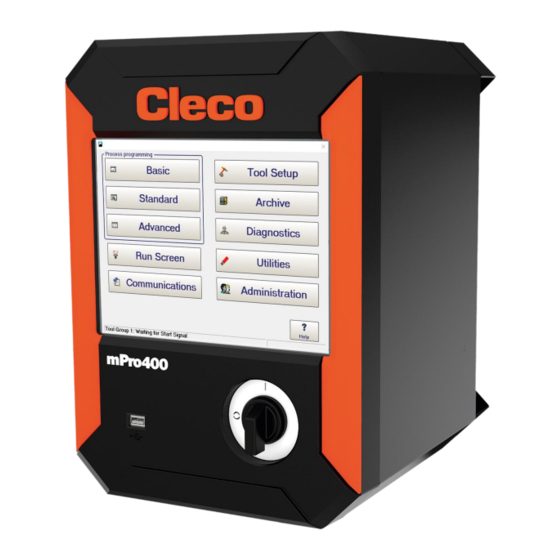
Distinction of Controller Types Distinction of Controller Types There are two types of Global Controller: • mPro400GC: only for analog tools • mPro400GCD: for analog and digital tools For controllers produced after November 2017, the software automatically recognizes the controller type. If the software does not automatically recognize the controller type, the type has to be confirmed manually. -
Page 6: Mpro400Gc Replaced By Mpro400Gcd
Replaced by mPro400GCD mPro400GC Replaced by mPro400GCD If mPro400GC-P/-M is replaced by mPro400GCD-P/-M, certain things need to be considered. Below are various scenarios and procedures for exchanging controller types. Primary/Master Controller Scenario • mPro400GC-P/-M is replaced by mPro400GCD-P/-M •... -
Page 7: Install Primary/Master Controller With Existing Secondary Controllers
Blue LED Output Confirm the change with <OK> and <Accept>. Install Primary/Master Controller with Existing Secondary Controllers Scenario • mPro400GC-P/-M is replaced by mPro400GCD-P/-M • Existing mPro400GC-S used Old system layout New system layout Abb. 3-3: Primary/Master controller mPro400GC Abb. 3-4: Primary/Master controller mPro400GCD... - Page 8 Ensure that the current version of the operating system is used. The operating system has to be 2.7 or newer. mPro400GCD-P/-M: output X22 mPro400GC-S: input X31 Use the System Bus cable to connect additional mPro400GC-S to the previous mPro400GC-S if nec- essary. Use following inputs and outputs: Previous mPro400GC-S: output X32 Following mPro400GC-S: input X31 Connect the System Bus terminator to X32 at the last mPro400GC-S.
-
Page 9: Install Primary/Master Controller With New Secondary Controllers
192 168 245 200 Subnet Mask 255 255 255 0 Set up mPro400GC-P/-M Use the RJ45 to TSnet cable to connect mPro400GC-P/-M and mPro400GCD-S(H). See documenta- tion P2174HW. Use following inputs and outputs: mPro400GC-P/-M: output X1 mPro400GCD-S(H): input X22 (TSnet in) The TSnet cable may not be connected to the infrastructure network. -
Page 10: Install Primary/Master Controller With Secondary Controllers Mpro400Gc
Select tool group. It is possible to select up to 16 tool groups. Name Assign a name to the Secondary. Type Select Secondary. Confirm with <OK>. Install Primary/Master Controller with Secondary Controllers mPro400GC Scenario • mPro400GC-P/-M is replaced by mPro400GCD-P/-M • No Secondary controllers connected... - Page 11 Ensure that the current version of the operating system is used. The operating system has to be 2.7 or newer. mPro400GCD-P/-M: output X22 mPro400GC-S: input X31 Use the System Bus cable to connect additional mPro400GC-S to the previous mPro400GC-S if nec- essary. Use following inputs and outputs: Previous mPro400GC-S: output X32 Following mPro400GC-S: input X31 Connect the System Bus terminator to X32 at the last mPro400GC-S.
-
Page 12: Install Primary/Master Controller With Secondary Controllers Mpro400Gcd
Replaced by mPro400GCD Signal Input/Output Bit PM_DIDO Bit TM_DIDO Function button 2 Input Status (Yellow LED) Output Tool OK 1 (Green LED) Output Tool NOK 1 (Red LED) Output Blue LED Output Confirm the change with <OK> and <Accept>. -
Page 13: Install Primary/Master Controller With Two Types Of Secondary Controllers
Confirm with <OK>. Install Primary/Master Controller with Two Types of Secondary Controllers Scenario • mPro400GCD-P/-M • mPro400GC-S and mPro400GCD-S(H) are added Old system layout New system layout Fig. 3-9: Primary/Master controller mPro400GCD with Secondary control- ler mPro400GC and mPro400GCD Apex Tool Group... - Page 14 X22 mPro400GC-S: input X31 The TSnet cable may not be connected to the infrastructure network. Use the System Bus cable to connect additional mPro400GC-S to the previous mPro400GC-S if nec- essary. Use following inputs and outputs: Previous mPro400GC-S: output X32 Following mPro400GC-S: input X31 Connect the System Bus terminator to X32 at the las t mPro400GC-S.
-
Page 15: Install Primary/Master Controller With Secondary Controllers And Stack Lights
Name Assign a name to the Secondary. Type Select Secondary. Confirm with <OK>. Install Primary/Master Controller with Secondary Controllers and Stack Lights In combination with stack lights, mPro400GC and mPro400GCD controllers cannot be mixed. 3.7.1 mPro400GC Scenario • mPro400GCD-P/-M •... - Page 16 Use the System Bus cable to connect mPro400GC-P/-M and the first stack light. Use following inputs and outputs: mPro400GC-P/-M: output X21 Stack light: input ARCNet in Use the System Bus cable to connect mPro400GC-S to the stack light. Use following inputs and out- puts: Stack light: output ARCNet out mPro400GC-S: input X31 Use the System Bus cable to connect additional mPro400GC-S or stack lights.
-
Page 17: Mpro400Gcd
Replaced by mPro400GCD Item Setting ► Select A-IOS. ► Enter ARCNet address. ► Select the desired signal. ► Enter the bit. The inputs are from bit 0 - 7, the outputs are from bit 8 - 15. For more information see ON / OUTPUTS A- OK BRIDGE in the supplied BUILDING PLAN of the stack lights. - Page 18 Replaced by mPro400GCD Use the System Bus cable to connect additional stack lights. Connect the System Bus terminator to X32 at the last mPro400GC-S. Connect mPro400GCD-P/-M and mPro400GCD-S(H). See chapter see chapter 3.5 Install Pri- mary/Master Controller with Secondary Controllers mPro400GCD, page 12.
- Page 20 POWER TOOLS SALES & SERVICE CENTERS Please note that all locations may not service all products. Contact the nearest Cleco® Sales & Service Center for the appropriate facility to handle your service requirements. Sales Center Service Center NORTH AMERICA | SOUTH AMERICA...
Need help?
Do you have a question about the mPro400GC and is the answer not in the manual?
Questions and answers