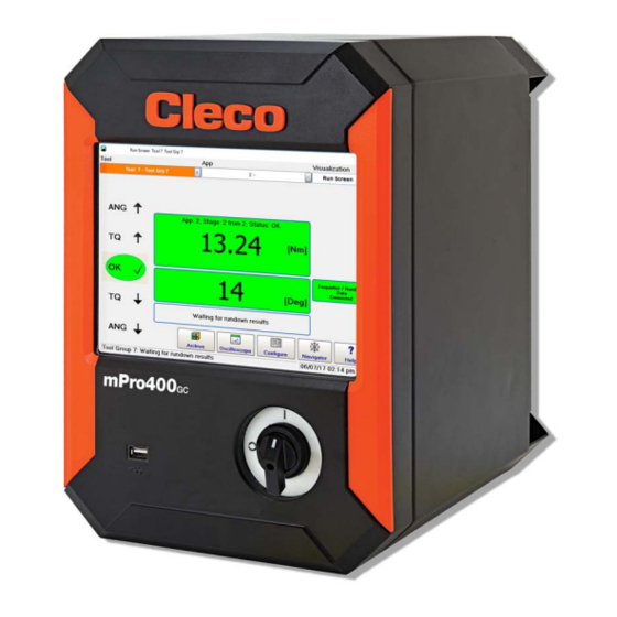
Cleco mPro400GCD-P Hardware Description
Global nutrunner controller primary
Hide thumbs
Also See for mPro400GCD-P:
- Hardware description (48 pages) ,
- Manual (48 pages) ,
- Quick installation manual (14 pages)

Related Manuals for Cleco mPro400GCD-P


Summary of Contents for Cleco mPro400GCD-P
- Page 1 Hardware description P2300HW-EN 2018-01 mPro400GCD-P Global Nutrunner Controller Primary For additional product information visit our website at http://www.ClecoTools.com...
- Page 2 Disclaimer Apex Tool Group reserves the right to modify, supplement, or improve this document or the product without prior notice. Trademark Cleco is a trademark of the Apex Tool Group Division. Apex Tool Group GmbH Industriestraße 1 73463 Westhausen Germany...
-
Page 3: Table Of Contents
P2300HW-EN 2018-01 Contents Notes on this Hardware-Description Safety General requirements....................4 Warnings and notes..................... 5 System-relevant safety instructions................6 Technical specifications Pin assignment Storage access Items delivered Installation Location considerations..................... 13 Mounting........................13 Prior to initial operation Series 30/50EAN....................... 14 Series 18/48EAE ....................... -
Page 4: Notes On This Hardware-Description
Symbols in the text Intended use Denotes menu options, e.g.,Diagnostics Italic The product is a part of the Cleco Production Tools tighten- > Denotes the selection of a menu option from ing system and is intended exclusively for industrial use in a menu, e.g., File >... -
Page 5: Warnings And Notes
P2300HW-EN Operator training WARNING! A symbol combined with the word WARN- The tightening system may only be put into operation, ING indicates a hazard with a medium adjusted and tested by qualified and trained personnel. level of risk which, if not avoided, could The personnel must be instructed by qualified employees result in death or serious injury. -
Page 6: System-Relevant Safety Instructions
System-relevant safety For 115 VAC cables with a larger cross-section, use Order No. 541683-01. instructions Prior to initial operation We do not claim that these safety instructions are com- plete. It is obligatory to follow national, state and local Only operate on a grounded power supply (TN system). - Page 7 At the repair rare cases. Possible reasons: Remote control of diagnostic functions, bit dump in the memory of the controller. Send the complete nutrunner controller for repair to Mechanical hazards such as jars/jolts due to counter your Sales & Service Center. torques;...
-
Page 8: Technical Specifications
P2300HW-EN 2018-01 Technical specifications Ambient conditions Features Data Operation site Indoors Ambient temperature 0...45 °C Storage temperature -20...70 °C Type of cooling Convection (self-cooling) Relative humidity 10 – 90%, no condensation Working height Up to 2000 m (6,561.7 ft) above sea level Protection Class DIN EN 60529 IP42 Degree of contamination EN 61010... -
Page 9: Pin Assignment
P2300HW-EN 2018-01 Pin assignment X22 – ARCNET system bus All connections are short-circuit proof. The station controller has an integrated bus termination; X5, X6 – Serial port for additional devices therefore, no external termination is necessary. • All outputs provide RS232 conforming signals. Signal 8 pin M12 circular connector •... - Page 10 P2300HW-EN 2018-01 X9, X10 – Input/Output The required signal circuits are connected to these input/output connectors. The signal groups are not gal- vanically connected to the power supply; galvanic isolation is required. • 16 digital inputs/outputs, optically isolated for 24 V level/0.5 A •...
- Page 11 P2300HW-EN 2018-01 Signal X9 Signal X10 Name Name GND2 GND2 Common GND Common GND Output Output Output Output Output Output Output O0 (linking OK), e.g. Output Input I3 (tool start), e.g. Input Input Input Input Input Input Input Output O0-O3 common Output O4-O7 common +24 V2 +24 V2...
-
Page 12: Storage Access
Only pull out or plug in the CF card when the supply voltage is switched off. Otherwise, serious system TION! errors and data loss will result. Items delivered Check delivery for transit damage and ensure that all items have been supplied: • Global Nutrunner Controller mPro400GCD-P • EC Declaration of Conformity • Hardware description • SP-1500 •... -
Page 13: Installation
P2300HW-EN 2018-01 Installation Software is already installed on the controller. The minimum settings for your bolt connections must be car- ried out by a qualified person with the controller or a PC in order to start fastening work. Location considerations Each controller is mainly used as a control and monitoring unit for one or more tools at a workstation. -
Page 14: Prior To Initial Operation
P2300HW-EN 2018-01 Prior to initial operation The power is supplied to the tool via the networking with the controller. It is not possible to operate the Series 30/50EAN tools on connector X24 and the Series 18/48EAE tools on connector X25. Series 30/50EAN Cable connection with the tool 1. -
Page 15: Series 18/48Eae
P2300HW-EN 2018-01 Series 18/48EAE Cable connection with the tool 1. Align the groove on the tool cable with the start Start switch switch on the tool handle. 2. Insert the tool cable into the handle of the nut- runner and tighten by turning clockwise by Groove hand. -
Page 16: Connecting The Controller To The Power Source
P2300HW-EN 2018-01 Connecting the controller to the power source 1. Ensure alternating voltage of 100 VAC or 240 VAC. 2. Connect the power cable to the X23 connector. 3. To secure the connector, install the plug lock- ing mechanism (Order No. 544004-1) from the bottom on the cable. -
Page 17: System
P2300HW-EN 2018-01 System CF-card mPro400GCD-P Main switch Pos. Product Possible connections Serie 30EAN…/50EAN… 1× Serie 18EAE…/48EAE… 1× Serie 17BP…/47BA… 15× Serie 18EAE…/48EAE… + mPro400GC-S 15× Serie 30EAN…/50EAN…+ mPro400GCD-S 15× Access Point ArcNet-Kabel TSNet-Kabel... -
Page 18: Connections
P2300HW-EN 2018-01 Connections Abb. 10-1: Connection positions Designation Designation Ethernet RJ45 10/100 BASE-T Connector #1 I/O Connector Ethernet RJ45 10/100 BASE-T Connector #2 I/O Connector USB V2.0 Port #1 System Bus Connector TSnet USB V2.0 Port #2 System Bus Connector ArcNet Serial RS232-1 Connector #1 Power supply connection Serial RS232-2 Connector #2... -
Page 19: Dimensions
P2300HW-EN 2018-01 Dimensions 327,66 mm (12,900" ) 276,23 mm 266,7 mm (10.875" ) (10,500" ) 381,0 mm (15.000" ) 288,04 mm (11.340") 336,30 mm (13.240" ) - Page 20 P2300HW-EN 2018-01 Mounting plate Possible receiving points for fixing the mounting plate of the wall 197 mm (7.756") 90 mm (3.543") 10× 6,8 mm 23,8 mm (0.268") (0.937" ) 10× 8 mm (0.315") 32,5 mm (1.28" ) 10× 14,4 mm (0.567") 232,5 mm (9.154")
- Page 22 POWER TOOLS SALES & SERVICE CENTERS Please note that all locations may not service all products. Contact the nearest Cleco ® Sales & Service Center for the appropriate facility to handle your service requirements. Sales Center Service Center NORTH AMERICA | SOUTH AMERICA...
Need help?
Do you have a question about the mPro400GCD-P and is the answer not in the manual?
Questions and answers