
Related Manuals for Cleco mPro400GCD-M


Summary of Contents for Cleco mPro400GCD-M
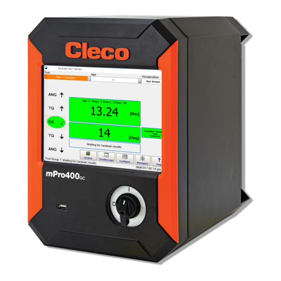
- Page 1 Hardware Description P2309HW 2019-08 mPro400GCD-M Global Controller Master For additional product information visit our website at www.ClecoTools.com...
- Page 2 Disclaimer The Apex Tool Group reserves the right to modify, supplement, or improve this document or the product without prior notice. Trademark Cleco is a registered trademark of Apex Brands, Inc. Apex Tool Group GmbH Industriestraße 1 73463 Westhausen Germany...
-
Page 3: Table Of Contents
Contents Notes on this Description ..............5 Safety ....................5 Product description................9 Technical Specifications ............... 9 Pin Assignment................... 10 Storage Access .................. 12 Items Delivered .................. 12 Zu dieser Beschreibung ..............13 Sicherheit ................... 13 Produktbeschreibung ................. 17 Technische Daten ................17 Steckerbelegung ................ - Page 4 À propos de cette description du matériel........... 29 Sécurité ....................29 Description du produit ................. 33 Caractéristiques techniques..............33 Disposition des connecteurs ............... 34 Accès à la mémoire, mémoire portable ..........36 Volume de livraison ................36 Informacje dotyczące tego opisu ............37 Bezpieczeństwo ..................
-
Page 5: Notes On This Description
V1.8.0 S168677 mProRemote – Interface software between an The controller is a part of the Cleco Production Tools Tight- external computer and controller ening System and is intended exclusively for industrial use in fastening processes. Only use the controller under the... - Page 6 2.5 Personal Protective Equipment 2.7 Symbols on the Product (PPE) Be sure to understand the meaning of each symbol below prior to installation, operation or maintenance service. When working with rotating parts, it is not permitted to wear gloves. Recommendation: Freely rotating u-GUARD pro- Electrical voltage tected fastening tools are available from APEX.
- Page 7 Always turn off the controller before connecting power The necessity of an emergency stop and its execution and tool cables, cleaning or removal from operation. is the responsibility of the user and his risk analysis! Do not operate the tightening system if the housing, ...
- Page 8 Do not use a high pressure or abrasive cleaner. Repair Repairs to the equipment are not permitted. Send the controller to a Authorized Cleco Production Tools Sales & Service Centers. Disposal Components of the tightening system may present poten- tial risks the environment. The tightening system contains components that can be recycled, as well as components that have specific disposal requirements.
-
Page 9: Product Description
1. Note the derating. See the System Handbook NeoTek Weight Power Supply Model Weight* Features Data Supply Voltage, 100–240 VAC ± 10% mPro400GCD-M 21.3 Single Phase Rated Supply Current 0.2 A Frequency 50/60 Hz Peak Current 2.5 A Rated Power 120 VA max. -
Page 10: Pin Assignment
Pin Assignment Signal 8 Pin M12 Circular Connector A-Coded This chapter describes the Cleco Production Tools specific N.C. connectors. Standard plugs are not considered. All con- DATA-B nections are short-circuit proof. X5, X6 – Serial port for additional devices +5 VDC •... - Page 11 Connectors – Internal power supply Example: Signal X9 Signal X10 Name Name Supply GND Int. Supply GND Int. Supply GND I/O Supply GND I/O Output Output Output Output Output Output Output Output Input Input Input Input Input Input Input Input Supply +24 V O Supply +24 V O Supply +24 V Int.
-
Page 12: Storage Access
Storage Access 4× S909344 M3×5 DIN912 Abb. 6-1: Storage Pos. Name Function CF Card Necessary for the operating system and archiving files/applications. Included with controller. (Compact Flash) SD Card, Optional Function is software-dependent: software update, save/load parameters, data archive files. Note Only remove or plug in the CF card when the supply voltage is switched off. -
Page 13: Zu Dieser Beschreibung
Verfügung. S168677 mPro-Remote Schnittstelle-Software zwischen externem Computer und Steuerung 2.2 Bestimmungsgemäße Verwendung Das Produkt ist Teil des Cleco Production Tools Weiterführende Dokumente Schraubsystems und ist ausschließlich für den industriellen Ident-Nr. Einsatz in Schraubprozessen bestimmt. Steuerung unter folgenden Bedingungen verwenden: P1730E Verfahrensbeschreibung •... - Page 14 2.5 Persönliche Schutzausrüstung 2.7 Symbole auf dem Produkt Verletzungsgefahr durch Aufwickeln und Erfassen Beim Arbeiten mit rotierenden Teilen ist das Tragen Elektrische Spannung von Handschuhen verboten. Empfehlung: Frei drehende u-GUARD geschützte Schraubwerkzeuge von APEX. Enganliegende Kleidung tragen. Sicherheitsschuhe tragen. CE konform ...
- Page 15 Vor Anschluss von Netz- und Werkzeugkabel, beim Die Notwendigkeit eines Not-Halts und dessen Aus- Umrüsten, einer Reinigung oder einer Außerbetrieb- führung obliegt dem Anwender und seiner Risikoana- nahme die Steuerung abschalten. lyse! Schraubsystem nicht betreiben, falls Gehäuse, Kabel ...
- Page 16 Keinen Hochdruckreiniger verwenden. Bei der Reparatur Reparaturen am Gerät sind unzulässig. Die Steuerung an ein autorisiertes Cleco Production Tools Sales & Service Centers schi- cken. Bei der Entsorgung Komponenten des Schraubsystems stellen mögliche Gefahren für Gesundheit und Umwelt dar. Das Schraubsystem enthält Komponenten, die recycelt werden...
-
Page 17: Produktbeschreibung
Eingaben DIN EN 60068-2-27 (Human Machine-Interface) Vibration max. 59.6–160 Hz: 2 G Gewicht DIN EN 60068-2-5 1. Derating beachten. Siehe Systemhandbuch Modell Gewicht* Spannungsversorgung mPro400GCD-M 21.3 Merkmale Daten Versorgungsspannung, 100–240 VAC ±10 % einphasig Versorgungsnennstrom 0,2 A Frequenz 50/60 Hz... -
Page 18: Steckerbelegung
Steckerbelegung X22 – Systembus ARCNET Integrierter Busabschluss. Kein externer Abschluss not- Diese Kapitel beschreibt die Cleco Production Tools spezi- wendig. fischen Stecker. Standard-Stecker werden nicht berück- Signal 8 pol. M12 Rundsteckverbinder sichtigt. Alle Anschlüsse sind kurzschlussfest. A-codiert X5, X6 – Zusatzgeräte N.C. - Page 19 Anschlüsse – Interne Spannungsversorgung Beispiel: Signal X9 Signal X10 Bezeichnung Bezeichnung Versorgung GND Int. Versorgung GND Int. Versorgung GND I/O Versorgung GND I/O Ausgang O3 Ausgang O7 Ausgang O2 Ausgang O6 Ausgang O1 Ausgang O5 Ausgang O0 Ausgang O4 Eingang I3 Eingang I7 Eingang I2 Eingang I6...
-
Page 20: Speicherzugänge
Speicherzugänge 4× S909344 M3×5 DIN912 Abb. 6-1: Position der Anschlüsse Pos. Bezeichnung Funktion CF-Karte (Compact Flash) Betriebsystem, Archivdateien und Anwendungen. Im Lieferumfang enthalten. SD-Karte, optional Funktion ist Software-abhängig: Software-Update, Parameter speichern/laden, Datenarchivdateien... Hinweis Nur bei ausgeschalter Versorgungsspannung die CF-Karte ziehen oder stecken. Schwere Systemfehler und Datenverlust sind bei Nichtbeachtung die Folge. -
Page 21: Acerca De Esta Descripción Del Hardware
Software de interfaz entre la computadora externa y el controlador Este producto forma parte del sistema de apriete Cleco Production Tools y está exclusivamente destinado Otros documentos de interés para la aplicación industrial en procesos de atornillado. Uti- lice el controlador en las siguientes condiciones: N.º... - Page 22 2.7 Símbolos en el producto El controlador ha sido preconfigurado por Apex Tool Group. La adaptación del controlador a unos Asegúrese de haber entendido su significado antes de utili- requisitos concretos solo puede llevarla a cabo una per- zar el producto: sona calificada .
- Page 23 Desconecte el controlador antes de conectar el cable La necesidad de una parada de emergencia y su eje- de alimentación, cuando esté reequipando, limpiando cución es responsabilidad del usuario y del análisis de o poniendo fuera de servicio el controlador. riesgos que este realice.
- Page 24 No utilice limpiadoras de alta presión. Durante la reparación No está permitido realizar reparaciones en el equipo. Envíe el controlador a un Cleco Production Tools Sales & Service Center autorizado. Durante el desecho Los componentes del sistema de apriete conllevan riesgos potenciales para la salud y el medio ambiente.
-
Page 25: Descripción Del Producto
Vibración máx. 59.6–160 Hz: 2 G Peso DIN EN 60068-2-5 1. Tome en cuenta la reducción. Vea el Manual del sis- Modelo Peso* tema mPro400GCD-M 21.3 Alimentación eléctrica Características Datos Tensión de alimentación, 100–240 VCA ±10 % monofásica Corriente nominal de ali- 0.2 A... -
Page 26: Asignación De Enchufes
Terminación de bus integrada. No se necesita ninguna Este capítulo describe el conector específico de conexión externa. Cleco Production Tools. No se consideran los conectores Señal Conexión de enchufe redondo de estándar. Todas las conexiones son a prueba de cortocir- 8 pol. - Page 27 Conexiones: suministro de tensión interno Ejemplo: Señal X9 Señal X10 Designación Designación Suministro GND int. Suministro GND int. Suministro E/S GND Suministro E/S GND Salida Salida Salida Salida Salida Salida Salida Salida Entrada Entrada Entrada Entrada Entrada Entrada Entrada Entrada Suministro +24 V O Suministro +24 V O Suministro +24 V int.
-
Page 28: Acceso A Memoria
Acceso a memoria 4× S909344 M3×5 DIN912 Fig. 6-1: Posición de las conexiones Pos. Designación Función Tarjeta CF Sistema operativo, ficheros de archivo y aplicaciones. (Compact Flash) Incluida en el volumen del suministro. Tarjeta SD, opcional La función depende del software: actualización del software, guardar/cargar paráme- tros, ficheros de archivo de datos... -
Page 29: À Propos De Cette Description Du Matériel
Déclaration de conformité CE Le produit fait partie intégrante du système de mPro400GCD-M vissage Cleco Production Tools et est destiné exclusive- ment pour les applications industrielles dans les processus de vissage. Utiliser la commande dans les conditions sui- Symboles dans le texte... - Page 30 2.4 Formation du personnel Remarque Ce système de vissage doit être mis en service, réglé et Un symbole en relation avec le mot Re- contrôlé uniquement par des personnes qualifiées et for- marque caractérise une situation poten- mées. Le personnel doit être instruit par des collaborateurs tiellement dommageable qui, si elle n'est qualifiés d'Apex Tool Group/Apex Tool Group‚...
- Page 31 N'apportez aucune modification au contrôleur, aux dis- Utilisez le câble d'alimentation fourni. Lors du rempla- positifs de protection ou aux accessoires sans l'autori- cement, utilisez un câble d'alimentation approprié. sation écrite préalable d'Apex Tool Group. Pour les câbles 115 V c.a. de section supérieure, utili- ...
- Page 32 Les réparations de l'équipement ne sont pas permises. rage inattendu de la machine peut se produire. Les raisons Envoyez le contrôleur à un Cleco Production Tools possibles peuvent inclure, sans se limiter : commande à Centre de distribution et de maintenance autorisé.
-
Page 33: Description Du Produit
1. Tenir compte du déclassement. Voir le manuel sys- entrées alphanumériques (Interface Homme tème Machine) Alimentation électrique Poids Caractéristiques Valeurs Modèle Poids Tension d'alimentation, 100–240 V CA ±10 %) monophasée mPro400GCD-M 21.3 Courant nominal d'alimenta- 0,2 A tion Fréquence 50/60 Hz Apex Tool Group P2309HW | 2019-08... -
Page 34: Disposition Des Connecteurs
Broche Signal 8 broches. M12 Connecteurs circulaires Ce chapitre décrit le connecteur spécifique à codé Cleco Production Tools. Les connecteurs standard ne sont N.C. pas considérés. Toutes les connexions sont résistantes au DATA-B court-circuit. X5, X6 – Appareils supplémentaires +5 VDC •... - Page 35 Connexions – Alimentation électrique interne Exemple: Signal X9 Signal X10 Broche E/S Désignation Broche E/S Désignation Alimentation GND Int. Alimentation GND Int. Alimentation GND I/O Alimentation GND I/O Sortie Sortie Sortie Sortie Sortie Sortie Sortie Sortie Entrée Entrée Entrée Entrée Entrée Entrée Entrée...
-
Page 36: Accès À La Mémoire, Mémoire Portable
à de sérieux risques d'erreurs système et de perte des données.. Volume de livraison Vérifier que la livraison ne présente aucun endommage- ment dû au transport et que le produit fourni est complet : • Commande mPro400GCD-M • Déclaration de conformité CE • La présente description du matériel •... -
Page 37: Informacje Dotyczące Tego Opisu
V1.8.0 przeznaczeniem S168677 mPro-Remote Produkt stanowi część systemu wkrętarskiego Interfejs programowy pomiędzy kompute- Cleco Production Tools i jest przeznaczony wyłącznie do rem zewnętrznym i systemem sterowania użytku przemysłowego podczas procesów wkrętarskich. Sterownik użytkować po spełnieniu następujących warun- Pozostałe dokumenty ków: •... - Page 38 2.4 Środki ochrony indywidualnej 2.6 Symbole umieszczone na produkcie Niebezpieczeństwo zranienia przez wciągnięcie Przy wykonywaniu prac przy obracających się czę- Napięcie elektryczne ściach noszenie rękawic jest zabronione. Zalecenie: zastosować narzędzia wkrętarskie swobod- nie obracające się w otulinie ochronnej u-GUARD firmy APEX.
- Page 39 Przed przyłączeniem kabla sieciowego lub narzędzia, Konieczność zastosowania urządzeń zatrzymania podczas przezbrajania, czyszczenia lub wyłączania z awaryjnego i ich dobór oraz analiza ryzyka należą do użytkowania wyłączyć układ sterowania. obowiązków użytkownika! Nie użytkować systemu wkrętarskiego w razie stwier- ...
- Page 40 Nie stosować myjek ciśnieniowych. Podczas naprawy Naprawy urządzenia są zabronione. Wysłać układ sterowania do autoryzowanego Cleco Production Tools Sales & Service Center. Podczas utylizacji Podzespoły systemu wkrętarskiego stwarzają potencjalne zagrożenia dla zdrowia i środowiska. System wkrętarski składa się z podzespołów, które można poddać ponow- nemu przetwarzaniu, oraz takich, które wymagają...
-
Page 41: Opis Produktu
Patrz podręcznik systemu Klawiatura wirtualna dla wpisów alfanumerycznych (Human Machine-Inter- Zasilanie elektryczne face) Cechy Dane Masa Napięcie zasilające, 100–240 V AC ±10% jednofazowe Model Ciężar* Znamionowy prąd zasilający 0,2 A Częstotliwość 50/60 Hz mPro400GCD-M 21.3 Apex Tool Group P2309HW | 2019-08... -
Page 42: Rozkład Wyprowadzeń
Rozkład wyprowadzeń X22 – magistral systemowa ARCNET Zintegrowany terminator magistrali. Brak konieczności sto- Ten rozdział opisuje wtyki stosowane przez Cleco Produc- sowania zewnętrznego terminatora. tion Tools. Nie uwzględniono wtyków standardowych. Styk Sygnał 8-stykowe gniazdo okrągłe M12 Wszystkie złącza są odporne na zwarcia. - Page 43 Przyłącza – wewnętrzne zasilanie Przykład: Sygnał X9 Sygnał X10 Styk Oznaczenie Styk Oznaczenie Zasilanie GND wew. Zasilanie GND wew. Zasilanie GND I/O Zasilanie GND I/O Wyjście Wyjście Wyjście Wyjście Wyjście Wyjście Wyjście Wyjście Wejście Wejście Wejście Wejście Wejście Wejście Wejście Wejście Zasilanie +24 V zew.
-
Page 44: Dostępy Do Pamięci
Dostępy do pamięci 4× ((Bramka komu- nikacji szeregowej- il. 6-1: Pozycja przyłączy Poz. Oznaczenie Funkcja Karta CF (Compact System operacyjny, pliki archiwum i aplikacje. Flash) W zakresie dostawy. Karta SD, opcjonalna Funkcja jest zależna od oprogramowania: aktualizacja oprogramowania, zapisywa- nie/wczytywanie parametrów, pliki archiwum danych. Informacja Kartę... -
Page 45: System
System mPro400GCD-M CF-card Main switch Pos. Product Possible connections Serie 17BP…/47BA… 16× Serie 30E×N…/50E×N… + mPro400GCD-S 16× Serie 18E×E…/48E×E… + mPro400GC-S 16× Access Point TSNet-Kabel ArcNet-Kabel Apex Tool Group P2309HW | 2019-08... -
Page 46: Connections
Connections Abb. 9-1: Connections positions Designation Designation Ethernet RJ45 10/100 BASE-T Connector #1 I/O Connector Ethernet RJ45 10/100 BASE-T Connector #2 I/O Connector USB V2.0 Port #1 System Bus Connector TSnet USB V2.0 Port #2 System Bus Connector ArcNet Serial RS232-1 Connector #1 Power supply connection Serial RS232-2 Connector #2 Anybus CC –... -
Page 47: Dimensions
Dimensions mPro400GCD-M 327,66 mm (12,900" ) 276,23 mm 266,7 mm (10,500" ) (10.875" ) 381,0 mm (15.000" ) 288,04 mm (11.340") 336,30 mm (13.240" ) Apex Tool Group P2309HW | 2019-08... - Page 48 POWER TOOLS SALES & SERVICE CENTERS Please note that all locations may not service all products. Contact the nearest Cleco® Sales & Service Center for the appropriate facility to handle your service requirements. Sales Center Service Center NORTH AMERICA | SOUTH AMERICA...
Need help?
Do you have a question about the mPro400GCD-M and is the answer not in the manual?
Questions and answers