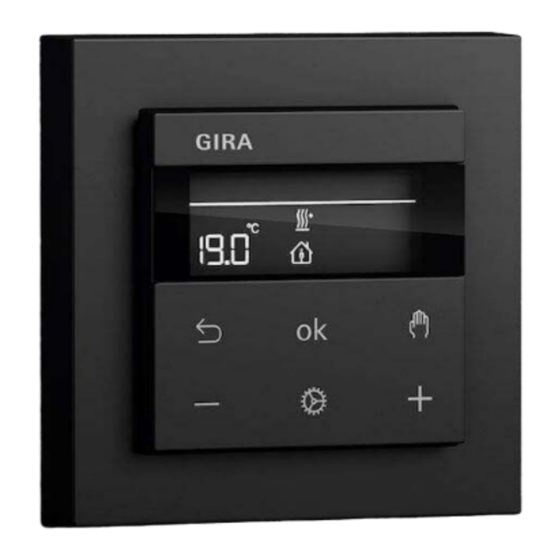
Gira System 3000 Operating Instructions Manual
Zero-voltage relay switching insert
Hide thumbs
Also See for System 3000:
- User manual ,
- Operating instructions manual (25 pages) ,
- Operating instructions (3 pages)
Subscribe to Our Youtube Channel
Summary of Contents for Gira System 3000
- Page 1 System 3000 Operating instructions Zero-voltage relay switching insert Order no. 5407 00...
- Page 2 Zero-voltage relay switching insert Table of Contents Safety instructions ...................... 3 Intended use ........................ 3 Product characteristics ...................... 3 Operation .......................... 3 Information for electrically skilled persons ................ 4 Technical data ........................ 6 Warranty.......................... 7 82406002 22.08.2022 2 / 7...
- Page 3 Zero-voltage relay switching insert Safety instructions Electrical devices may only be mounted and connected by electrically skilled persons. Serious injuries, fire or property damage possible. Please read and follow manual fully. Danger of electric shock. Always disconnect before carrying out work on the device or load.
- Page 4 Zero-voltage relay switching insert Information for electrically skilled persons DANGER! Mortal danger of electric shock. Disconnect the device. Cover up live parts. Connecting and fitting the device Image 1: Connection diagram with optional extensions Image 2: Terminal-specific cable cross-section ■ Connect the switch insert (2) according to the connection diagram (see figure 1).
- Page 5 Zero-voltage relay switching insert ■ If multiple circuit breakers supply dangerous voltages to the device or load, couple the circuit breakers or label them with a warning, to ensure disconnec- tion is guaranteed. ■ Connect the 2-wire extension (3), the 3-wire extension (4) and the push-button with NO contact (5), optionally.
- Page 6 Zero-voltage relay switching insert Image 3: Connection diagram in combination with a room temperature controller cover Switching contact for switching to cooling mode Electric underfloor heating system (max. 16 A) or electrothermal valve drives If 230 V is applied to extension input 1, cooling mode is active. Technical data Rated voltage AC 230 V ~...
- Page 7 Please submit or send faulty devices postage paid together with an error de- scription to your responsible salesperson (specialist trade/installation company/elec- trical specialist trade). They will forward the devices to the Gira Service Center. Gira Giersiepen GmbH & Co. KG...


Need help?
Do you have a question about the System 3000 and is the answer not in the manual?
Questions and answers