Advertisement
Quick Links
Product End-of-Life Disassembly Instructions
:
Storage
Product Category
Marketing Name / Model
[List multiple models if applicable.]
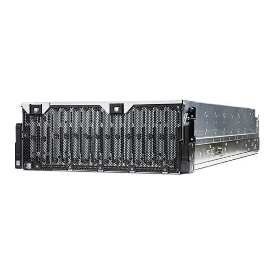
HPE Cray Cls 4U 106-18TB SAS Drive Encl
HPE Cray Cls 4U 106-10TB SAS Drive Encl
HPE Cray Cls 4U 106-12TB SAS Drive Encl
HPE Cray Cls 4U 106-14TB SAS Drive Encl
HPE Cray Cls 4U 106-16TB SAS Drive Encl
HPE Cray CS E1000 20TB 4U106 FIO HDD Encl
HPE Cray Cls 4U 106-24TB SAS Drive Encl
HPE Cray CS E1000 10TB 4U106 SED HDD Encl
HPE Cray CS E1000 16TB 4U106 SED HDD Encl
Purpose: The document is intended for use by end-of-life recyclers or treatment facilities. It provides the basic
instructions for the disassembly of HPE products to remove components and materials requiring selective treatment,
as defined by Directive 2012/19/EU of the European Parliament and of the Council on Waste Electrical and Electronic
Equipment (WEEE).
1.0 Items Requiring Selective Treatment
1.1 Items listed below are classified as requiring selective treatment.
1.2 Enter the quantity of items contained within the product which require selective treatment in the right column, as
applicable.
Item Description
Printed Circuit Boards (PCB) or Printed Circuit
Assemblies (PCA)
Batteries
Mercury-containing components
Liquid Crystal Displays (LCD) with a surface
greater than 100 sq cm
MF877-00
Template Revision C, 30-July-2018
Copyright 2018 Hewlett Packard Enterprise Development LP
HPE instructions for this template are available at
Notes
With a surface greater than 10 sq cm.
1 in each of 2 I/O modules (IOMs)
1 in each of 2 power cooling modules
1 in 24-HDD baseplane in each of 4 PCBAs
1 in 10-HDD baseplane
1 in each of 4 expander riser cards
1 in each of 8 expanders
1 in each of 2 passthrough cards
1 in EBOD PCBA
1 in midplane PCBA
All types including standard alkaline and lithium
coin or button style batteries
For example, mercury in lamps, display
backlights, scanner lamps, switches, batteries
Includes background illuminated displays with
gas discharge lamps
MF877-01
Quantity
of items
included
in
product
25 max
0
0
0
Page 1
Advertisement


Need help?
Do you have a question about the Cray Cls 4U 106-18TB and is the answer not in the manual?
Questions and answers