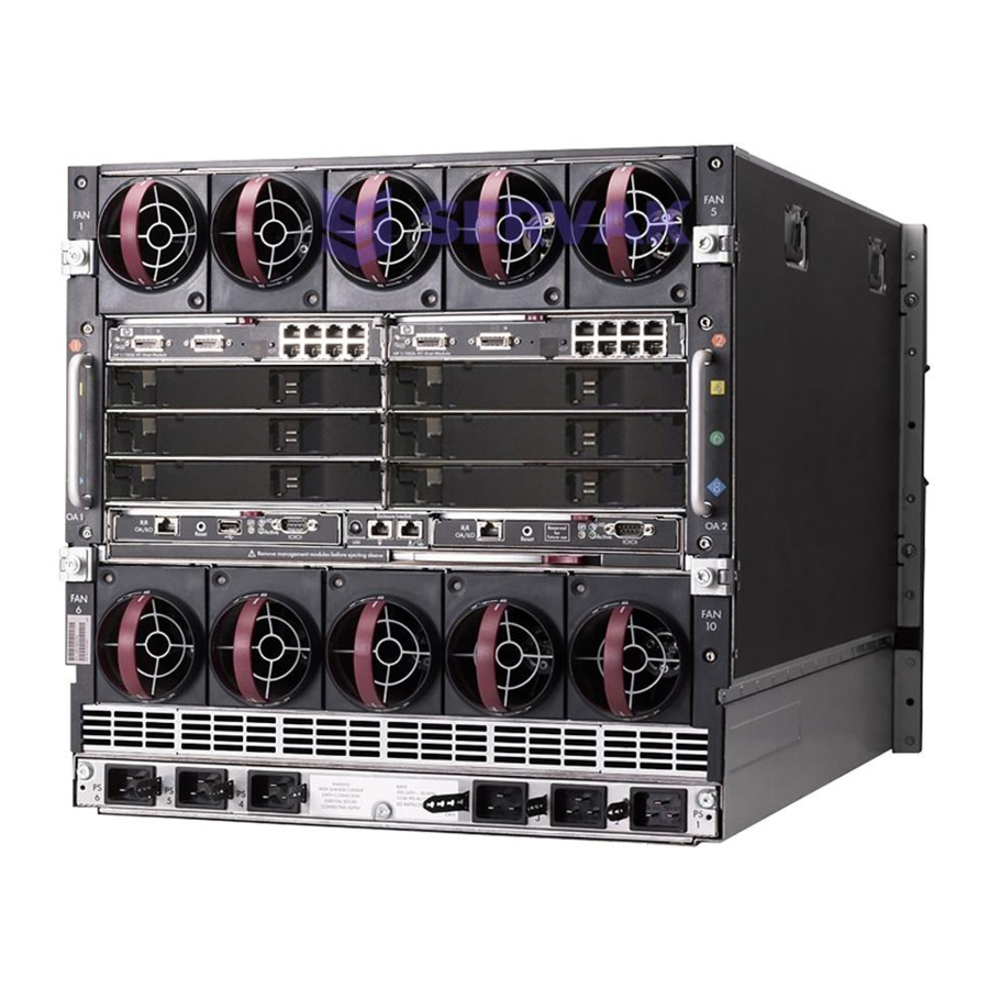
HP BladeSystem c7000 Maintenance And Service Manual
Enclosure for server blade
Hide thumbs
Also See for BladeSystem c7000:
- Setup and installation manual (103 pages) ,
- Quickspecs (43 pages) ,
- Maintenance and service manual (33 pages)
Table of Contents
Advertisement
HP BladeSystem c7000 Enclosure
Maintenance and Service Guide
Abstract
This guide is for an experienced service technician. HP assumes you are qualified in the servicing of computer equipment and trained in recognizing
hazards in products with hazardous energy levels and are familiar with weight and stability precautions for rack installations.
Part Number: 413336-014
June 2014
Edition: 14
Advertisement
Table of Contents

Related Manuals for HP BladeSystem c7000


Summary of Contents for HP BladeSystem c7000
- Page 1 Abstract This guide is for an experienced service technician. HP assumes you are qualified in the servicing of computer equipment and trained in recognizing hazards in products with hazardous energy levels and are familiar with weight and stability precautions for rack installations.
- Page 2 © Copyright 2006, 2014 Hewlett-Packard Development Company, L.P. The information contained herein is subject to change without notice. The only warranties for HP products and services are set forth in the express warranty statements accompanying such products and services. Nothing herein should be construed as constituting an additional warranty. HP shall not be liable for technical or editorial errors or omissions contained herein.
-
Page 3: Table Of Contents
Power down the server blades or workstation blades ................28 Power down the storage blade ......................29 Power down the enclosure ........................ 29 HP BladeSystem c7000 power supply or power supply blank ................. 30 Device bay blank ............................31 Device bay shelf ............................31 Half-height or full-height blade ........................ - Page 4 Troubleshooting resources ........................... 62 Onboard Administrator errors ........................62 Server blade diagnostic tools........................62 HP Insight Diagnostics ........................62 HP Insight Diagnostics survey functionality ..................63 Integrated Management Log ......................63 Array Diagnostic Utility ........................63 Component identification ......................64 Enclosure front components .........................
-
Page 5: Customer Self Repair
HP specifies in the materials shipped with a replacement CSR part whether a defective part must be returned to HP. In cases where it is required to return the defective part to HP, you must ship the defective part back to HP within a defined period of time, normally five (5) business days. The defective part must be returned with the associated documentation in the provided shipping material. - Page 6 HP sono realizzati con numerosi componenti che possono essere riparati direttamente dal cliente (CSR, Customer Self Repair). Se in fase di diagnostica HP (o un centro di servizi o di assistenza HP) identifica il guasto come riparabile mediante un ricambio CSR, HP lo spedirà direttamente al cliente per la sostituzione.
- Page 7 La mancata restituzione del componente può comportare la fatturazione del ricambio da parte di HP. Nel caso di riparazione da parte del cliente, HP sostiene tutte le spese di spedizione e resa e sceglie il corriere/vettore da utilizzare.
- Page 8 Si, durante la fase de diagnóstico, HP (o los proveedores o socios de servicio de HP) identifica que una reparación puede llevarse a cabo mediante el uso de un componente CSR, HP le enviará dicho componente directamente para que realice su sustitución. Los componentes CSR se clasifican en dos categorías:...
- Page 9 HP podrá cobrarle por el de sustitución. En el caso de todas sustituciones que lleve a cabo el cliente, HP se hará cargo de todos los gastos de envío y devolución de componentes y escogerá la empresa de transporte que se utilice para dicho servicio.
- Page 10 Opcional – Peças cujo reparo feito pelo cliente é opcional. Essas peças também são projetadas para o reparo feito pelo cliente. No entanto, se desejar que a HP as substitua, pode haver ou não a cobrança de taxa adicional, dependendo do tipo de serviço de garantia destinado ao produto.
- Page 11 No caso desse serviço, a substituição de peças CSR é obrigatória. Se desejar que a HP substitua essas peças, serão cobradas as despesas de transporte e mão-de-obra do serviço. Customer self repair 11...
- Page 12 Customer self repair 12...
- Page 13 Customer self repair 13...
- Page 14 Customer self repair 14...
-
Page 15: Illustrated Parts Catalog
Illustrated parts catalog Mechanical components Item Description Spare part number Customer self repair (on page 5) HP BladeSystem c7000 enclosure — — Rear cage — — Hardware kit 432463-001 Mandatory a) Device bay shelf — — b) Vertical cable cover* —... - Page 16 Optional—Parts for which customer self repair is optional. These parts are also designed for customer self repair. If, however, you require that HP replace them for you, there may or may not be additional charges, depending on the type of warranty service designated for your product.
- Page 17 Optional: Opcional—Peças cujo reparo feito pelo cliente é opcional. Essas peças também são projetadas para o reparo feito pelo cliente. No entanto, se desejar que a HP as substitua, pode haver ou não a cobrança de taxa adicional, dependendo do tipo de serviço de garantia destinado ao produto.
-
Page 18: System Components
Front system components Item Description Spare part number Customer self repair (on page 5) Power supply — — a) HP BladeSystem c7000 power supply 411099-001 Mandatory b) HP 2400W High Efficiency power 500242-001 Mandatory supply* c) HP BL7000 2400W Platinum power 588733-001... - Page 19 Optional—Parts for which customer self repair is optional. These parts are also designed for customer self repair. If, however, you require that HP replace them for you, there may or may not be additional charges, depending on the type of warranty service designated for your product.
- Page 20 Optional: Opcional—Peças cujo reparo feito pelo cliente é opcional. Essas peças também são projetadas para o reparo feito pelo cliente. No entanto, se desejar que a HP as substitua, pode haver ou não a cobrança de taxa adicional, dependendo do tipo de serviço de garantia destinado ao produto.
-
Page 21: Rear System Components
Description Spare part number Customer self repair (on page 5) Interconnect module (switch) — — a) HP GbE2c Ethernet Blade Switch for HP 414037-001 Mandatory c-Class BladeSystem b) HP GbE2c Layer 2/3 Ethernet Blade 438475-001 Mandatory Switch for c-Class BladeSystem*... - Page 22 Mandatory Module for c-Class BladeSystem* j) HP 4Gb Virtual Connect Fibre Channel 410152-001 Mandatory Module for c-Class BladeSystem* k) HP 4X DDR IB Switch Module for HP 410408-001 Mandatory c-Class BladeSystem* l) HP BLc 1/10GB-F Virtual Connect Enet 447103-001 Mandatory...
- Page 23 Optional—Parts for which customer self repair is optional. These parts are also designed for customer self repair. If, however, you require that HP replace them for you, there may or may not be additional charges, depending on the type of warranty service designated for your product.
- Page 24 Optional: Opcional—Peças cujo reparo feito pelo cliente é opcional. Essas peças também são projetadas para o reparo feito pelo cliente. No entanto, se desejar que a HP as substitua, pode haver ou não a cobrança de taxa adicional, dependendo do tipo de serviço de garantia destinado ao produto.
- Page 25 Illustrated parts catalog 25...
-
Page 26: Removal And Replacement Procedures
Removal and replacement procedures Required tools The following items are required for some procedures: • T-10 Torx screwdriver • T-15 Torx screwdriver Safety considerations Before performing service procedures, review all the safety information. Preventing electrostatic discharge To prevent damaging the system, be aware of the precautions you need to follow when setting up the system or handling parts. - Page 27 WARNING: To reduce the risk of personal injury or equipment damage when unloading a rack: • At least two people are needed to safely unload the rack from the pallet. An empty 42U rack can weigh as much as 115 kg (253 lb), can stand more than 2.1 m (7 ft) tall, and might become unstable when being moved on its casters.
-
Page 28: Preparing The Enclosure
WARNING: To reduce the risk of personal injury from hot surfaces, allow the drives and the internal system components to cool before touching them. WARNING: To reduce the risk of electric shock or damage to the equipment, enter enclosures or perform service on system components only as instructed in the user documentation. -
Page 29: Power Down The Storage Blade
This method forces the server blades or workstation blades to enter standby mode without properly exiting applications and the OS. It provides an emergency shutdown method if an application stops responding. • Execute one of the following commands using the Onboard Administrator CLI: poweroff server [bay number] poweroff server [bay number] force The first command initiates a controlled shutdown of applications and the OS before the server blades... -
Page 30: Hp Bladesystem C7000 Power Supply Or Power Supply Blank
-48vDC power supplies in one enclosure. Install only one type of power supply in a single enclosure. NOTE: To access all power supply bays, slide the HP BladeSystem Insight Display to the right or left. To remove the component: Press the release button. -
Page 31: Device Bay Blank
Device bay blank Remove the blank from the enclosure: CAUTION: For best cooling practices, do not operate the enclosure for extended periods with more than one component or blank removed. When removing an active component, replace it with a blank. To replace the component, reverse the removal procedure. - Page 32 Item Description Blade Zone 1 Blade Zone 2 Blade Zone 3 Blade Zone 4 Storage blades and tape blades can be installed in the same quadrant as both full-height and half-height blades. A bracket ships with each SB40c Storage Blade that allows a half-height blade to be mounted on top of the storage blade.
- Page 33 Slide the device bay shelf locking tab to the left to open it. Push the device bay shelf back until it stops, lift the right side slightly to disengage the two tabs from the divider wall, and then rotate the right edge downward (clockwise). Removal and replacement procedures 33...
-
Page 34: Half-Height Or Full-Height Blade
CAUTION: This procedure provides instructions for replacement of a failed part only. To change the configuration of components, see the appropriate HP BladeSystem c-Class enclosure setup and installation guide. The c7000 enclosure is divided into four quadrants by the vertical support metal work. Within each quadrant, a removable divider supports half-height blades. - Page 35 Item Description Blade Zone 1 Blade Zone 2 Blade Zone 3 Blade Zone 4 Storage blades and tape blades can be installed in the same quadrant as both full-height and half-height blades. A bracket ships with each SB40c Storage Blade that allows a half-height blade to be mounted on top of the storage blade.
-
Page 36: Hp Bladesystem Insight Display
When removing an active component, replace it with a blank. To replace the component, reverse the removal procedure. HP BladeSystem Insight Display To remove the component: Power down the enclosure (on page 29). - Page 37 ("Device bay blank" on page 31) Power supplies or blanks: bays 1-4 ("HP BladeSystem c7000 power supply or power supply blank" on page 30) Remove the three T-15 Torx screws that secure the Insight Display cable center cover, and then remove the cover.
-
Page 38: Fan Blank
Carefully remove the Insight Display cable through the cable channel. To replace the component, reverse the removal procedure. Fan blank To remove the component: Turn the handle counterclockwise. Remove the blank. CAUTION: For best cooling practices, do not operate the enclosure for extended periods with more than one component or blank removed. -
Page 39: Active Cool 200 Fan
Active Cool 200 fan CAUTION: This procedure provides instructions for replacement of a failed part only. To change the configuration of components, see the appropriate HP BladeSystem c-Class enclosure setup and installation guide. To remove the component: Turn the handle counterclockwise. -
Page 40: Enclosure Front Bezels (Platinum Models Only)
Remove the blank. CAUTION: For best cooling practices, do not operate the enclosure for extended periods with more than one component or blank removed. When removing an active component, replace it with a blank. To replace the component, slide the component into the bay until it locks into place. Enclosure front bezels (Platinum models only) Remove the component as indicated. -
Page 41: Interconnect Bay Dividers
CAUTION: This procedure provides instructions for replacement of a failed part only. To change the configuration of components, see the appropriate HP BladeSystem c-Class enclosure setup and installation guide. To remove the component: CAUTION: To prevent data loss, redirect network activity or be sure that all critical network activity has stopped before removing the interconnect module. -
Page 42: Onboard Administrator Blank
Remove the interconnect bay divider. To replace the component, reverse the removal procedure. Onboard Administrator blank Remove the component as indicated. CAUTION: For best cooling practices, do not operate the enclosure for extended periods with more than one component or blank removed. When removing an active component, replace it with a blank. -
Page 43: Onboard Administrator
Onboard Administrator To remove the component: Disconnect all cables from the component. Press the release tab and open the handle. Remove the Onboard Administrator module. CAUTION: For best cooling practices, do not operate the enclosure for extended periods with more than one component or blank removed. When removing an active component, replace it with a blank. -
Page 44: Ac Input Module
Remove the Onboard Administrator tray. CAUTION: For best cooling practices, do not operate the enclosure for extended periods with more than one component or blank removed. When removing an active component, replace it with a blank. To replace the component, reverse the removal procedure. AC input module To remove the component: Power down the server blades... -
Page 45: Ac Control Module
Configure the AC input module. For more information, see "Midplane assembly (on page 53)." To replace the component, reverse the removal procedure. AC control module To remove the component: Disconnect all USB connections from the Onboard Administrator to the control module. Loosen the two slotted screws that secure the control module. - Page 46 Power supplies ("HP BladeSystem c7000 power supply or power supply blank" on page 30) Remove the fans ("Active Cool 200 fan" on page 39). Remove the interconnect switches and Pass-Thru modules ("Interconnect switch or Pass-Thru module" on page 40). Remove the Onboard Administrator modules ("Onboard...
-
Page 47: Insight Display Front-To-Rear Interconnect Board
34). Remove the device bay blanks ("Device bay blank" on page 31). Remove the power supplies ("HP BladeSystem c7000 power supply or power supply blank" on page 30). Remove the fans ("Active Cool 200 fan" on page 39). - Page 48 Remove the rear cage ("Rear cage" on page 45). WARNING: To reduce the risk of personal injury or equipment damage, at least two people are needed to safely move the rear cage. Remove the three T-15 Torx screws that secure the Insight Display cable center cover, and then remove the cover.
-
Page 49: Insight Display Signal Pass-Thru Board
Remove the two slotted T-15 Torx screws that secure the interconnect board. Remove the interconnect board. To replace the component, reverse the removal procedure. Insight Display signal pass-thru board WARNING: To reduce the risk of damage to the midplane and component connectors, always remove or disengage and extend all blades and power supplies approximately 8 cm (3 in) before removing or installing the rear cage. - Page 50 Disengage and extend the following components approximately 8 cm (3 in): Half-height and full-height blades ("Half-height or full-height blade" on page 34) Power supplies ("HP BladeSystem c7000 power supply or power supply blank" on page 30) Remove the fans ("Active Cool 200 fan" on page 39).
-
Page 51: Location Discovery Services Board (Platinum Models Only)
Disconnect the pass-thru board from the cable. To replace the component, reverse the removal procedure. Location discovery services board (Platinum models only) To remove the component: Power down the server blades ("Power down the server blades or workstation blades" on page 28). Power down the enclosure (on page 29). - Page 52 Remove the location discovery services board cover. Disconnect the cable from the location discovery services board. Removal and replacement procedures 52...
-
Page 53: Midplane Assembly
Locate the enclosure tag on the front, side, or rear of the enclosure. • Access the Onboard Administrator. • Log in to the Onboard Administrator CLI and run the command Show Enclosure Info. See the HP BladeSystem Onboard Administrator Command Line Interface User Guide for information on accessing the CLI. WARNING:... - Page 54 ("Half-height or full-height blade" on page 34) Power supplies ("HP BladeSystem c7000 power supply or power supply blank" on page 30) — The power supply in bay 3 or 4 must be completely removed, and then the Insight Display must be moved in front of that power supply bay to enable the other power supplies to be removed or extended.
- Page 55 Remove the eight slotted T-15 Torx screws that secure the midplane assembly, and then remove the midplane assembly from the rear cage. To replace the midplane assembly, reverse the removal procedure. CAUTION: The LCD cable must be correctly routed for proper operation. To route the LCD cable: When installing the midplane assembly onto the rear cage assembly, ensure the LCD cable is routed behind the interconnect module rubber boot and through the sheet-metal gaps.
- Page 56 CAUTION: Failure to complete the following procedure might cause inaccurate or incomplete information to appear in HP SIM and Onboard Administrator. Using the Insight Display, navigate to the Enclosure Info screen. Verify that the enclosure serial number matches the enclosure serial number on the label on the enclosure mounting bracket.
- Page 57 4—DC power 5—Single Phase Intelligent PDU Install all VC Ethernet modules, VC-FC modules, and all other interconnect modules in the same bay they were removed from. Reconnect all cables to those modules to the same ports they were removed from. Wait two minutes.
-
Page 58: Cabling
Cabling Single-phase AC configuration Three-phase AC configuration Cabling 58... -
Page 59: Hp Bladesystem C7000 Enclosure Dc Configuration
HP BladeSystem c7000 Enclosure DC configuration Item Description Chassis grounding lugs DC connectors for power supply bay 1 DC connectors for power supply bay 2 DC connectors for power supply bay 3 DC connectors for power supply bay 4 DC connectors for power supply bay 5... -
Page 60: Onboard Administrator Cabling
Onboard Administrator cabling Item Connector Description OA/iLO Ethernet 1000BaseT RJ45 connector, which provides Ethernet access to the Onboard Administrator and the iLO on each server blades or workstation blades. Also supports interconnect modules with management processors configured to use the enclosure management network. -
Page 61: Onboard Administrator With Kvm Cabling
Onboard Administrator with KVM cabling Item Connector Description OA/iLO Ethernet 1000BaseT RJ45 connector, which provides Ethernet access to the Onboard Administrator and the iLO on each server blades or workstation blades. Also supports interconnect modules with management processors configured to use the enclosure management network. -
Page 62: Diagnostic Tools
OA GUI>Enclosure settings>Enclosure configuration scripts • OA CLI>Execute the following CLI command: SHOW ALL Review this inventory report where appropriate and have this report on hand available when contacting HP Support. For more information, see the HP website (http://www.hp.com/go/OAlog). Server blade diagnostic tools... -
Page 63: Hp Insight Diagnostics Survey Functionality
For more information, see the Management CD in the HP ProLiant Essentials Foundation Pack. Array Diagnostic Utility The HP Array Diagnostics Utility is a web-based application that creates a report of all HP storage controllers and disk drives. This report provides vital information to assist in identifying faults or conditions that may require attention. -
Page 64: Component Identification
Component identification Enclosure front components Item Description Device bays* Air intake slot (Do not block.) Power supply bay 1 Power supply bay 2 Power supply bay 3 Power supply bay 4 Insight Display Power supply bay 5 Power supply bay 6 Air intake slot (Do not block.) *For more information, see "Device bay numbering (on page 64)."... - Page 65 IMPORTANT: When looking at the rear of the enclosure, front device bay numbering is reversed. Full-height device bay numbering Half-height device bay numbering Component identification 65...
-
Page 66: Power Supply Leds
Power supply LEDs Power LED 1 Fault LED 2 Condition (green) (amber) No AC power to the power supply Normal Power supply failure Power supply bay numbering Component identification 66... -
Page 67: Hp Bladesystem Insight Display
Insight Display overview The Insight Display enables the rack technician to configure the enclosure initially. It also provides information about the health and operation of the enclosure. See the HP BladeSystem Onboard Administrator User Guide for additional information. The Insight Display background color varies with the condition of the enclosure health: •... -
Page 68: Enclosure Rear Components
HP BladeSystem Insight Display components Item Description Function Insight Display screen Displays Main Menu error messages and instructions Left arrow button Moves the menu or navigation bar selection left one position Right arrow button Moves the menu or navigation bar selection right one position... -
Page 69: Interconnect Module Bay Numbering
Item Description Fan bay 1 Fan bay 2 Fan bay 3 Fan bay 4 Fan bay 5 Interconnect bay 2 Interconnect bay 4 Interconnect bay 6 Interconnect bay 8 Onboard Administrator bay 2 Power supply exhaust vent (do not block) Fan bay 10 Fan bay 9 Fan bay 8... -
Page 70: Onboard Administrator Components
Server blade signal Interconnect bay Interconnect bay label number 1, 2 NICs 1, 2, 3, and 4 (embedded) 3, 4 Mezzanine 1 5, 6 and then 7, 8 Mezzanine 2 7, 8 and then 5, 6 Mezzanine 3 NOTE: For information on the location of LEDs and ports on individual interconnect modules, see the documentation that ships with the interconnect module. -
Page 71: Onboard Administrator Leds And Buttons
Onboard Administrator LEDs and buttons Item Description Onboard Administrator UID LED Enclosure UID LED and UID button Onboard Administrator active LED Onboard Administrator health LED Onboard Administrator reset button Onboard Administrator with KVM LEDs and buttons Item Description Onboard Administrator UID LED Component identification 71... -
Page 72: Fan Bay Numbering
Item Description Enclosure UID LED and UID button Onboard Administrator health LED Onboard Administrator active LED Onboard Administrator reset button Fan bay numbering Fan LED LED color Fan status The fan is working. Solid green The fan has failed. Solid amber Component identification 72... - Page 73 LED color Fan status See the Insight Display screen. Flashing amber Component identification 73...
-
Page 74: Specifications
Specifications Environmental specifications Specification Value Temperature range* 10°C to 35°C (50°F to 95°F) Operating -30°C to 60°C (-22°F to 140°F) Non-operating Wet bulb temperature 28ºC (82.4ºF) Operating 38.7ºC (101.7ºF) Non-operating Relative humidity (noncondensing)** 20% to 80% Operating 5% to 95% Non-operating * All temperature ratings shown are for sea level. -
Page 75: Power Specifications
(maximum) 2700 W Rated input power per power supply (maximum) Single-phase power Specification HP BladeSystem HP 2400W High HP BL7000 2400W c7000 Power Supply Efficiency Power Supply Platinum Power Supply IEC-320 C19-C20 1.22 IEC-320 C19-C20 1.22 m IEC-320 C19-C20 1.22 m (4... -
Page 76: Three-Phase Power (North America/Japan)
Three-phase power (North America/Japan) Specification HP BladeSystem HP 2400W High HP BL7000 2400W c7000 Power Supply Efficiency Power Supply Platinum Power Supply NEMA L15-30p 2.44 m NEMA L15-30p 2.44 m NEMA L15-30p 2.44 m (10 Power cords (2) (10 ft) -
Page 77: Acronyms And Abbreviations
Acronyms and abbreviations Array Diagnostics Utility Customer Self Repair electrostatic discharge HVDC High Voltage DC Integrated Lights-Out Integrated Management Log Onboard Administrator small form-factor pluggable Systems Insight Manager Acronyms and abbreviations 77... -
Page 78: Documentation Feedback
Documentation feedback HP is committed to providing documentation that meets your needs. To help us improve the documentation, send any errors, suggestions, or comments to Documentation Feedback (mailto:docsfeedback@hp.com). Include the document title and part number, version number, or the URL when submitting your feedback. -
Page 79: Index
HP BladeSystem Insight Display 36, 67 cabling, Onboard Administrator module 60 HP BladeSystem Insight Display components 68 cabling, service port 60 HP BladeSystem Insight Display screen 64, 67, 68 cautions 26 HP BladeSystem Insight Display, navigating 68 components 15, 21, 64... - Page 80 Onboard Administrator 43, 62 Onboard Administrator blank 42 Onboard Administrator components 70 Onboard Administrator module, cabling 60, 61 Onboard Administrator tray 43 overview, HP BladeSystem Insight Display 67 part numbers 15, 18 pass-thru module 40 power specifications 75 power supply 30...
Need help?
Do you have a question about the BladeSystem c7000 and is the answer not in the manual?
Questions and answers