HP BladeSystem c7000 Setup And Installation Manual
Enclosure
Hide thumbs
Also See for BladeSystem c7000:
- Maintenance and service manual (80 pages) ,
- Setup and installation manual (70 pages) ,
- Quickspecs (43 pages)
Table of Contents
Advertisement
HP BladeSystem c7000 Enclosure
Setup and Installation Guide
Abstract
This guide describes identification, operations, setup, configuration and utilities, troubleshooting, regulatory notices, specifications, and technical
support. This guide is for an experienced service technician. HP assumes you are qualified in the servicing of computer equipment, trained in
recognizing hazards in products, and are familiar with weight and stability precautions.
Part Number: 411272-401
February 2013
Edition: 10
Advertisement
Table of Contents

Related Manuals for HP BladeSystem c7000


Summary of Contents for HP BladeSystem c7000
-
Page 1: Hp Bladesystem C7000 Enclosure
This guide describes identification, operations, setup, configuration and utilities, troubleshooting, regulatory notices, specifications, and technical support. This guide is for an experienced service technician. HP assumes you are qualified in the servicing of computer equipment, trained in recognizing hazards in products, and are familiar with weight and stability precautions. - Page 2 © Copyright 2006, 2013 Hewlett-Packard Development Company, L.P. The information contained herein is subject to change without notice. The only warranties for HP products and services are set forth in the express warranty statements accompanying such products and services. Nothing herein should be construed as constituting an additional warranty. HP shall...
-
Page 3: Table Of Contents
Enclosure rear components ........................16 Fan bay numbering ........................17 Fan LED ............................18 Onboard Administrator components ....................18 HP c7000 Onboard Administrator with KVM components ..............19 Interconnect bay numbering ......................20 Installation ..........................21 Installation overview ..........................21 Disassembling the enclosure ........................ - Page 4 Powering up the enclosure ........................59 Single-phase AC configuration ......................59 Three-phase AC configuration ......................64 HP BladeSystem Insight Display ....................65 Insight Display overview ........................... 65 Running the Insight Display installation steps ....................65 Navigating the Insight Display ........................69 Health Summary screen ........................
- Page 5 Preventing electrostatic discharge ......................97 Grounding methods to prevent electrostatic discharge .................. 97 Acronyms and abbreviations ......................98 Documentation feedback ......................100 Index ............................101 Contents 5...
-
Page 6: Planning The Installation
I/O connector on the front of a blade Fan blank A mandatory insert installed in any unused fan bay HP Active Cool 200 Fan (quantity as A fan used to cool the components installed in the ordered) -
Page 7: Rack Requirements
* Not shown Rack requirements The enclosure is compatible with the following racks: • All HP 10000 and 10000G2 Series racks except the HP 10614 rack. NOTE: The system is optimized for 10000 Series racks. • Telco racks •... -
Page 8: Rack-Free Environment Requirements
— Maximum rail length: 86.4 cm (34 in) Rack-free environment requirements The HP BladeSystem c7000 Enclosure (referred to as the enclosure) can be used in a rack-free environment. The following conditions must be met when performing a rack-free installation: •... - Page 9 WARNING: The enclosure is very heavy. To reduce the risk of personal injury or damage to the equipment: Observe local occupational health and safety requirements and guidelines for manual • material handling. • Remove all installed enclosure components from their enclosures before installing or moving the enclosures.
-
Page 10: Space And Airflow Requirements
Leave a minimum clearance of 121.9 cm (48 in) from the back of the rack to the rear of another rack or row of racks. HP BladeSystem servers draw cool air in through the front and expel warm air through the rear of the enclosure. Therefore, the front of the rack enclosure must be adequately ventilated to enable ambient room air to enter the enclosure, and the rear of the enclosure must be adequately ventilated to enable the warm air to escape from the enclosure. -
Page 11: Temperature Requirements
Because of the high ground-leakage currents associated with this equipment, HP recommends the use of a PDU that is either permanently wired to the building’s branch circuit or includes a nondetachable cord that is wired to an industrial-style plug. -
Page 12: Component And Led Identification
Component and LED identification Enclosure front components Item Description Device bays* Air intake slot (Do not block.) Power supply bay 1 Power supply bay 2 Power supply bay 3 Power supply bay 4 Insight Display Power supply bay 5 Power supply bay 6 Air intake slot (Do not block.) *For more information, see "Device bay numbering (on page 14)."... -
Page 13: Power Supply Bay Numbering
Power supply bay numbering Power supply LEDs Power LED 1 Fault LED 2 Condition (green) (amber) No AC power to the power supply Normal Power supply failure For power supply configuration information, see Installing a power supply (on page 29). Component and LED identification 13... -
Page 14: Device Bay Numbering
Device bay numbering Each enclosure requires interconnects to provide network access for data transfer. Interconnects reside in bays located on the rear of the enclosure. Be sure to review device bay numbering to determine which external network connections on the interconnects are active. IMPORTANT: When looking at the rear of the enclosure, front device bay numbering is reversed. -
Page 15: Hp Bladesystem Insight Display Components
HP provides built-in location awareness in the new ProLiant servers, a capability that works hand-in-hand with technology in the new HP Intelligent Series racks. Together these technologies provide the rack identification number and precise U location of the servers. This information is communicated through SIM, ICPM, and HP iPDUs. -
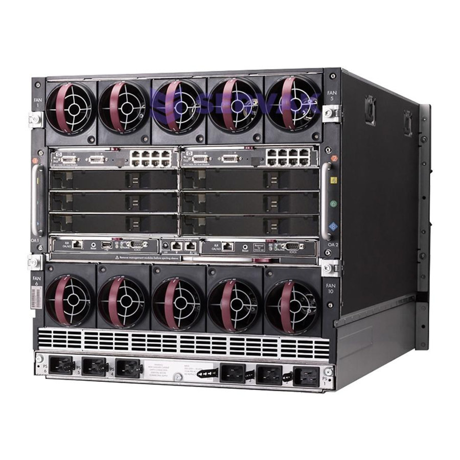
Page 16: Enclosure Rear Components
The following figure shows the location of the contacts on the c7000 enclosure that enable use of LDS. Enclosure rear components Item Description Fan bay 1 Fan bay 2 Fan bay 3 Fan bay 4 Fan bay 5 Interconnect bay 2 Interconnect bay 4 Interconnect bay 6 Interconnect bay 8... -
Page 17: Fan Bay Numbering
Item Description Onboard Administrator bay 2 Power supply exhaust vent (do not block) Fan bay 10 Fan bay 9 Fan bay 8 Fan bay 7 Fan bay 6 AC power connectors Onboard Administrator bay 1 Interconnect bay 7 Interconnect bay 5 Interconnect bay 3 Interconnect bay 1 Fan bay numbering... -
Page 18: Fan Led
Fan LED LED color Fan status The fan is working. Solid green The fan has failed. Solid amber See the Insight Display screen. Flashing amber Onboard Administrator components Item Description Onboard Administrator bay 1 Onboard Administrator bay 2 (redundant, if used) Enclosure link-up port Enclosure link-down port Component and LED identification 18... -
Page 19: Hp C7000 Onboard Administrator With Kvm Components
HP c7000 Onboard Administrator with KVM components Item Name Description Reset button — OA/iLO management port Ethernet 100BaseT RJ45 connector, which provides Ethernet access to the Onboard Administrator and the iLO on each blade. Also supports interconnect modules with management processors... -
Page 20: Interconnect Bay Numbering
Item Name Description Serial connector Serial RS232 DB-9 connector with PC standard pinout. Connect a computer with a null-modem serial cable to the Onboard Administrator command line interface (CLI). VGA DB-15 connector with PC standard pinout. To access the KVM menu or Onboard Administrator CLI, connect a VGA monitor... -
Page 21: Installation
Installation Installation overview To set up and install the enclosure: Disassemble the enclosure ("Disassembling the enclosure" on page 21). For rack-free installations ("Rack-free installation" on page 24), set up the enclosure on an appropriate surface, then install the rear cage and enclosure components. For rack installations, install the enclosure into the rack ("Installing the enclosure into the rack"... - Page 22 With the enclosure still on the pallet, remove all components from the front and rear of the enclosure. Remove the rear cage: Loosen the thumbscrews and open the hinges completely. Installation 22...
- Page 23 Use the handles to extend the rear cage until the release levers engage on both sides of the rear cage. Grasp the handholds below the release levers. Disengage the release levers on both sides of the rear cage. CAUTION: When removing and lifting the rear cage, always grasp the handholds as far forward as possible.
-
Page 24: Rack-Free Installation
Use the handholds to extend and remove the rear cage from the enclosure. Rack-free installation WARNING: To reduce the risk of personal injury or damage to the equipment in a rack-free environment: Never stack the enclosure on top of another enclosure. •... -
Page 25: Measuring With The Rack Template
Use the rack template ("Measuring with the rack template" on page 25) to mark the locations for the rack rails. Install the rack rails ("Installing the rack rails" on page 25) for each enclosure. Install the enclosure into the rack ("Installing the enclosure into the rack"... -
Page 26: Installing The Enclosure Into The Rack
Slide the front end of the rail to the rack front column. When fully seated, the rack rail will lock into place. Repeat the procedure for the right rack rail. Installing the enclosure into the rack The empty enclosure with the rear cage installed weighs 58.6 kg (129 lb). When the enclosure is disassembled, the empty enclosure without the rear cage installed weighs 35.5 kg (78 lb). - Page 27 Push the handles down on each side of the enclosure, and slide the enclosure fully into the rack. Tighten the thumbscrews to secure the enclosure to the rack. Install the rear cage into the enclosure. ("Installing the rear cage into the enclosure"...
-
Page 28: Installing The Rear Cage Into The Enclosure
Installing the rear cage into the enclosure Open all hinges completely. Position the rear cage at the rear of the enclosure, and align the rear cage guiding fins with the guiding groove in the rack rails. Slide the rear cage fully into the enclosure. CAUTION: Do not touch or bump rear cage connector pins when installing the rear cage into the enclosure. -
Page 29: Component Installation
See "Running the Insight Display installation steps (on page 65)" for information on the types of power configurations available and how to set them up. If your HP BladeSystem c7000 Enclosure is equipped with a three-phase power configuration, six power supplies are required. Single-phase configurations can have fewer than six power supplies. - Page 30 To install a power supply: Slide the HP BladeSystem Insight Display to the right or left to gain access to all power supply bays. Open the power supply bracket. Insert the power supply into the enclosure, and then close the bracket.
-
Page 31: Installing Blades
The lower tape or storage blade cannot be removed without first removing the upper half-height blade. Installing a full-height blade The HP BladeSystem c7000 Enclosure ships with four device bay shelves to support half-height devices. To install a full-height device, remove the device bay shelf and the corresponding blanks. - Page 32 Remove the blank. Remove the three adjacent blanks. Remove the device bay shelf ("Removing a device bay shelf" on page 34). Remove the connector covers. Installation 32...
- Page 33 Prepare the blade for installation. Install the blade. CAUTION: To prevent improper cooling and thermal damage, do not operate the blade or the enclosure unless all drive and device bays are populated with either a component or a blank. Install blanks in any empty bays. Installation 33...
- Page 34 Removing a device bay shelf Remove the blank. Slide the device bay shelf locking tab to the left to open it. Installation 34...
-
Page 35: Creating A Full-Height Device Bay Blank
Push the device bay shelf back until it stops, lift the right side slightly to disengage the two tabs from the divider wall, and then rotate the right edge downward (clockwise). Lift the left side of the device bay shelf to disengage the three tabs from the divider wall, and then remove it from the enclosure. - Page 36 Fit the coupler plate into the slots on top of the blank, and then slide the coupler plate back until it snaps into place. Fit the slots on the bottom of the second blank on to the tabs on the coupler plate, and then slide the second blank forward until it snaps in place.
-
Page 37: Installing A Half-Height Blade
Installing a half-height blade Remove the blank. Install the device bay shelf, if applicable. Install the blade in the empty bay. Installing a device bay shelf You must install the device bay shelf to support half-height devices. To install the device bay shelf: Installation 37... - Page 38 Remove the full-height blade, storage blade, or device bay blank. To unlock device bay shelf locking tab, slide it to the left. Installation 38...
- Page 39 Tilt the shelf at an angle with the left edge up. Align the three tabs on the left edge of the shelf with the openings in the enclosure, and then push the device bay shelf up. CAUTION: Be sure that all five tabs (three on the left side of the shelf and two on the right side of the shelf) are fully engaged before sliding the shelf forward to complete the installation.
-
Page 40: Connecting Locally To A Server Blade With Video And Usb Devices
To lock device bay shelf locking tab, slide it to the right. Connecting locally to a server blade with video and USB devices Use the local I/O cable to connect a monitor and any of the following USB devices: • USB hub •... -
Page 41: Accessing Local Media Devices
Use the following configuration when configuring a blade or loading software updates and patches from a USB CD/DVD-ROM or a USB diskette drive. Connect the HP c-Class Blade SUV cable to the blade. Connect the video connector to a monitor. -
Page 42: Installing Fans
USB CD/DVD-ROM drive or diskette drive Installing fans The HP BladeSystem c7000 Enclosure ships with four HP Active Cool 200 Fans and supports up to 10 fans. Install fans in even-numbered groups, based on the total number of blades installed in the enclosure. - Page 43 Turn the handle counterclockwise to the unlock position, and pull the fan or fan blank from the enclosure. Slide the fan into the enclosure until it locks in place. NOTE: When installing a fan in the top row of fan bays, orient the fan so that the LED is in the lower right corner.
-
Page 44: Installing Onboard Administrator Modules
Installing Onboard Administrator modules The HP BladeSystem c7000 Enclosure is shipped with one HP BladeSystem Onboard Administrator with KVM module installed and can support up to two Onboard Administrator modules. Install Onboard Administrator modules based on the total number ordered: •... - Page 45 For local access to the enclosure: Connect a monitor (1) to the VGA connector (6) on the HP Onboard Administrator with KVM. Connect a USB hub (4) to the USB connector (5) on the HP Onboard Administrator with KVM. Installation 45...
-
Page 46: Installing Interconnect Modules
Connect a USB mouse (2) and keyboard (3) to the USB hub (4). To connect the HP Onboard Administrator with KVM to an HP Server Console Switch or an HP IP Console Switch: Connect the KVM interface adapter (2) to the VGA connector (4) and the USB connector (3) on the HP Onboard Administrator with KVM. - Page 47 IMPORTANT: If the mezzanine card is not installed properly or the interconnect module installation does not coincide with the mezzanine card installation, the ports on the interconnect module will not function. NOTE: For more information on how and where to install mezzanine cards, see the server-specific user guide.
-
Page 48: Mapping To Interconnect Ports
Mapping to interconnect ports Several port types are referenced in the following tables. • Examples of 1x ports are 1-Gb Ethernet (1 GbE) switch modules and Fibre Channel interconnect modules. • An example of a 2x port is a Serial Attached SCSI (SAS) interconnect module. (Reserved for future use.) •... - Page 49 Mapping half-height blades The following table lists the available configurations for half-height devices installed in device bay N (1–16). Connection Port number Connects to interconnect Comments bay/port NIC 1 1/Port N One or two single-wide Embedded NIC NIC 2 2/Port N Ethernet interconnect modules 1x/2x port 1 3/Port N...
- Page 50 Connection Port number Connects to interconnect Comments bay/port 1x/2x port 1 5 / port N One or two single-wide Mezzanine slot 2—1x or 1x/2x port 2 6 / port N interconnect modules 2x cards 1x/2x port 3 7 / port N 1x/2x port 4 8 / port N 4x port 1...
-
Page 51: Mapping Bl2X220C Blades
Connection Port number Connects to interconnect Comments bay/port NIC 1 1/Port N+8 One or two single-wide NIC 2 2/Port N+8 Ethernet interconnect modules NIC 3 1/Port N NIC 4 2/Port N 1x/2x port 1 3/Port N One or two single-wide Mezzanine slot 1—1x or 1x/2x port 2 4/Port N... - Page 52 Interconnect device mapping for double dense server blades The following table lists the available configurations for double dense server blades installed in device bay N (1-16). Connection Port number Connects to interconnect bay/port NIC 1 (ENET:1) 1/Port N Server A Embedded NIC 2 (ENET:2) 3/Port N Port 1...
- Page 53 • B side To support network connections for specific signals, install an interconnect module in the bay corresponding to the embedded NIC or mezzanine signals. Interconnect bay identification Bay-to-bay crosslinks Four trace SerDes signals between adjacent bays are provided in the enclosure midplane to permit bay-to-bay communications.
-
Page 54: Device Bay Crosslinks
Device bay crosslinks Device bay crosslinks are wired between adjacent horizontal device bay pairs. For half-height blades, these signals connect a four-lane PCIe module to a partner blade such as a tape blade or a PCI expansion blade. For full-height blades, these signals are used to connect a PCIe module to a partner blade in the lower adjacent bay and require a PCIe pass-thru mezzanine card installed in mezzanine connector 3. -
Page 55: Removing Interconnect Bay Dividers
Removing interconnect bay dividers The enclosure ships with interconnect bay dividers installed. The interconnect bay dividers must be removed before installing double-wide interconnect modules. To remove an interconnect bay divider, press the release tab, and pull the interconnect bay divider out of the enclosure. Installing interconnect bay dividers The enclosure ships with interconnect bay dividers installed. -
Page 56: Cabling And Powering Up The Enclosure
Cabling and powering up the enclosure Cabling the enclosure After all system hardware is installed, cable the components. See the HP ProLiant BladeSystem c-Class Site Planning Guide on the Documentation CD or the HP website (http://www.hp.com) for additional cabling and site planning requirements. -
Page 57: Enclosure Link Cabling
To utilize intelligent power discovery, connect the cables to an intelligent single-phase AC module, and then to the OAs. This feature is only available on HP BladeSystem c7000 Platinum Enclosures. For more information on intelligent power discovery, see the HP Intelligent Power Distribution Unit User Guide on the HP website (http://www.hp.com/support/manuals). -
Page 58: Cabling A Pc To The Enclosure Service Port
NOTE: The HP BladeSystem c-Class enclosure link ports are not compatible with the HP BladeSystem p-Class enclosure link ports. To link the enclosures, use a standard Category 5 (CAT5) patch cable to connect the enclosure link-down port on the first enclosure to the enclosure link-up port on the second enclosure. -
Page 59: Cabling The Network To The Enclosure
Open a web browser on the PC and enter the active Onboard Administrator module Service IP address found in the Enclosure Info screen in step 2. Log into the Onboard Administrator. For more information on using Onboard Administrator, see the HP BladeSystem Onboard Administrator User Guide. - Page 60 • Single-phase AC configuration using the HP Single-Phase Intelligent Power Module To cable the enclosure using a single-phase AC configuration: Connect the AC power cables to the power connectors on the rear of the enclosure corresponding to the power supply that was populated on the front of the enclosure.
- Page 61 Slide each snap clamp over the end of each power cord overmold, and then squeeze each snap clamp closed. When powering this enclosure with an HP Intelligent Power Distribution Unit, you must connect the HP Single-Phase Intelligent Power Module to HP Onboard Administrator 1 and HP Onboard Administrator 2.
- Page 62 minutes to power up, while an enclosure with fewer blades might take less time. Server blades are powered up incrementally, starting from device bay 1. When first initialized, the Onboard Administrator programs the mezzanine cards on the blades during discovery. After the mezzanine cards are programmed, powering up the enclosure takes only 1 to 2 minutes. The enclosure and the Insight Display now have power.
- Page 63 Connect the AC power cables to the installed PDU. Power up the enclosure ("Powering up the enclosure" on page 59). Cabling and powering up the enclosure 63...
-
Page 64: Three-Phase Ac Configuration
Three-phase AC configuration For a three-phase power configuration, the AC power cables are already attached to the enclosure. To cable the enclosure using a three-phase AC configuration: Connect the AC power cables to the AC power source. Turn on the AC circuit breakers that power the power cables installed in the enclosure. When the enclosure powers up for the first time, it might take up to 5 minutes before all blades are initialized and recognized by the Onboard Administrator. -
Page 65: Hp Bladesystem Insight Display
Insight Display overview The Insight Display enables the rack technician to configure the enclosure initially. It also provides information about the health and operation of the enclosure. See the HP BladeSystem Onboard Administrator User Guide for additional information. The Insight Display background color varies with the condition of the enclosure health: •... - Page 66 OK button to accept the current settings. You can change the following options in the Enclosure Settings screen: Redundant Power Mode—The default setting is AC Redundant. The following selections are valid: AC Redundant Power Supply Redundant HP BladeSystem Insight Display 66...
- Page 67 Insight Display PIN#—The default setting is Not Set. HP recommends that you set a PIN to protect the enclosure configuration from unauthorized changes. You must enter the PIN after each inactivity period to change options in the Enclosure Settings menu.
- Page 68 The enclosure UID automatically turns off. If Push Settings = Yes: The enclosure settings are pushed to adjacent enclosures The installation wizards run on each adjacent enclosure The enclosure UID turns off on the adjacent enclosures HP BladeSystem Insight Display 68...
-
Page 69: Navigating The Insight Display
Navigate through the menus and selections by using the arrow buttons on the Insight Display panel ("HP BladeSystem Insight Display components" on page 15). Use the arrow buttons to move the selection box to a menu item, and then press OK to go to selected screen. HP BladeSystem Insight Display 69... -
Page 70: Health Summary Screen
The Health Summary screen displays the current condition of the enclosure. The Health Summary screen can be accessed by: • Selecting Health Summary from the main menu • Selecting the Health Summary icon from any Insight Display screen HP BladeSystem Insight Display 70... - Page 71 The only option active on the navigation bar is Back to Main Menu. Select Back to Main Menu, and press the OK button to return to the main menu. If there is a configuration error between the blade and the interconnect module, the error will be highlighted in yellow. HP BladeSystem Insight Display 71...
- Page 72 Select View Alert and press the OK button to display the errors. Select Details to view the details of the error. In the following example, the blade in bay 5 and the interconnect module in slot 3 have a configuration error. HP BladeSystem Insight Display 72...
-
Page 73: Enclosure Settings Screen
The Enclosure Info screen displays information about the enclosure, including: • Active OA IP address • Active OA Service IP address • Current health status of the enclosure • Current enclosure ambient temperature • Current AC input power to the enclosure • Enclosure name HP BladeSystem Insight Display 73... -
Page 74: Blade And Port Info Screen
The Blade or Port Info screen displays information about a specific blade. On the first screen, select the blade number, then press the OK button. Select Blade Info or Port Info, and press the OK button. To view information about the blade, select Blade Info and press the OK button. HP BladeSystem Insight Display 74... -
Page 75: Turn Enclosure Uid On/Off Screen
Turn Enclosure UID On/Off screen The main menu option displays "Turn Enclosure UID Off" when the enclosure UID is active, and displays "Turn Enclosure UID on" when the enclosure UID is off. HP BladeSystem Insight Display 75... - Page 76 Selecting Turn Enclosure UID Off from the main menu turns off the rear enclosure UID LED and changes the color of the Insight Display screen to the current condition ("Insight Display overview" on page 65). HP BladeSystem Insight Display 76...
-
Page 77: View User Note Screen
Chat Mode screen from the Main Menu to send a response. After the response, the Chat Mode screen is cleared. Both the A and ? responses are then displayed to the remote Administrator on the web interface for LCD Chat. HP BladeSystem Insight Display 77... -
Page 78: Troubleshooting
The HP BladeSystem c-Class Enclosure Troubleshooting Guide provides procedures and solutions for troubleshooting HP BladeSystem c-Class enclosures. This guide explains how to use the Insight Display to troubleshoot enclosures, and it includes a flowchart to help you navigate the troubleshooting process. To view the guide, see the HP website (http://www.hp.com/support/BladeSystem_Enclosure_TSG_en). -
Page 79: Warnings And Cautions
Warnings and cautions WARNING: Only authorized technicians trained by HP should attempt to repair this equipment. All troubleshooting and repair procedures are detailed to allow only subassembly/module-level repair. Because of the complexity of the individual boards and subassemblies, no one should attempt to make repairs at the component level or to make modifications to any printed wiring board. -
Page 80: Insight Display Errors
To clear errors that occur after initial powerup and configuration, see the HP BladeSystem Onboard Administrator User Guide for information. The following types of errors can occur when installing and configuring the enclosure: •... -
Page 81: Cooling Errors
Cooling errors Cooling errors occur when too few fans are installed in the enclosure or when the existing fans are not installed in an effective configuration. Cooling errors can occur on blades, storage blades, or interconnect modules. To correct a cooling error: Use the arrow buttons to navigate to Fix This, and press OK. - Page 82 • Fans • AC power inputs To correct a device failure error: Use the arrow buttons to navigate to Fix This, and press OK. Review and complete the corrective action suggested by the Insight Display. In most cases, you must remove the failed component to clear the error.
-
Page 83: Support And Other Resources
Active Health System log (HP ProLiant Gen8 or later products) Download and have available an Active Health System log for 3 days before the failure was detected. For more information, see the HP iLO 4 User Guide or HP Intelligent Provisioning User Guide on the HP website (http://www.hp.com/go/ilo/docs). - Page 84 HP specifies in the materials shipped with a replacement CSR part whether a defective part must be returned to HP. In cases where it is required to return the defective part to HP, you must ship the defective part back to HP within a defined period of time, normally five (5) business days. The defective part must be returned with the associated documentation in the provided shipping material.
- Page 85 HP sono realizzati con numerosi componenti che possono essere riparati direttamente dal cliente (CSR, Customer Self Repair). Se in fase di diagnostica HP (o un centro di servizi o di assistenza HP) identifica il guasto come riparabile mediante un ricambio CSR, HP lo spedirà direttamente al cliente per la sostituzione.
- Page 86 Si, durante la fase de diagnóstico, HP (o los proveedores o socios de servicio de HP) identifica que una reparación puede llevarse a cabo mediante el uso de un componente CSR, HP le enviará dicho componente directamente para que realice su sustitución. Los componentes CSR se clasifican en dos categorías:...
- Page 87 HP se hará cargo de todos los gastos de envío y devolución de componentes y escogerá la empresa de transporte que se utilice para dicho servicio. Para obtener más información acerca del programa de Reparaciones del propio cliente de HP, póngase en contacto con su proveedor de servicios local.
- Page 88 Opcional – Peças cujo reparo feito pelo cliente é opcional. Essas peças também são projetadas para o reparo feito pelo cliente. No entanto, se desejar que a HP as substitua, pode haver ou não a cobrança de taxa adicional, dependendo do tipo de serviço de garantia destinado ao produto.
- Page 89 Support and other resources 89...
- Page 90 Support and other resources 90...
-
Page 91: Regulatory Compliance Notices
Regulatory compliance notices Regulatory compliance identification numbers For the purpose of regulatory compliance certifications and identification, this product has been assigned a unique regulatory model number. The regulatory model number can be found on the product nameplate label, along with all required approval markings and information. When requesting compliance information for this product, always refer to this regulatory model number. -
Page 92: Declaration Of Conformity For Products Marked With The Fcc Logo, United States Only
Hewlett-Packard Company P. O. Box 692000, Mail Stop 530113 Houston, Texas 77269-2000 • 1-800-HP-INVENT (1-800-474-6836). (For continuous quality improvement, calls may be recorded or monitored.) For questions regarding this FCC declaration, contact us by mail or telephone: • Hewlett-Packard Company P. -
Page 93: European Union Regulatory Notice
Compliance with these directives implies conformity to applicable harmonized European standards (European Norms) that are listed in the EU Declaration of Conformity issued by HP for this product or product family and available (in English only) either within the product documentation or at the following HP website (http://www.hp.eu/certificates) (type the product number in the search field). -
Page 94: Japanese Notice
Japanese notice BSMI notice Korean notice Class A equipment Class B equipment Regulatory compliance notices 94... -
Page 95: Chinese Notice
To forward them to recycling or proper disposal, use the public collection system or return them to HP, an authorized HP Partner, or their agents. For more information about battery replacement or proper disposal, contact an authorized reseller or an authorized service provider. -
Page 96: Taiwan Battery Recycling Notice
Taiwan battery recycling notice The Taiwan EPA requires dry battery manufacturing or importing firms in accordance with Article 15 of the Waste Disposal Act to indicate the recovery marks on the batteries used in sales, giveaway or promotion. Contact a qualified Taiwanese recycler for proper battery disposal. Power cord statement for Japan Regulatory compliance notices 96... -
Page 97: Electrostatic Discharge
Electrostatic discharge Preventing electrostatic discharge To prevent damaging the system, be aware of the precautions you need to follow when setting up the system or handling parts. A discharge of static electricity from a finger or other conductor may damage system boards or other static-sensitive devices. -
Page 98: Acronyms And Abbreviations
Acronyms and abbreviations Canadian Standards Association Customer Self Repair electrostatic discharge ICPM Insight Control Power Management International Electrotechnical Commission Integrated Lights-Out power distribution unit RETMA Radio Electronics Television Manufacturers Association (rack spacing) Systems Insight Manager TMRA recommended ambient operating temperature unit identification uninterruptible power system Acronyms and abbreviations 98... - Page 99 universal serial bus Acronyms and abbreviations 99...
-
Page 100: Documentation Feedback
Documentation feedback HP is committed to providing documentation that meets your needs. To help us improve the documentation, send any errors, suggestions, or comments to Documentation Feedback (mailto:docsfeedback@hp.com). Include the document title and part number, version number, or the URL when submitting your feedback. -
Page 101: Index
Index configuration errors 81 configuration, fan 42 configurations, power 59 AC power configuration, single-phase 59 configuring the enclosure with HP BladeSystem Insight AC power configuration, three-phase 64 Display 65 AC power configurations 59, 64 contacting HP 83 accessing a server blade with local KVM 40... - Page 102 Health Summary screen 69, 70 KVM 40, 45 HP BladeSystem Insight Display components 15 HP BladeSystem Insight Display errors 80, 81 HP BladeSystem Insight Display screen 12, 15, 65, laser compliance 95 HP BladeSystem Insight Display, navigating 15, 69 laser devices 95...
- Page 103 rails, installing 25 mapping to interconnect ports 48 measuring rack with template 25 rear cage, installing 28 mezzanine card 48 rear cage, removing 21 minimum requirements 11 rear components 16 modifications, FCC notice 92 regulatory compliance identification numbers 91 regulatory compliance notices 91, 93, 96 removing interconnect bay dividers 55 requirements, airflow 8, 10 numbering, device bay 14...
Need help?
Do you have a question about the BladeSystem c7000 and is the answer not in the manual?
Questions and answers