Table of Contents
Advertisement
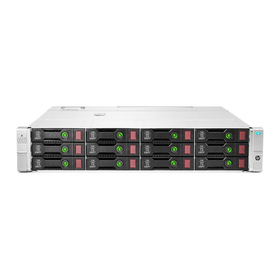
HPE D3600/3700 Disk Enclosure
Maintenance and Service Guide
Abstract
This guide is intended for users who maintain the HPE D3600/3700 Disk Enclosures. Some of the actions described are more
appropriate to Hewlett Packard Enterprise service specialists and require an Support login.
Part Number: 734754-001R
Published: November 2015
Edition: 2
Advertisement
Table of Contents

Related Manuals for HP D3600


Summary of Contents for HP D3600
- Page 1 Maintenance and Service Guide Abstract This guide is intended for users who maintain the HPE D3600/3700 Disk Enclosures. Some of the actions described are more appropriate to Hewlett Packard Enterprise service specialists and require an Support login. Part Number: 734754-001R...
- Page 2 © Copyright 2014, 2015 Hewlett Packard Enterprise Development LP The information contained herein is subject to change without notice. The only warranties for Hewlett Packard Enterprise products and services are set forth in the express warranty statements accompanying such products and services. Nothing herein should be construed as constituting an additional warranty.
-
Page 3: Table Of Contents
Contents 1 Introduction......................5 Hardware components..........................5 2 Removal and replacement procedures...............6 Required tools............................6 Required items............................6 Safety precautions..........................6 General precautions........................6 Preventing electrostatic discharge....................7 Symbols on equipment........................7 Warning and caution messages......................9 Precautions for maintaining and servicing products..............10 Power cords...........................11 Power supplies..........................11 Powering off disk enclosures......................11 Powering on............................12 Before powering on........................12 Power on procedures........................12... - Page 4 Compromised fault tolerance......................33 Factors to consider before replacing disk drives................33 Automatic data recovery (rebuild)....................34 Time required for a rebuild.......................34 Failure of another drive during rebuild..................35 Handling disk drive failures......................35 I/O module error codes........................36 4 Component identification...................40 5 Technical specifications..................42 Physical specifications........................42 Power and environmental specifications....................42 Acoustic noise levels..........................42 6 Support and other resources................44...
-
Page 5: Introduction
The HPE 12Gb SAS disk enclosures are available in two models: D3600: supports up to 12 Large Form Factor (LFF) SAS drives for a maximum capacity of 7.2 TB with 600GB SAS drives or 48 TB with 4 TB SAS MDL or 4TB SATA MDL drives. -
Page 6: Removal And Replacement Procedures
2 Removal and replacement procedures Required tools The following items are required for some procedures: T-8 Torx screwdriver T-10 Torx screwdriver T-15 Torx screwdriver Phillips screwdriver Required items Items required for installation include the following, some of which ship with the disk enclosure: Rack mounting kit Disk enclosure Disk drives and drive blanks... -
Page 7: Preventing Electrostatic Discharge
The product has been dropped or damaged. The product does not operate normally when you follow the operating instructions. To reduce the risk of personal injury or damage to the product: Place the product away from radiators, heat registers, stoves, amplifiers, or other products that produce heat. - Page 8 Removal and replacement procedures...
-
Page 9: Warning And Caution Messages
Warning and caution messages WARNING! To reduce the risk of personal injury or damage to equipment, heed all warnings and cautions throughout the installation instructions. WARNING! To reduce the risk of personal injury or damage to the equipment, be sure that: The leveling jacks are extended to the floor. -
Page 10: Precautions For Maintaining And Servicing Products
CAUTION: Always be sure that equipment is properly grounded and that you follow proper grounding procedures before beginning any installation procedure. Improper grounding can result in ESD damage to electronic components. For more information, see “Preventing electrostatic discharge” (page 7) CAUTION: When performing non-hot-plug operations, you must power down the server blade and/or the system. -
Page 11: Power Cords
Power cords To reduce the risk of electric shock or damage to the equipment: Use an approved power cord. If you have questions about the type of power cord to use, contact your Hewlett Packard Enterprise authorized service provider. If you have not been provided with a power cord for your product or for any AC-powered option intended for your product, purchase a power cord that is approved for use in your country. -
Page 12: Powering On
Powering on After disk enclosures are physically installed and cabled, power up all devices and verify that they are operating properly. Before powering on Observe the following best practices before powering on the enclosure for the first time: Complete the server, controller, or controller enclosure installation. For more information, see the server, controller, or controller enclosure user documents. -
Page 13: Verifying The Operating Status Of The Disk Enclosures
Verifying the operating status of the disk enclosures To verify that the disk enclosures and disk drives are operating properly, view the enclosure and disk drive LEDs and compare them with the patterns described in the following table. If LED patterns are not as expected, check cable connections between the devices, check the availability of your power source, review the installation procedures, and remove and reinsert the module. -
Page 14: I/O Module Leds
I/O module LEDs Indicator Startup condition Operating condition Fault conditions 1. Port Link Blinking or solid green 2. Port Error Solid amber 3. 7–segment display A number, representing the box number, or an error/warning code. 4. UID Blue 5. Health Blinking green Solid green 6. -
Page 15: Hard Drive Blanks
Indicator Status Definition 1 Locate Solid blue The drive is being identified by a host application. 2. Activity ring Rotating green Drive activity. No drive activity. 3. Do not remove Solid white Do not remove the drive. Removing the drive causes one or more of the logical drives to fail. -
Page 16: Disk Drive Guidelines
Disk drive guidelines CAUTION: Follow industry-standard practices when handling disk drives. Internal storage media can be damaged when drives are shaken, dropped, or roughly placed on a work surface. When installing a disk drive, press firmly to make sure the drive is fully seated in the drive bay and then close the latch handle. -
Page 17: Removing And Replacing I/O Cables
If you are replacing a disk drive, refer to “Removing a drive” (page 16) Unlatch and swing out the latch handle on the drive. Then, slide the drive into the bay (1), pressing firmly on the drive to seat it. Close the latch handle (2), pressing firmly until it locks in place. -
Page 18: Removing And Replacing The I/O Module
Replace the cable(s). Confirm basic communication using LEDs See “Verifying the operating status of the disk enclosures” (page 13). Removing and replacing the I/O module Unplug the two cables from the back panel of the I/O module. See “Removing and replacing I/O Cables”... -
Page 19: Removing And Replacing The Fan Module
Press the latch (1) and slide module out (2). Slide new power supply into the enclosure bay until it clicks into place. Replace the power cable. Confirm that the system is in normal state. See “Verifying the operating status of the disk enclosures”... - Page 20 Confirm that the system is in normal state. See “Verifying the operating status of the disk enclosures” (page 13). Removal and replacement procedures...
-
Page 21: Removing And Replacing The Fan Control Card
Removing and replacing the fan control card This operation is performed after Hewlett Packard Enterprise Support determines that the enclosure is the source of the issue and requests the fan control card to be replaced WARNING! Check to make sure data on the drives is backed up Back up data if required. Unplug the power cables. -
Page 22: Removing And Replacing The Enclosure
16. Replace the fan modules. See “Removing and replacing the fan module” (page 19) 17. Replace the I/O module cables. See “Removing and replacing the I/O module” (page 18) 18. Replace the power cables. 19. Apply power to the enclosure and confirm the system is powered on. See “Verifying the operating status of the disk enclosures”... -
Page 23: Removing And Replacing The Power Distribution Board
18. Replace power cables and connect the cables to a live power source. 19. Confirm system is powered on and that it is operating normally. See “Verifying the operating status of the disk enclosures” (page 13) Removing and replacing the Power Distribution Board This operation is performed after Support determines that the enclosure is the source of the issue and recommends that the Power Distribution Board be replaced. -
Page 24: Removing And Replacing The Uid-Health Module
Removing and replacing the UID-health module This operation is performed after Support determines that the UID-health module is the source of the issue and requests the module be replaced WARNING! Check to make sure data on the drives is backed up. Back up data if required Unplug the power cables. -
Page 25: Removing And Replacing The Enclosure Backplane
14. Tighten the retaining screws. See “Removing and replacing the enclosure” (page 22) 15. Replace the fan modules. See “Removing and replacing the fan module” (page 19). 16. Replace the I/O module cables. See “Removing and replacing the I/O module” (page 18) 17. - Page 26 NOTE: Depending on whether the drive cage is for LFF or SFF drives, the screws are in slightly different locations. 12. Slide the drive cage toward the front of the enclosure and lift free of the enclosure. 13. Remove the two T-15 screws attaching the back plane to the drive cage. 14.
-
Page 27: Installing The Rail Kit
Installing the rail kit The disk enclosure can be installed into most standard server racks. To verify that your rack is supported for use with the disk enclosure, see the QuickSpecs for the disk enclosure at the website: http://www.hpe.com/products/quickspecs. CAUTION: Install disk drives in the enclosures only after mounting the enclosures in the rack. -
Page 28: Procedures
Procedures Position left and right rack rails at the desired 'U' position in the rack, adjusting the rails to fit the rack, as needed. Front and Rear bottom edge of rails must align with the bottom of EIA boundary in the lowermost 'U' NOTE: Rails are marked L and R with an arrow indicating the direction in which the rail... - Page 29 Attach rear hold down brackets by sliding the tab with the arrow pointed forward (1) into the corresponding slot on the left and right side of the rear of the chassis. Use the black headed thumb screw to secure tightly to the rail (2). Installing the rail kit...
-
Page 30: Troubleshooting
3 Troubleshooting If the enclosure does not initialize IMPORTANT: After a power failure, the system automatically returns to the On state when A/C power is restored, except in the following cases: If both power supplies are damaged. If there is a single power supply in the system, and it is damaged. Ensure that power has been applied to the enclosure. -
Page 31: Is The Enclosure Rear Fault Led Amber
Is the enclosure rear fault LED amber? Answers Possible Reasons Actions Functioning properly. No action required Rear power and UID module might Be sure that the rear power and UID not be inserted properly, might have module is undamaged and is fully a damaged connector, or might have seated. -
Page 32: Is The Fan Led Amber
Is the fan LED amber? Answers Possible Reasons Actions Functioning properly. No action required Fan might not be inserted properly, Be sure that the fan is undamaged might have a damaged connector, or and is fully seated. might have failed. Contact an authorized service provider for assistance. -
Page 33: Recognizing Disk Drive Failure
Recognizing disk drive failure In an Hewlett Packard Enterprise enclosure, a steadily glowing fault LED indicates that a disk drive has failed. Other indications of failed disk drives are as follows: ACU represents failed drives with a distinctive icon. HPE SIM can detect failed drives remotely across a network. (For more information about SIM, see the documentation on the Management CD.) ADU lists all failed drives. -
Page 34: Automatic Data Recovery (Rebuild)
To minimize the likelihood of fatal system errors, take these precautions when removing failed drives: Do not remove a degraded drive if any other drive in the array is offline (the online LED is off). In this situation, no other drive in the array can be removed without data loss. Exceptions: ◦... -
Page 35: Failure Of Another Drive During Rebuild
System performance is affected during the rebuild, and the system is unprotected against further drive failure until the rebuild has finished. Therefore, replace drives during periods of low activity when possible. CAUTION: If the Online LED of the replacement drive stops blinking and the amber fault LED glows, or if other drive LEDs in the array go out, the replacement drive has failed and is producing unrecoverable disk errors. -
Page 36: I/O Module Error Codes
I/O module error codes This table describes the possible error codes appearing in the 7–segment display on the back panel of the I/O module. For information on the location of the 7–segment display, see “I/O module LEDs” (page 14) Error Type Error Code Error Detail Recommended Action... - Page 37 Error Type Error Code Error Detail Recommended Action Expander firmware version mismatch with Expander firmware version in partner I/O module Expander firmware image error Expander firmware version mismatch with ESP firmware version in own I/O module SAS Cable SAS cable hardware 1.
- Page 38 Error Type Error Code Error Detail Recommended Action System shutdown because of over temperature Power Supply Generic error in Power If a power supply module does not have a green LED Module Error Supply module 1 illuminated, verify that it is correctly cabled to a power source.
- Page 39 Error Type Error Code Error Detail Recommended Action Absence of the Fan Verify that the fan module is tightly inserted in the module 1 slot. If a fan module is missing, then insert a module in Absence of the Fan the empty slot.
-
Page 40: Component Identification
4 Component identification Component identification... - Page 41 Description CSR status 1. Chassis Bezel Ear Not a CSR part (part of drive cage) 2. Chassis Bezel Ear Not a CSR part (part of drive cage) 3. Drive Cage Not a CSR part 4. Backplane Mandatory 5. Fan module interconnect board Mandatory 6.
-
Page 42: Technical Specifications
5 Technical specifications Physical specifications Height/Width/Depth HPE D3600 LFF: 3.44 x 17.64 x 23.54 in (8.7 x 44.8 x 59.8 cm) HPE D3700 SFF: 3.44 x 17.64 x 21.48 in (8.7 x 44.8 x 54.6 cm) Weight No disk drives: 38 lb (17.2 kg) D3700 SFF fully populated with SFF disk drives: 54.90 lb (24.9 kg) - Page 43 Operating Acoustic Noise (sound power) LWAd= 7.0 B Operating Acoustic Noise (sound pressure) LpAm - 53 dBA Acoustic noise levels...
-
Page 44: Support And Other Resources
Hewlett Packard Enterprise Support Center More Information on Access to Support Materials page: www.hpe.com/support/AccessToSupportMaterials IMPORTANT: Access to some updates might require product entitlement when accessed through the Hewlett Packard Enterprise Support Center. You must have an HP Passport set up with relevant entitlements. Websites Website Link Hewlett Packard Enterprise Information Library www.hpe.com/info/enterprise/docs... -
Page 45: Customer Self Repair
Subscription Service/Support Alerts www.hpe.com/support/e-updates Software Depot www.hpe.com/support/softwaredepot Customer Self Repair www.hpe.com/support/selfrepair Insight Remote Support www.hpe.com/info/insightremotesupport/docs Serviceguard Solutions for HP-UX www.hpe.com/info/hpux-serviceguard-docs Single Point of Connectivity Knowledge (SPOCK) www.hpe.com/storage/spock Storage compatibility matrix Storage white papers and analyst reports www.hpe.com/storage/whitepapers Customer self repair Hewlett Packard Enterprise customer self repair (CSR) programs allow you to repair your product. -
Page 46: A Warranty And Regulatory Information
A Warranty and regulatory information For important safety, environmental, and regulatory information, see Safety and Compliance Information for Server, Storage, Power, Networking, and Rack Products, available at www.hpe.com/support/Safety-Compliance-EnterpriseProducts. Warranty information HPE ProLiant and x86 Servers and Options www.hpe.com/support/ProLiantServers-Warranties HPE Enterprise Servers www.hpe.com/support/EnterpriseServers-Warranties HPE Storage Products www.hpe.com/support/Storage-Warranties... -
Page 47: Turkey Rohs Material Content Declaration
Local representative information Kazakh: Russia: Belarus: Kazakhstan: Manufacturing date: The manufacturing date is defined by the serial number. CCSYWWZZZZ (serial number format for this product) Valid date formats include: YWW, where Y indicates the year counting from within each new decade, with 2000 as the starting point;...
Need help?
Do you have a question about the D3600 and is the answer not in the manual?
Questions and answers