HP StorageWorks Reference Manual
1u rackmount tape enclosure
Hide thumbs
Also See for StorageWorks:
- User manual (204 pages) ,
- Installation manual (106 pages) ,
- Getting started manual (52 pages)
Table of Contents
Advertisement
Quick Links
Reference
Guide
hp StorageWorks
1U Rackmount Tape Enclosure
First Edition (August 2004)
Part Number: A7443-96001
This guide is to be used as step-by-step installation instructions and reference information for
operation, troubleshooting, and future upgrades of the HP StorageWorks 1U Rackmount Tape
Enclosure.
Advertisement
Table of Contents

Related Manuals for HP StorageWorks


Summary of Contents for HP StorageWorks
- Page 1 StorageWorks 1U Rackmount Tape Enclosure First Edition (August 2004) Part Number: A7443-96001 This guide is to be used as step-by-step installation instructions and reference information for operation, troubleshooting, and future upgrades of the HP StorageWorks 1U Rackmount Tape Enclosure.
- Page 2 Hewlett-Packard. The information contained in this document is subject to change without notice. The only warranties for HP products and services are set forth in the express warranty statements accompanying such products and services. Nothing herein should be construed as constituting an additional warranty.
-
Page 3: Table Of Contents
HP authorized reseller ........ - Page 4 Contents Tools required............. 26 Installing a second tape drive .
-
Page 5: About This Guide
About This Guide About this Guide Overview About this Guide This reference guide provides information to help you: Understand the components and use of the 1U Rackmount Tape Enclosure Install or replace tape drives in the enclosure Install the tape enclosure in a rack Intended audience This book is intended for use by system administrators or technicians who are experienced with the following:... -
Page 6: Document Conventions And Symbols
Monospace font directory names, and system responses (output and messages) Blue underlined sans serif font text Web site addresses (http://www.hp.com) WARNING: Indicates that failure to follow directions in the warning could result in bodily harm or death. Caution: Indicates that failure to follow directions could result in damage to equipment or data. -
Page 7: Equipment Symbols
About this Guide Equipment symbols The following equipment symbols may be found on hardware for which this guide pertains. They have the following meanings: Any enclosed surface or area of the equipment marked with these symbols indicates the presence of electrical shock hazards. Enclosed area contains no operator serviceable parts. -
Page 8: Rack Stability
About this Guide Rack stability Rack stability protects personnel and equipment. WARNING: To reduce the risk of personal injury or damage to the equipment, be sure that: The leveling jacks are extended to the floor. The full weight of the rack rests on the leveling jacks. In single rack installations, the stabilizing feet are attached to the rack. -
Page 9: Getting Help
Operating system type and revision level Detailed, specific questions HP storage web site The HP web site has the latest information on this product, as well as the latest http://www.hp.com/country/us/eng/prodserv/ drivers. Access storage at: storage.html. From this web site, select the appropriate product or solution. - Page 10 About this Guide 1U Rackmount Tape Enclosure Reference Guide...
-
Page 11: Introduction
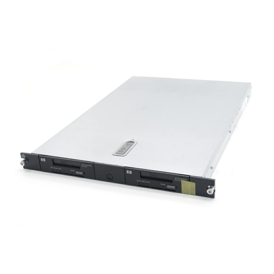
Introduction The HP StorageWorks 1U Rackmount Tape Enclosure is a rack-mountable storage system capable of holding up to two half-height 5.25 inch SCSI tape drives. It is compatible with HP 7000, 9000, & 10000 series, HP Rack System/E, HP AlphaServer, and other standard 19 inch racks. -
Page 12: Standard Features
It will not automatically power up. Supported hardware options For a list of currently supported SCSI controllers and other hardware options, such as tape drives and media, visit the HP web site at: http://h18006.www1.hp.com/storage/tapestorage.html 1U Rackmount Tape Enclosure Reference Guide... -
Page 13: Tape Enclosure Components
Introduction Tape enclosure components 15101 Figure 2: Tape enclosure front panel components Tape drive Expansion drive bay Power switch/LED 15102 Figure 3: Tape enclosure rear panel components AC power connector LVD/SE Wide SCSI connector(s) SCSI ID switch(es) 1U Rackmount Tape Enclosure Reference Guide... - Page 14 Introduction 15108 Figure 4: Tape enclosure internal components Tape drive Tape drive blank Power supply Fan assemblies (2) Internal LVD/SE Wide SCSI cables (2) SCSI ID switch cables (2) 1U Rackmount Tape Enclosure Reference Guide...
-
Page 15: Rack Installation
Rack Installation Rail mounting kit The rack rails supplied with the 1U rackmount tape enclosure can be used to install the unit in racks that have round, square, or threaded holes in the vertical mounting bars. The rails will fit racks with 23 - 34 inches (58 - 86 cm) separation between the front and rear vertical mounting bars. -
Page 16: Tools Required
Rack Installation Tools required If you are installing the tape enclosure in a rack with unmarked holes in the vertical mounting bars the following items will make the rack installation easier: Pencil Tape measure If you are installing the tape enclosure in a rack with threaded holes in the vertical mounting bars you will need the following tool: 3/16”... -
Page 17: Installing The Component Rails
Rack Installation It is important to install rack components level. To ensure that the 1U Caution: tape enclosure is installed correctly it may be necessary to measure the height of the correct mounting holes in the front and rear vertical mounting bars. Installing the component rails Component rails are the inner portion of the rack rail system that attached to the tape enclosure. -
Page 18: Installing The Rack Rails
Rack Installation Installing the rack rails Installation procedures vary depending on the rack type. The rails are shipped ready for installation in racks with round or square holes. If the rails are to be installed in racks with 10-32 threaded holes, the mounting pins must first be removed. - Page 19 Rack Installation 2. Extend the rack rails past the rear vertical mounting bar and insert the pins in the mounting bracket into the previously marked holes in the rack. See Figure 8. The rack rails will lock securely into place when the end of the rails are pushed forward.
-
Page 20: Installation In Racks With 10-32 Threaded Holes
Rack Installation Installation in racks with 10-32 threaded holes For installation in racks with 10-32 threaded holes in the vertical mounting bars the pins supplied on the rails must be removed. The rails will be attached with user-supplied 10-32 x.375 screws. 1. - Page 21 Rack Installation 15119 Figure 10: Installing the rack rails in front of rack 3. Extend the rack rails past the rear vertical mounting bars and attach the back mounting plate of each outer rail to the rack using four 10-32 screws in the previously marked holes.
-
Page 22: Completing The Installation
Rack Installation Completing the installation 1. Extend the stabilizing feet if provided on your rack. 2. Extend the left and right rack rails from the front of the rack. 3. Align the rear of the component rails on the tape enclosure with the front ends of the rack rails, then slide the unit fully into the rack. - Page 23 Rack Installation Refer to“Internal cable configurations” on page 33 for details on configuring Note: one or two SCSI buses in the enclosure. 6. Plug the external SCSI cable from the SCSI controller to the appropriate connector(s) on the rear panel of the enclosure. See Figure Note: Daisy-chaining of two or more 1U Rackmount Tape Enclosures is not supported.
- Page 24 Rack Installation 15125 Figure 14: Install the cable support clips 9. Turn on the power to the tape enclosure with the front panel power button. 1U Rackmount Tape Enclosure Reference Guide...
-
Page 25: Tape Drive Installation And Replacement
Tape Drive Installation and Replacement This chapter describes installation or replacement of a tape drive into the HP StorageWorks 1U Rackmount Tape Enclosure. This chapter covers the following topics: Setting SCSI IDs, page 25 Tools required, page 26 Installing a second tape... -
Page 26: Tools Required
Tape Drive Installation and Replacement The SCSI IDs for the tape drives in the 1U rackmount tape enclosure can be set in one of two ways: 1. The enclosure has two remote SCSI ID switches, one for each drive, on the rear panel. - Page 27 Tape Drive Installation and Replacement 5. Remove the top access panel by turning the latch lock 1 counterclockwise, lifting the latch 2, and sliding the panel back 3. See Figure 15107 Figure 15: Removing the top access panel 6. Remove the tape drive blank by pulling up the spring-loaded button 1 on the rear of the right mounting rail.
- Page 28 Tape Drive Installation and Replacement 7. Remove the left and right mounting brackets from the tape drive blank by removing two screws from each side. See Figure 17. Save the screws and mounting brackets for use in the next step. 15110 Figure 17: Removing the mounting brackets 8.
- Page 29 Tape Drive Installation and Replacement 9. If you are not using the remote SCSI ID switch on the tape enclosure, set the SCSI ID with jumpers on the back of the new drive. Refer to the documentation for your tape drive for information about setting the SCSI ID. 10.
- Page 30 Tape Drive Installation and Replacement To prevent possible data errors, when there is only one drive on a Caution: SCSI bus that drive must be connected to the SCSI port closest to the terminator. 12. Attach the power cable 1, SCSI ID cable 2 (if used), and SCSI data cable 3 to the back of the drive.
- Page 31 Tape Drive Installation and Replacement 13. Replace the top cover by placing in on top of the enclosure 1, engaging all the pins into slots in both sides of the enclosure as well as the central pin in the latch. Push the latch down flush with the top 2 and turn the lock clockwise 3 to prevent accidental opening.
- Page 32 Tape Drive Installation and Replacement 17. If used reattach the cable bundle to the cable support clips at the rear of the rack. See Figure 15125 Figure 22: Cable support mechanism 18. Retract the stabilizing feet if provided on the rack. 19.
-
Page 33: Internal Cable Configurations
Tape Drive Installation and Replacement Internal cable configurations The 1U Tape Enclosure supports operation of two tape drives on either 1 or 2 SCSI buses. Two internal 2-port SCSI cables are installed in the enclosure, so completing the drive installations just a matter of connecting the correct SCSI port according to your configuration. -
Page 34: Two Drives On Two Scsi Buses
Tape Drive Installation and Replacement Each SCSI device on the same SCSI bus must have a unique SCSI ID. Be sure that Note: the SCSI ID is different for each drive and that neither is set to SCSI ID 7 Two drives on two SCSI buses Use the configuration shown in Figure 24... -
Page 35: Replacing A Tape Drive
Tape Drive Installation and Replacement Replacing a tape drive Caution: If you are returning a failed tape drive, DO NOT return the drive mounting brackets. Caution: To avoid damaging the equipment due to electrostatic discharge, be sure to review and practice the procedures in Appendix B before handling the tape drives. - Page 36 Tape Drive Installation and Replacement 5. Remove the top panel by turning the latch lock 1 counter-clockwise, lifting the latch 2, sliding the panel back 3, and lifting it from the enclosure. See Figure 15107 Figure 25: Removing the top panel Caution: To avoid the possibility of damaging the tape drive, do not pull the drive using the front bezel.
- Page 37 Tape Drive Installation and Replacement 15112 Figure 26: Removing the tape drive 7. Disconnect the SCSI data, SCSI ID (if used), and power cables from the back of the drive. 8. Remove the left and right mounting brackets from the tape drive by removing two screws from each side.
- Page 38 Tape Drive Installation and Replacement 9. Install the left and right mounting brackets to the sides of the new tape drive using the screws removed in step 8. See Figure 15127 Figure 28: Installing the drive mounting brackets 10. If you are not using the remote SCSI ID switch on the tape enclosure, set the SCSI ID with jumpers on the back of the new drive.
- Page 39 Tape Drive Installation and Replacement Make sure that all of the posts are engaged into their respective slots in the drive Note: mounting rails. 15106 Figure 29: Installing the tape drive 13. Attach the power cable 1, SCSI data cable 3, and SCSI ID cable 2 (if used) removed in step 7.
- Page 40 Tape Drive Installation and Replacement To avoid injury from rotating fan blades, do not attempt to WARNING: operate the tape enclosure with the top removed. Caution: When reinstalling the top cover, be sure the latch is fully engaged and is flush with the cover to avoid interference with devices installed above the 1U tape enclosure in the rack.
- Page 41 Tape Drive Installation and Replacement 15125 Figure 32: Cable support mechanism 17. Retract the stabilizing feet if used on your rack. 18. Turn on the power to the tape enclosure with the front panel power button. Tape drive replacement is complete. 1U Rackmount Tape Enclosure Reference Guide...
-
Page 42: Troubleshooting
Tape Drive Installation and Replacement Troubleshooting Use the following information to help solve problems that may develop while installing or replacing a tape drive. Table 2: Tape drive installation troubleshooting Problem Cause Solution Random data errors detected For installations with one tape Verify that tape drive is on tape drive drive on a SCSI bus, that drive... -
Page 43: A Regulatory Compliance Notices
Regulatory Compliance Notices Federal Communications Commission Notice Part 15 of the Federal Communications Commission (FCC) Rules and Regulations has established Radio Frequency (RF) emission limits to provide an interference-free radio frequency spectrum. Many electronic devices, including computers, generate RF energy incidental to their intended function and are, therefore, covered by these rules. -
Page 44: Class B Equipment
Regulatory Compliance Notices Class B Equipment This equipment has been tested and found to comply with the limits for a Class B digital device, pursuant to Part 15 of the FCC Rules. These limits are designed to provide reasonable protection against harmful interference in a residential installation. -
Page 45: Canadian Notice (Avis Canadien)
Regulatory Compliance Notices Hewlett-Packard Company P. O. Box 692000, Mail Stop 530113 Houston, Texas 77269-2000 Or, call 1-800- 652-6672 For questions regarding this FCC declaration, contact: Hewlett-Packard Company P. O. Box 692000, Mail Stop 510101 Houston, Texas 77269-2000 Or, call (281) 514-3333 To identify this product, refer to the part, series, or model number found on the product. -
Page 46: European Union Notice
Regulatory Compliance Notices European Union notice Products bearing the CE marking comply with the EMC Directive (89/336/EEC) and the Low Voltage Directive (73/23/EEC) issued by the Commission of the European Community and if this product has telecommunication functionality, the R&TTE Directive (1999/5/EC). Compliance with these directives implies conformity to the following European Norms (in parentheses are the equivalent international standards and regulations): EN 55022 (CISPR 22) - Electromagnetic Interference... -
Page 47: Bsmi Notice
Regulatory Compliance Notices BSMI notice Japanese notice Japanese power cord notice 1U Rackmount Tape Enclosure Reference Guide... -
Page 48: Korean Notices
Regulatory Compliance Notices Korean notices 1U Rackmount Tape Enclosure Reference Guide... -
Page 49: Electrostatic Discharge
Electrostatic Discharge To prevent damage to the system, be aware of the precautions you need to follow when setting up the system or handling parts. A discharge of static electricity from a finger or other conductor may damage system boards or other static-sensitive devices. -
Page 50: Grounding Methods
Electrostatic Discharge Grounding methods There are several methods for grounding. Use one or more of the following methods when handling or installing electrostatic-sensitive parts: Use a wrist strap connected by a ground cord to a grounded workstation or computer chassis. Wrist straps are flexible straps with a minimum of 1 megohm ±... -
Page 51: Specifications
Specifications Table 3: HP StorageWorkds 1U Rackmount Tape Enclosure Parameter English Metric Dimensions Height 1.75 in 4.44 cm Depth 25.25 in 64.1 cm Width 19.0 in 48.3 cm Weight (1 drive installed) 20 lb 9.07 kg Input power requirements Rated input voltage... - Page 52 Specifications 1U Rackmount Tape Enclosure Reference Guide...
-
Page 53: Index
HP help, obtaining capacity compatibility authorized reseller conventions storage web site document technical support equipment symbols text symbols internal components document conventions prerequisites prerequisites related documentation rack stability, warning rear panel components electrostatic discharge 49,... - Page 54 Index tape drives warning installing rack stability technical support, HP symbols on equipment text symbols web sites HP storage 1U Rackmount Tape Enclosure Reference Guide...
Need help?
Do you have a question about the StorageWorks and is the answer not in the manual?
Questions and answers