Table of Contents
Advertisement
Quick Links
Kingfisher International
____________________________________________________________________________
_______________________________________________________
USER MANUAL
KI 6700 HAND HELD OTDR
Multifunctional optical measuring device
Issue 1, 2010
_________________________________________________________________
User Manual – KI6700 Hand Held OTDR
Issue 1
Page 1 of 96
Advertisement
Table of Contents

Related Manuals for Kingfisher KI 6700


Summary of Contents for Kingfisher KI 6700
- Page 1 Kingfisher International ____________________________________________________________________________ _______________________________________________________ USER MANUAL KI 6700 HAND HELD OTDR Multifunctional optical measuring device Issue 1, 2010 _________________________________________________________________ User Manual – KI6700 Hand Held OTDR Issue 1 Page 1 of 96...
- Page 2 The contents of this publication are subject to change without notice. All efforts have been made, to ensure the accuracy of this publication. Notwithstanding, Kingfisher International Limited does not assume responsibility for any errors nor for any consequences arising from any errors in this publication.
-
Page 3: Table Of Contents
Technical specifications of the visual fault locator ........16 2.5 General technical specifications of the KI 6700 ........17 KI 6700 PACKAGE ................... 18 DESIGN & PRINCIPLE OF OPERATION OF THE KI 6700 ......19 4.1 KI 6700 Design ..................19 4.2 ... - Page 4 Work with an OTDR in remote control mode ..........77 7.8.1 Software on a CD ..................... 77 7.8.2 Controlling KI 6700 with the help of a PC: performing measurements .... 83 7.8.3 Software updating .................... 84 WORK WITH THE LIGHT SOURCE & OPTICAL POWER METER ....86 ...
-
Page 5: Application
When configured for SMF operation, the KI6700 can be used as a laser light source When optioned as an Optical Power Meter the KI 6700 can be used for measuring optical power. When optioned with a Visual Fault Locator (VFL) the KI 6700 can be used for patch cord tracing and detection of fibre breaks in bare fibre, 900 µm and... - Page 6 Kingfisher International ____________________________________________________________________________ 1.4 KI 6700 optional features Possible KI 6700 configuration is defined according to Table 1.1 below. Visual Fault Light source Optical power meter Locator (VFL) ☻ Single-mode OPTION OPTION OTDR Multimode OTDR OPTION OPTION ☻ OPTION Combined OTDR...
- Page 7 Kingfisher International ____________________________________________________________________________ Possible OTDR configuration is defined in accordance with Table 1.2 below. Dynamic range / Multimode fiber Wavelength dead zone core diameter 1310 nm, Modification 1 1490 nm, 1550 nm, Modification 2 Single-mode 1625 nm: − OTDR Modification 3...
- Page 8 Kingfisher International KI 6700 / X - X - X X X X - X X - X X - X X MODEL OTDR OPTICAL CONNECTOR MM 1 = FC OTDR 1 2 = SC 3 = ST 1= SMF OTDR X = N/A 2= MM OTDR 3= Combined SMF & MM OTDR VISUAL FAULT LOCATOR 1 =...
-
Page 9: Technical Specifications
∆L = ± (0.5 + dL + 5⋅10 ⋅L), m o where dL – distance resolution (0.16; 0.32; 0.64; 1.3; 2.5; 5.1; 3.8 and 7.6 m); o L - measurable distance, m; _________________________________________________________________ User Manual – KI 6700 Hand Held OTDR Issue 1 Page 9 of 96... - Page 10 Dead zone values are specified at the following conditions: − minimum pulsewidth, − reflectance not more than -40 dB, − "High resolution" mode is turn on. _________________________________________________________________ User Manual – KI 6700 Hand Held OTDR Issue 1 Page 10 of 96...
- Page 11 Pulsewidth, ns Reflectance, dB dead zone, m dead zone, m ≤ -40 Table 2.3 - Dynamic range & dead zone of the SMF OTDR (modification 2) _________________________________________________________________ User Manual – KI 6700 Hand Held OTDR Issue 1 Page 11 of 96...
- Page 12 Pulsewidth, ns Reflectance, dB dead zone, m dead zone, m ≤ -40 13.0 Table 2.5- Dynamic range & dead zone of the SMF OTDR (modification 4) _________________________________________________________________ User Manual – KI 6700 Hand Held OTDR Issue 1 Page 12 of 96...
- Page 13 Attenuation Pulsewidth, ns Reflectance, dB dead zone, m dead zone, m ≤ -40 Table 2.6 - Dynamic range & dead zone of the multimode OTDR _________________________________________________________________ User Manual – KI 6700 Hand Held OTDR Issue 1 Page 13 of 96...
- Page 14 Table 2.7 - Dynamic range & dead zone of the combined OTDR (SMF and multimode OTDR) 2.1.7 Loss accuracy at temperature of (20 ± 5) °С: ∆α = ± (0.04⋅α) dB, where α – attenuation value. _________________________________________________________________ User Manual – KI 6700 Hand Held OTDR Issue 1 Page 14 of 96...
-
Page 15: Technical Specifications Of The Light Source
2.2.3 Warm-up time – not more than 15 minutes. 2.2.4 Optical connector of the single-mode OTDR is at the same time the connector of the light source. _________________________________________________________________ User Manual – KI 6700 Hand Held OTDR Issue 1 Page 15 of 96... -
Page 16: Technical Specifications Of The Optical Power Meter
2.4.3 Output power – 0.5 to 0.9 mW. 2.4.4 Operation mode – continuous and pulsed. 2.4.5 Universal 2.5 mm adaptor is used for optical fiber connection. _________________________________________________________________ User Manual – KI 6700 Hand Held OTDR Issue 1 Page 16 of 96... -
Page 17: General Technical Specifications Of The Ki 6700
• Battery operational life – 5~7hours; • Display: 4.3” LCD. • KI 6700 control is performed with a keypad. • Internal memory: up to 500 traces can be saved in the device memory. • External memory: connector for USB flash memory. -
Page 18: Ki 6700 Package
Kingfisher International _______________________________________________________________________ KI 6700 PACKAGE KI 6700 package is presented in table 3.1 Name Notes Multifunction optical measuring device KI 6700 AC/DC adaptor Input:100V∼- 240 V∼; output: 12V=/ 700mA Interface cable USB-А - USB-В Connection with a PC Storage battery... -
Page 19: Design & Principle Of Operation Of The Ki 6700
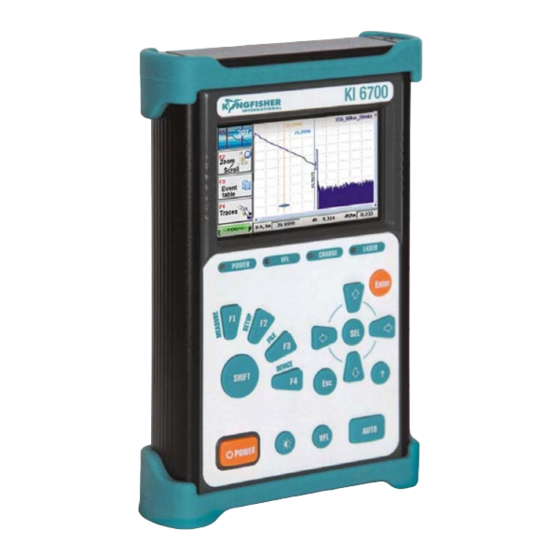
Kingfisher International _______________________________________________________________________ DESIGN & PRINCIPLE OF OPERATION OF THE KI 6700 KI 6700 Design KI 6700 is incased into a small size rectangular body. General view of the KI 6700 is shown in Figure 4.1. Figure 4.1 _________________________________________________________________ User Manual – KI 6700 Hand Held OTDR... - Page 20 • Optional Optical Power Meter • Optional Visual Fault Locator (VFL) • Plug Pack AC/DC Power Supply. • Integral rechargeable battery. On the front panel of the KI 6700 there are: − 4.3” display − Control buttons; − LED indicators −...
- Page 21 Kingfisher International _______________________________________________________________________ Figure 4.2 shows the KI 6700 block diagram. Figure 4.2 Processing module provides control of optical measuring devices, display and control buttons. The internal voltage converter transforms the external input voltage (or built-in storage battery voltage) for feeding device modules.
-
Page 22: Otdr Principle Of Operation
• Optical coupler (OC) serving for inputting pulses into the optical fiber under test and passing back scattering signals to the Rx. _________________________________________________________________ User Manual – KI 6700 Hand Held OTDR Issue 1 Page 22 of 96... - Page 23 Tx – optical transmitter ОC – optical coupler Rx – optical receiver VC – voltage converter ОF – optical fiber under test OOC – output optical connector _________________________________________________________________ User Manual – KI 6700 Hand Held OTDR Issue 1 Page 23 of 96...
-
Page 24: Principle Of Light Source Operation
In this way the whole optical fiber is measured, registered and shown. Principle of light source operation The light source in the KI 6700 is realised only in case a single-mode OTDR is available. The light source is designed for generating continuous optical radiation. It uses the same laser diodes and optical splitter as in OTDR. - Page 25 Tx – optical transmitter ОC – optical coupler Rx – optical receiver PD – photodiode LPSC – laser power stabilisation circuit OOC – output optical connector _________________________________________________________________ User Manual – KI 6700 Hand Held OTDR Issue 1 Page 25 of 96...
-
Page 26: Principle Of Optical Power Meter Operation
Visual fault locator The KI 6700 device may have an inbuilt source of visible radiation – a laser diode with 650 nm wavelength (red light) and a single mode output. It is designed for detecting optical fiber faults near optical ports. If an optical fiber is broken or is strongly bent, the light will escape at this location. -
Page 27: Marking And Sealing
− "VFL" – visual fault locator optical port (if available in the device). On the back panel of the KI 6700 there is a label with the following information: − the type and configuration of the device;... -
Page 28: Ki 6700 Operation
Switching KI 6700 On/Off 6.2.1 The KI 6700 is switched ON by prolonged pressing the “POWER” button. The indicating LED “POWER” on the front panel lights up. 6.2.2 The device is switched OFF by a prolonged pressing the “POWER”... -
Page 29: Designation Of Panel Buttons
_______________________________________________________________________ 6.2.3 Switching visual fault locator is performed by prolonged pressing the “VFL” button. The VFL can be switched ON/OFF irrespective of KI 6700 being switched on or not. VFL can work in continuous and pulse mode. The mode is chosen by a short pressing the “VFL”... - Page 30 Choosing values from the list and for editing parameters Buttons for choosing functions in the window, for choosing data line , activating sub-modes, markers moving Activating “Help” function Table 6.1 _________________________________________________________________ User Manual – KI 6700 Hand Held OTDR Issue 1 Page 30 of 96...
-
Page 31: Choosing Ki 6700 Functions
− OTDR (always available); − OPTICAL TESTER (this inscription indicates that the KI 6700 also contains an optical power meter and a light source); − OPTICAL POWER METER (this inscription indicates that the KI 6700 contains only an optical power meter);... -
Page 32: Setting Up Ki 6700
6.4.3 In remote control mode the OTDR works under the control of the external software installed on the PC. KI 6700 REFLECT Software is supplied on a CD together with the device. The work with this Software is described in “KI 6700 REFLECT Software”... - Page 33 Figure 6.5 shows the window for setting the screen lighting. Figure 6.5 _________________________________________________________________ User Manual – KI 6700 Hand Held OTDR Issue 1 Page 33 of 96...
- Page 34 Figure 6.6 Quitting the window is performed by pressing the button , the changes being saved, or by button without saving the changes. _________________________________________________________________ User Manual – KI 6700 Hand Held OTDR Issue 1 Page 34 of 96...
-
Page 35: Work With The Otdr
F1, F2, F3, F4 button on the front panel of the device. Beneath the buttons you will see the indicator of battery charge state. The red strip on the battery signals the necessity of charging. _________________________________________________________________ User Manual – KI 6700 Hand Held OTDR Issue 1 Page 35 of 96... -
Page 36: Main Menu Buttons Functions
– opens the window “Measuring parameters” (see 7.3). F3→ – opens the window with the list of files saved in the memory of the device for saving/opening traces (see 7.5). _________________________________________________________________ User Manual – KI 6700 Hand Held OTDR Issue 1 Page 36 of 96... -
Page 37: Setting Up Measuring Parameters
“High resolution” is performed by button. Several wavelengths can be marked simultaneously. In this case the measurements will be performed at all chosen wavelengths one after another without interruption. _________________________________________________________________ User Manual – KI 6700 Hand Held OTDR Issue 1 Page 37 of 96... - Page 38 − press the button again. If a KI 6700 device contains a combined OTDR (for single and multi-mode optical fiber) the choice of single-mode OTDR wavelength (SM1310, SM 1550 etc.) automatically cancels the choice of multimode OTDR wavelengths (MM 850, MM1300) and vice versa.
- Page 39 (and, consequently, to its energy), but at the same time the space resolution of the OTDR becomes worse as the space length of the _________________________________________________________________ User Manual – KI 6700 Hand Held OTDR Issue 1 Page 39 of 96...
- Page 40 It will also result in transferring to the main OTDR program window (see 7.1.2 and 7.6). 7.3.1.6 Having set all the measurement parameters the user can F1→ immediately proceed to measuring pressing the button _________________________________________________________________ User Manual – KI 6700 Hand Held OTDR Issue 1 Page 40 of 96...
-
Page 41: Additional Measuring And Analysis Parameters
7.3.2.2 Passing from one window parameter to another is performed with the help of buttons , the choice of parameter – by the button.. Pressing the button activates the window for making changes, e.g. _________________________________________________________________ User Manual – KI 6700 Hand Held OTDR Issue 1 Page 41 of 96... - Page 42 Splice loss, LT – threshold of the event attenuation value, dB; events in which the attenuation exceeds the threshold value is shown in the Event Table (see 7.6.11 and 7.6.17). _________________________________________________________________ User Manual – KI 6700 Hand Held OTDR Issue 1 Page 42 of 96...
-
Page 43: Automatic Saving
7.3.3 Automatic saving 7.3.3.1 The program enables the automatic saving of measured traces into the KI 6700 memory immediately after the measurement completion. To use F2→ of this function, press the button in the window for additional measurement parameters (see Figure 7.4) –... - Page 44 The right part of the window is accessible only if the symbol √ is put in the line “Auto save”. _________________________________________________________________ User Manual – KI 6700 Hand Held OTDR Issue 1 Page 44 of 96...
-
Page 45: Measurement
− on the KI 6700 front panel LED indicator “LASER’ lights up. The measurement begun, only the new traces under measurement are shown on the screen, the previous traces remaining in the list of the window “Traces”... -
Page 46: Work With Files
The working field of the window consists of two parts. In the right part there is a list of folders and files with traces saved in the memory of the device _________________________________________________________________ User Manual – KI 6700 Hand Held OTDR Issue 1 Page 46 of 96... - Page 47 The movement from one button of the keyboard to another is performed with the help of the buttons . When you press the button the chosen letter or figure will be registered in the top field for _________________________________________________________________ User Manual – KI 6700 Hand Held OTDR Issue 1 Page 47 of 96...
- Page 48 The files can be opened by the software of other OTDR types if they support this format. 7.5.1.4 If the measuring was performed at several wavelengths simultaneously all the traces are saved as a group. They have the same _________________________________________________________________ User Manual – KI 6700 Hand Held OTDR Issue 1 Page 48 of 96...
- Page 49 Figure 7.10 will appear on the screen. Figure 7.10 When you press the button all the group will open, while pressing the button you will open only one chosen trace. _________________________________________________________________ User Manual – KI 6700 Hand Held OTDR Issue 1 Page 49 of 96...
-
Page 50: Window "File" − Additional Functions
7.5.2.3 To remove a file from the memory of the device, press the button F2→ . The dialog window will appear with a request to confirm - Figure7.12. _________________________________________________________________ User Manual – KI 6700 Hand Held OTDR Issue 1 Page 50 of 96... -
Page 51: Use Of A Removable Disk (Flash Memory)
For work with files, an external removable disk (flash memory) can be used. It is inserted into the USB-A port on the top panel of the KI 6700 device. A removable disk is matched with the folder Removable Disk which becomes accessible in the window with the list of files after the removable disk is installed. -
Page 52: Work With Traces
In the data line at the bottom of the screen you will see the parameters of the trace corresponding to the markers’ position and measurement mode. _________________________________________________________________ User Manual – KI 6700 Hand Held OTDR Issue 1 Page 52 of 96... -
Page 53: Markers' Movement
The refraction index correction for a measured trace is described in 7.6.16. _________________________________________________________________ User Manual – KI 6700 Hand Held OTDR Issue 1 Page 53 of 96... -
Page 54: Attenuation Measurement With Two Markers
This method of measurement is applied to homogeneous sections without connections. _________________________________________________________________ User Manual – KI 6700 Hand Held OTDR Issue 1 Page 54 of 96... -
Page 55: Attenuation Measurement In Optical Fiber Connection
7.6.6 Attenuation measurement in optical fiber connection The program allows defining attenuation in the optical fiber connection applying the five markers method (Figure7.16). Figure 7.16 _________________________________________________________________ User Manual – KI 6700 Hand Held OTDR Issue 1 Page 55 of 96... - Page 56 − attenuation in the split Spl, dB; − distance from the fiber beginning to the connection point (i.e. the distance to the central marker) Spl, km. _________________________________________________________________ User Manual – KI 6700 Hand Held OTDR Issue 1 Page 56 of 96...
-
Page 57: Reflectance Measurement
The right marker (В) is placed on the peak point of the reflection. An example of markers’ placing is shown in Figure 7.17. Figure 7.17 _________________________________________________________________ User Manual – KI 6700 Hand Held OTDR Issue 1 Page 57 of 96... -
Page 58: Orl Measuring
The choice of the zooming direction is performed with the help of the button The lens is moved (the point with respect to which the zoom will be performed) with the help of the buttons _________________________________________________________________ User Manual – KI 6700 Hand Held OTDR Issue 1 Page 58 of 96... - Page 59 7.6.9.5 Sequential clicking on the button changes zooming mode to the mode of trace’s movement and vice-versa. _________________________________________________________________ User Manual – KI 6700 Hand Held OTDR Issue 1 Page 59 of 96...
-
Page 60: Window "Traces" - The Functions Of The First Row
The active trace is identified by the ‘ ∼ ‘ symbol near its name in the list of the window “Traces”. Refer Figure 7.18 above. _________________________________________________________________ User Manual – KI 6700 Hand Held OTDR Issue 1 Page 60 of 96... - Page 61 (see 7.5.1.2). F3→ 7.6.10.3 To remove a trace from the list, press the button (see Figure7.18). 7.6.10.4 To escape from the window “Traces”, press the button _________________________________________________________________ User Manual – KI 6700 Hand Held OTDR Issue 1 Page 61 of 96...
-
Page 62: Automatic Trace Analysis
Threshold values, at which the automatic analysis of the trace was performed, are saved when the trace file is saved. They can be read in the window “Information” (see 7.6.15). _________________________________________________________________ User Manual – KI 6700 Hand Held OTDR Issue 1 Page 62 of 96... -
Page 63: Trace Filtering
– see Figure 7.19. They allow: − to create and apply a template; − to look through and change the information about the trace and its parameters. Figure 7.19 _________________________________________________________________ User Manual – KI 6700 Hand Held OTDR Issue 1 Page 63 of 96... -
Page 64: The Function "Template
7.6.18. The results of template application are shown in the main window after F4→ clicking the button (see 7.6.17 and Figure 7.28). _________________________________________________________________ User Manual – KI 6700 Hand Held OTDR Issue 1 Page 64 of 96... -
Page 65: Information About A Trace
(see 7.5.1.2 and Figure 7.9), with the help of which you can enter a necessary text. _________________________________________________________________ User Manual – KI 6700 Hand Held OTDR Issue 1 Page 65 of 96... - Page 66 7.6.15.5 “Analysis parameters” tab (Figure 7.23). The tab contains the threshold values used during the automatic trace analysis (see 7.6.11). The user can change these values for a repeat analysis. _________________________________________________________________ User Manual – KI 6700 Hand Held OTDR Issue 1 Page 66 of 96...
- Page 67 Kingfisher International _______________________________________________________________________ Figure 7.21 Figure 7.22 _________________________________________________________________ User Manual – KI 6700 Hand Held OTDR Issue 1 Page 67 of 96...
-
Page 68: Changing The Parameters Of A Measured Trace
7.6.16.2 In case of changing automatic analysis’ parameters click the F1→ button . In this case the window with the list of analysis parameters shown in Figure 7.24 will be activated. Figure 7.24 _________________________________________________________________ User Manual – KI 6700 Hand Held OTDR Issue 1 Page 68 of 96... - Page 69 In the windows shown in Figures 7.25 – 7.27 the buttons are used for choosing the position of the blue marker, whereas the buttons are used for changing the value. _________________________________________________________________ User Manual – KI 6700 Hand Held OTDR Issue 1 Page 69 of 96...
-
Page 70: Event Table
Event table has two tabs: with a list of events corresponding to the events of the measured line; with a list of sections marked by the user. _________________________________________________________________ User Manual – KI 6700 Hand Held OTDR Issue 1 Page 70 of 96... - Page 71 (is marked with the symbol * , if it exceeds the defined threshold value); − overall attenuation from the fiber beginning to the current event, dB; − event’s code according to the table 7.1. _________________________________________________________________ User Manual – KI 6700 Hand Held OTDR Issue 1 Page 71 of 96...
- Page 72 (according to two markers – 2P or with approximation – LS). Figure7.29 Separate lines of the Events Table indicate a complete attenuation and ORL in the line. _________________________________________________________________ User Manual – KI 6700 Hand Held OTDR Issue 1 Page 72 of 96...
-
Page 73: Work With Events
In order to create a event after having opened the Event Table, the user should: − Make the area with the trace active by pressing either button F1→ F2→ _________________________________________________________________ User Manual – KI 6700 Hand Held OTDR Issue 1 Page 73 of 96... - Page 74 , the parameters of the section are registered in the “Sections” tab of the Event Table with the indicated section code "LS"; _________________________________________________________________ User Manual – KI 6700 Hand Held OTDR Issue 1 Page 74 of 96...
- Page 75 In this window you will see the position of markers on the trace at which the event was created as well as the window with indicated exact position of the markers in the bottom part of the screen. _________________________________________________________________ User Manual – KI 6700 Hand Held OTDR Issue 1 Page 75 of 96...
-
Page 76: The Button "Device" Of The Otdr Program's Main Menu
6700 device’s settings (see 6.5 and Figure 6.3). F2→ Pressing the button you will activate the window of additional measurement parameters of the OTDR – see 7.3.2 and Figure 7.4. _________________________________________________________________ User Manual – KI 6700 Hand Held OTDR Issue 1 Page 76 of 96... -
Page 77: Work With An Otdr In Remote Control Mode
(performing measurement) with the help of a PC; − the folder KI_DeviceSoftware, containing the software installed in the KI 6700. 7.8.1.2 Before the first connection of the KI 6700 device to a PC it is necessary to:- − switch on the KI 6700;... - Page 78 The next window will appear in which you should choose the line as it is shown in Figure 7.34 and press the button NEXT. Figure 7.34 _________________________________________________________________ User Manual – KI 6700 Hand Held OTDR Issue 1 Page 78 of 96...
- Page 79 Then in the window of Figure 7.36 choose the path where the program Microsoft ActiveSync should be installed and press the button NEXT. Figure 7.36 _________________________________________________________________ User Manual – KI 6700 Hand Held OTDR Issue 1 Page 79 of 96...
- Page 80 Finish. Figure 7.37 7.8.1.4 At each connection with the KI 6700 the window shown in Figure 7.38 will appear on the PC’s screen. Choose in this window the line No and press the button Next. The window shown in Figure 7.39 will appear on the screen.
- Page 81 Figure 7.38 Figure 7.39 If you need to copy files from the KI 6700 (or into it) press the button Explore in the window shown in Figure 7.39. The window with a list of folders and files installed on the KI 6700 (it is named as Mobile Device).
- Page 82 KI 6700 as with an ordinary external device. The line Mobile Device, indicating the connected KI 6700, will appear in the menu of the window My Computer of the Windows OS. Now you can work with its contents in the same way as you work with the contents of any disk or file, i.e.
-
Page 83: Controlling Ki 6700 With The Help Of A Pc: Performing Measurements
(see 6.4 and Figure 6.2). The window shown in Figure 7.40 will appear on the screen. Now, the PC should be connected with the KI 6700, wait for the completion of connecting (program ActiveSync activating) and start the program Reflect.exe on the PC for controlling the OTDR. -
Page 84: Software Updating
Software” supplied together with the device. 7.8.3 Software updating The user can update the KI 6700’s software. It should be done in case of damage of the installed software or when a new software version appears. In order to update the software it is necessary: −... - Page 85 Kingfisher International _______________________________________________________________________ − as a substitution, copy the same folder “Software” with a new software version received from the manufacturer of the KI 6700. Figure 7.42 The procedure of copying being completed, the new software version will be installed. Now disconnect the device from the PC, switch it off and then on.
-
Page 86: Work With The Light Source & Optical Power Meter
− Optional - Visible Light Source. 8.1.2 If a continuous emission source and optical power measuring device are installed in the KI 6700, the measuring module Optical testing device will be indicated in the window of for choosing the device and the mode of operation (see 6.4 and Figure 6.3) when you switch the device on. -
Page 87: Optical Power Meter
8.2.3 Before the beginning of the work you should perform a zero level calibration (dark current offset) to correct its reading at zero input emission. To do that, close the cover of the KI 6700’s top panel and press the button F2→... - Page 88 To pass the mode of measuring the relative power values it is necessary F3→ to enter basic levels by pressing the button - the menu shown in Figure 8.2 will appear. _________________________________________________________________ User Manual – KI 6700 Hand Held OTDR Issue 1 Page 88 of 96...
- Page 89 Figure 8.3 If the line “Show” is chosen in the window shown in Figure 8.2, the level value saved for this wavelength in the KI 6700’s memory will be shown as the basic. 8.2.7 The basic level being chosen, the window shown in Figure 8.4 will appear on the screen.
- Page 90 “Clear” in the window shown in Figure 8.2. 8.2.9 The value of the basic power level is automatically saved in the permanent memory of the KI 6700 when it is switched off. If before switching off, the device has been working in the mode of relative power measurement, after switching on it will also work in this mode with the saved basic power level.
-
Page 91: Light Source
8.3.3 The continuous emission source can be used together with the power measuring device for measuring attenuation in the optical fibers, optical cables and taps. _________________________________________________________________ User Manual – KI 6700 Hand Held OTDR Issue 1 Page 91 of 96... - Page 92 P1 is measured with the help of the power measuring device. The attenuation in the socket in dB is defined as the difference between P0 and P1 values. _________________________________________________________________ User Manual – KI 6700 Hand Held OTDR Issue 1 Page 92 of 96...
-
Page 93: Work With Visual Fault Locator
ON or OFF. The time of charging a completely discharged battery is 10 hours. 10.4 Being switched off the KI 6700 consumes the current of 0,1 mA. That is why it gradually becomes discharged during its storage. So it should be charged the battery every 25 …... -
Page 94: Storage
The devices transported at the temperature below 0 °С should be kept in manufacturer’s package at normal conditions for two hours. _________________________________________________________________ User Manual – KI 6700 Hand Held OTDR Issue 1 Page 94 of 96... -
Page 95: Safety Measures
DISCLAIMER & WARRANTY Information in this manual is given in good faith for the benefit of the user. It cannot be used as the basis for claims against Kingfisher International or its representatives, if accidental damage or inconvenience results from use or attempted repair of the equipment. -
Page 96: Declaration Of Conformity
2010-February-11 Bruce Robertson Date Name Technical Director Title For further information, please contact your local Kingfisher International sales office, agent or distributor. Revision: A Issue Date: 2010- February -11 _________________________________________________________________ User Manual – KI 6700 Hand Held OTDR Issue 1...
Need help?
Do you have a question about the KI 6700 and is the answer not in the manual?
Questions and answers