Kingfisher KI2600 Series Training Manual
Power meters
Hide thumbs
Also See for KI2600 Series:
- Operation and maintenance manual (74 pages) ,
- Quick reference manual (19 pages) ,
- Service manual (15 pages)
Table of Contents
Advertisement
Quick Links
Advertisement
Table of Contents

Related Manuals for Kingfisher KI2600 Series


Summary of Contents for Kingfisher KI2600 Series
- Page 1 KI2600 Power Meter Training Manual Revision: 2 Date: 23 Dec 2016...
- Page 2 KI2600 Series Power Meters...
- Page 3 Table of Content (TOC) General Features Memory Operations Internal Memory Clear KI2600 Series Power Meter Overview & Keypad Layout Internal Memory Store Operation Internal Memory Recall Select test cord configuration Dump To USB Memory Install / uninstall Connector Adaptor Other Features...
-
Page 4: General Features
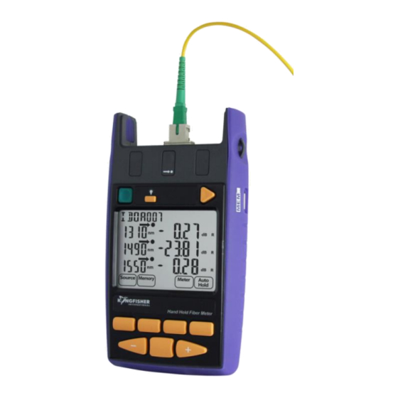
1 General Features Autotest function • Long battery life (up to 1000 hours) • Calibrated at multiple wavelengths (up to 28 ) • Memory – Internal or USB • Industry standard connector adaptors: • Data saved with time-date stamp • interchangeable or screw-on types Text ID: Text naming for test data •... - Page 5 2 KI2600 Series Power Meter Overview & Keypad Layout Connector Cover Remove Connector Lanyard holder Backlight On/Off Store to USB stick USB port for external power USB port for memory stick & computer interface Memory, Text ID, Date [F1 ]~[F4]...
-
Page 6: Operation
3. Operation Select/determine test cord configuration Install/uninstall Optical Connector Adaptor Install/uninstall Batteries Enable/disable Battery Charging Switching On/Off Instrument Go back to... - Page 7 3.1 Select test cord configuration Identify fibre type required for test cord and configuration required. Instrument supplied with SC connector adaptor as standard. SC/SC-hybrid connector adaptor Standard type: XL type: Note : Unlike light sources, power meters accept both PC and APC connectors. Go back to...
- Page 8 3.2 Install / uninstall Connector Adaptor Lightly press and hold Release Button ❶ Adaptor slot with one hand. ❷ ❸ face out Pull out existing adaptor with the other ❷ hand. Push in a new adaptor. ❸ ❶ Go back to...
- Page 9 3.3 Install / uninstall Batteries Caution: Battery charging on instrument must first be disabled when using non-rechargeable batteries. See next page for instructions to disable battery charging. Unclip Battery Compartment Cover at rear of instrument. ❶ Insert/remove batteries (take note of the battery +Ve terminal spring orientation of different instrument models, see images below). ❷...
- Page 10 3.4 Enable / Disable Battery Charging enable rechargeable batteries to be internally charged, this feature must be enabled by means of the supplied 0.1” pitch shorting-pin Instrument supplied in this configuration i.e. battery charging is Disabled: Supplied 0.1” pitch shorting-pin Insert supplied shorting-pin as shown to Enable battery recharging: Supplied 0.1”...
- Page 11 3.5 Switch On/Off Instrument Date To switch on: press the green, [On/Off ] button. Indicates that Auto-power-off To switch off: mode is disabled press the green, [On/Off ] button again. Battery charge indicator Note: the instrument will switch off automatically 10 minutes after it was Per m switched on.
-
Page 12: Instrument Menu Structure
4. Instrument Menu Structure Memory Top level Menu Meter Meter 2’nd level Menu Home Memory Mode Home Hold Set Ref Mode Return to In dBR Select unit: Return to Select unit: Hold Read top level mode, dBm, dBR, Function top level dBm, dBR, display memory... -
Page 13: Modes Of Operation
5. Modes Of Operation Autotest: Automatically toggles between all wavelengths. • Preferred mode for loss testing as testing time is greatly reduced. • Minimises error as meter always displays correct wavelength. • Manual: Single wavelength operation. • Preferred mode for level monitoring. •... - Page 14 5.1 Autotest Operation Mode: • Simplest mode for loss testing. • When receiving light from a compliant source operating in Autotest mode, the meter will auto toggle between wavelengths. Power meter receives data which contains wavelength, source serial number and nominal source output power. ...
-
Page 15: Manual Operation Mode
5.2 Manual Operation Mode: 5.2.1 Switch to Meter function At top level menu, press [F3]. Per m Pe r m d B m M e m o r y M et e r Met er Aut o Hom e Set Ref Mode Hold Go back to... - Page 16 5.2 Manual Operation Mode: • 5.2.2 Select wavelength Toggle [-] or [+] to select he desire wavelength. Note: Wavelength toggle is not circular. • Most meters have the common wavelengths • Pe r m grouped together for speed of access when used in manual mode.
- Page 17 5.3 Test Tone Detection Operation Mode: When instrument is operating in Meter mode, and test tone or low level modulation is detected: Power meter displays modulated frequency and beeps. • To measure power in the presence of tone, SlowMode is used. •...
- Page 18 5.4 Slow Operation Mode: Used when it is necessary to measure power in the presence of test tone or low level modulation e.g. low data rate *SCADA (Supervisory Control And Data Acquisition) transmissions. When this mode is active, the meter’s sample interval is increased. •...
- Page 19 Standards based & user definable analysis • Data Logging • Equipment memory extract to KITS™ or CSV file • Familiar Excel™ User Interface • Inbuilt multi language support • Customisable reports • Kingfisher website for KITS™ user manual Go back to...
-
Page 20: Measurement Display Mode
6. Measurement Display Mode: There are 3 modes for measurement unit display i.e. Absolute dBm / Relative dBR mode / Linear (W) mode. Absolute Mode: • Measure actual power level at a particular location in decibels (dBm). Relative Mode: • Measure power level ‘relative’... -
Page 21: Selecting Display Mode
6.1 Selecting Display Mode: In Meter mode, press repeatedly toggles through Absolute(dBm), Relative(dBR) and Linear(W) modes. [F3] d Bm Pe r m dB R d B m Aut o Met er Hom e Set Ref Mode Hold Go back to... - Page 22 6.2 Setting Reference (in dBR mode): In dBR display mode: Press and hold for approx. 2 seconds. [F2] • Meter will beep 4 times and the display values become “zero”. • Aut o Aut o Perm Perm Aut o Met er Hom e Se t Re f Mod e...
- Page 23 6.2 Setting Reference (in dBR mode) - continue Example of loss measurement in dBR (Reference mode): -6.99 dBm -47.71 dBm (2x 10 (1.67x10 Cabling under test Source Meter 0 dBR -40.72 dBR Loss = Send – Receive dB => Loss = (-6.99) – (-47.71) = 40.72 dB Go back to...
-
Page 24: Memory Operations
Memory Operations Internal Memory Clear Internal Memory Store Internal Memory Recall Dump to USB Memory Go back to... - Page 25 7.1 Internal Memory Clear To enter Memory mode: At top level menu, press [F2]. To clear memory (all): Per m m em Aut o m em Per m • Press and hold [Toggle Centre] then press Mem ory [On/Off] Hom e Mod e Mem ory Hom e...
- Page 26 7.2 Internal Memory Store In Meter or Autotest mode: Note: Press []. Data will be stored in the current memory location • displayed & instrument will beep once. The displayed memory location will increment. • To save data to a specific memory location: Memory location indicator...
- Page 27 7.3 Internal Memory Recall Enter Memory mode: To display content stored in a specific memory locations: At top level menu, press [F2]. Press or [+]. Note: Content of last stored memory location will be displayed. Memory location indicator To toggle between unit displays of dBm, dBR and W: Aut o Aut o Aut o...
- Page 28 7.4 Dump To USB Memory Instrument must be in Memory Mode to detect inserted USB memory stick Enter Memory mode: Sample data dumped from instrument to USB: ❶ Memory Image from KI2X00 SN: 202 Time in 24h format. Wavelengths in nm. Optical Power values in dBm. At top level menu, press [F2].
-
Page 29: Other Features
Other features Instrument Date/time Setting Min-Max Values Display Text ID Go back to... - Page 30 8.1 Instrument Date / Time Setting ❶ Enter Date/time setting mode: To modify the selected ❶ time/date: When instrument is OFF, press and hold [On/Off] & [Toggle Centre] Press [+]. Mem ory Hom e Mod e at the same time. Release the keypads as soon as the date/time setting display comes on.
- Page 31 8.2 Min-Max Value Display Maximum & Minimum power readings are continuously recorded & displayed. (This function is disabled during Autotest). To display Min-Max values: Au t o Per m Per m Press simultaneously. m a x m in Met er Met er Hom e Se t Re f...
- Page 32 8.3 Text ID This feature is used in conjunction with instrument memory-save to identify a location or a cable. Max 20 individual text ID tags can be created in instrument. • Format is 4 letters, followed by 3 digits. • The last 3 digits auto increment.
- Page 33 8.3.1 Creating A New Text ID Tag At top level menu, press [F3]: Press [Toggle centre]: ❶ ❷ Press [Toggle centre]: ❹ To enter Meter mode. The existing ID tag in used will To select the position of the ID be displayed.
- Page 34 8.3.2 Selecting/using The Created Text ID Tag Press Press [F2]: ❸ ❹ At top level menu, ❶ To save the newly selected To display/select the desired ID tag from those created earlier (if available) press [F3] to enter ID tag for use & Exit. Meter mode.
- Page 35 8.3.3 Deleting The Created Text ID Tag Press [F3]: At top level menu, press ❹ Press [F2]: ❻ ❶ To confirm the selection of ID tag [F3] to enter Meter To confirm deletion. Note: The 1’st alphabet of the selected ID tag will be blinking. mode.
-
Page 36: Instrument Firmware
9. Instrument Firmware The KI2000 series Firmware can be end-user upgraded. To update Firmware: Instrument Firmware must be r0.12 or higher. • KI2000 USB device driver software must be installed. • Checking Firmware Version Firmware Upgrading Procedure Go back to... -
Page 37: Checking Firmware Version
9.1 Checking Firmware Version The instrument Firmware version can be checked during instrument switch-on. When instrument if off, hold down [F4] [On/Off The instrument will switch on, and serial number and firmware version is displayed whilst [F4] is held. Serial Number Meter Firmware... -
Page 38: Firmware Upgrade Procedure
9.2 Firmware Upgrade Procedure Download and extract the Firmware Update program from Kingfisher web site. ❶ Connect instrument to computer. ❷ Run Firmware Update program (KI2000 programmer vx.xx.exe) downloadable free from Kingfisher website. ❸ Follow procedures as detailed in the Firmware Update instruction in PDF (KI2000 Programming Instructions ❹... -
Page 39: Instrument Care
10 Instrument Care Keep the instrument in a carry case during storage and transport • Use only high quality batteries. • For prolonged storage remove batteries. • The instrument is resistant to normal dust and moisture, however it is not waterproof. •... -
Page 40: Application Notes
Application Notes Comprehensive selection available at https://www.kingfisherfiber.com/Application-Notes.aspx Go back to... -
Page 41: Questions And Comments
Questions and Comments Go back to... - Page 42 Thank you for your attention Prepared by: TO Ng Date prepared:22 Dec 2016 @kingfisherfiber kingfisherfiber.com Go back to...
Need help?
Do you have a question about the KI2600 Series and is the answer not in the manual?
Questions and answers