Kingfisher KI 2600 Series Operation And Maintenance Manual
Hand held fiber meter; hand held fiber source; hand held loss test meter
Hide thumbs
Also See for KI 2600 Series:
- Training manual (43 pages) ,
- Quick reference manual (19 pages) ,
- Service manual (15 pages)

Related Manuals for Kingfisher KI 2600 Series


Summary of Contents for Kingfisher KI 2600 Series
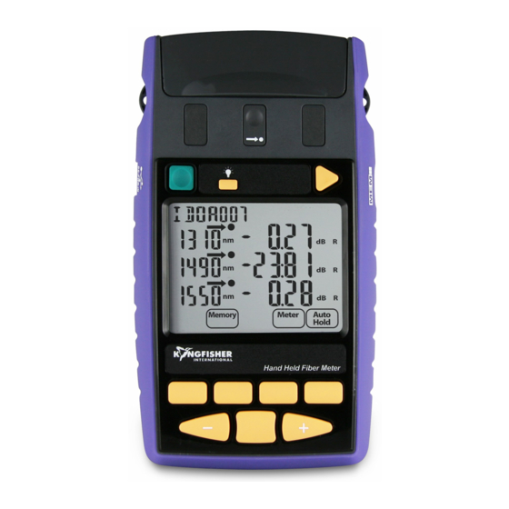
- Page 1 KI 2600 Series Hand Held Fiber Meter KI 2400/KI 2800 Series Hand Held Fiber Source KI 2300/KI 2700 Series Hand Held Loss Test Meter OPERATION AND MAINTENANCE GUIDE...
-
Page 2: Declaration Of Conformity
IEC 60825-2:2011 Safety of laser products - Safety of optical fibre communication systems (OFCS) CFR 21 part 1040.10 (USA) Performance standards for light- emitting products-Laser products Supplemental Information: The product was tested in a typical configuration with Kingfisher International test systems. 10 September 2014 Bruce Robertson... - Page 3 To get the best use from your instrument and to ensure its safe operation, please spend a few minutes to read this manual. Made in Australia. International Patents Granted © Copyright Kingfisher International Pty Ltd Edition, November 2014 KI2000 UM-6...
-
Page 4: Table Of Contents
CONTENTS Recording, Storing, Recalling Readings and Clearing Memory Service and Support PC Interface And External Software Introduction and Applications Care Of Your Instrument General Safety Summary Accuracy Considerations Battery and External Power Definition of Terms Push On Optical Connector Specifications Screw On Optical Connector Ordering Information Getting Started And Turning On... - Page 5 Flip-over connector cover & tilt bail Backlight On/Off Connector Release & Port Identifier Lugs for Carry Strap Store Micro USB port for data and power USB port for memory stick Memory Text ID Battery compartment [F1] [F4] Toggle centre KI2600 SERIES OPTICAL POWER METER KI2000 UM-6...
- Page 6 KI2400/2800 HAND HELD FIBER SOURCE KI2000 UM-6...
- Page 7 KI2300/2700 HAND HELD LOSS TEST METER KI2000 UM-6...
-
Page 8: Service And Support
Qualified personnel must perform adjustment, maintenance or repair Application Notes written to support instrument users, an updated of this product. To obtain service, please contact your local Kingfisher version of this manual or instrument firmware updates. FAQs can be International distributor or our office in Australia: found in the “Support”... -
Page 9: Introduction And Applications
Autotest communicates test data between instruments to automate Test results can be stored in the large memory along with text-input loss testing, and is generally compatible with other series of Kingfisher cable name and timestamp, and then dumped onto a USB memory Autotest instruments. - Page 10 INTRODUCTION AND APPLICATIONS languages and reporting requirements. Real time display and data When performing loss testing using an Autotest light source, up to logging is included. KITS™ enables merging of test results from three wavelengths are displayed simultaneously. More wavelengths multiple instruments and supports bi-directional testing for one way are shown with a scrolling display.
- Page 11 INTRODUCTION AND APPLICATIONS Laser sources at 1310 / 1490 / 1550 / 1625 nm are used for testing single mode fiber systems, and LED sources at 850 / 1300 nm are used for testing multimode fiber systems. The innovative VisiTest option is helpful for general loss testing, continuity testing and fault finding.
-
Page 12: General Safety Summary
Kingfisher International assumes no liability for the apparatus against damage. customer’s failure to comply with these requirements. - Page 13 Operating Environment WARNING! Observe optical safety when using high power. The range of Kingfisher equipment covered by this manual can be Optical safety requirements at high power levels MUST be observed operated at temperatures between -15 °C and +55 °C and at relative or eye damage is likely.
- Page 14 GENERAL SAFETY SUMMARY Laser and LED Safety Information Wavelength Maximum permissible CW output power² Visual laser 650 ±5 nm Surface emitting LED 850nm/1300±20 nm IEC 60825-2 (2011) - International Fabry - Perot laser 1310 / 1550 / 1625 ±20 nm 650 nm, class 2M 10 mW Ultra stable LED...
-
Page 15: Battery And External Power
BATTERY AND EXTERNAL POWER These instruments are powered by two ‘AA’ size batteries, either non If the batteries are changed quickly, instrument date and time are rechargeable 1.5V alkaline or lithium; or rechargeable NiMh with retained, however if the batteries are taken out for longer or are jumper selected charging. - Page 16 Protect our environment! Some batteries contain toxic heavy metals, so please dispose of them by returning to a re-cycling centre. Batteries purchased from Kingfisher agents can be returned to them for appropriate disposal. Figure 1A. To enable charging, programming jumper links two left pins Figure 1B.
-
Page 17: Push On Optical Connector
PUSH ON OPTICAL CONNECTOR This section applies to instruments with push-on pull-off interchangeable Power Meter: optical adaptors. This port can be used with both PC and APC connector styles. To access the optical connector, grasp the grey cover on the top of the Bare fiber adaptors must achieve fiber eccentricity of ±... - Page 18 PUSH ON OPTICAL CONNECTOR How to clean the optical connectors So, if your instrument has had considerable use, the removable connector adaptor may be worn out and need replacing. Always clean the mating connector tip and ferrule before mating, using approved materials.
-
Page 19: Screw On Optical Connector
SCREW ON OPTICAL CONNECTOR This section applies to power meters with large area detectors and CAUTION! Never use abrasive cleaners or permanent detector screw-on interchangeable optical adaptors. damage may occur. To access the optical connector, grasp the grey cover on the top of This port can be used with both PC and APC connector styles the instrument and tilt it back. -
Page 20: Getting Started And Turning On
GETTING STARTED AND TURNING ON This section shows basic instrument operation. Or to turn on the Power Meter for permanent operation, press the [On/Off] for 3 seconds until ‘on’ and ‘Perm’ is displayed To add a carry strap, slip the end of a strap through the eyes on the on the sides of the instrument, and secure the buckle. - Page 21 GETTING STARTED AND TURNING ON To disable or activate beeping, hold [F2]. To view firmware version, hold [F4]. To enter SlowMode, hold down [F3]. To disable or activate beeping, hold [F2]. Light Source Loss Test Meter To turn on the Light Source, press [On/Off] (square green button in the To turn on the Loss Test Meter, press [On/Off] (square green button top row).
- Page 22 GETTING STARTED AND TURNING ON To backlight the display, press [Backlight], (top row). To turn the instrument off, press [On/Off] again. Also at turn-on: To disable auto-off timer, hold [On] for 3 sec. To set time & date, hold down [Toggle centre]. ...
-
Page 23: Setting Date And Time
SETTING DATE AND TIME Test date and time are stored with test results. So if the instrument memory or KITS software are used to record results, the user will probably want to set the date and time. If the instrument loses power for some time, date and time will be lost and will need to be re-entered. -
Page 24: Autotest
To view reference value, press [Meter Mode] to enter dB R, then Any Kingfisher Autotest source / power meter / loss test set / two-way tester press [+]. can be used as a source & meter, for one direction loss testing. Both ... -
Page 25: Patch-Lead Test Using Loss Test Meter
PATCH-LEAD TEST USING LOSS TEST METER This section illustrates the instruction to use Loss Test Meter to Thru-connector perform simple IL (Insertion Loss) measurement on a patch-lead. Reference patch-lead adapter Connect a reference patch-lead (test grade) between the light Patch-lead to be tested source and power meter ports of Loss Test Meter as shown below;... -
Page 26: Manual Operation-Power Meter
MANUAL OPERATION-POWER METER This section summarises manual operation of the KI2600 Series To display, hide or reset minimum and maximum recorded Power Meter, most used when performing absolute power power for selected wavelength, press [-] and [+] measurements on transmission equipment, or if Autotest is not simultaneously. -
Page 27: Manual Operation-Light Source
MANUAL OPERATION-LIGHT SOURCE This section summarises manual and advanced Autotest operation of To start limited wavelength AutoTest, press and hold [Toggle the Light Source. For general Autotest, refer to the Autotest section. centre], then press [Auto]. Press [Source]. ... -
Page 28: Visible Laser Operation
VISIBLE LASER OPERATION This is applicable to KI2800 and KI2601 Series instruments. VisiTester is activated automatically when the relevant source port is equipped with VFL: a visible light sequence is included in the test A visible laser is a useful low skill fault finding tool and is either PC or sequence. -
Page 29: Tone Detection And Slow Mode
TONE DETECTION AND SLOW MODE Tone detection To enter SlowMode, during turn on, hold down [F3] (button located in the middle row right from the centre). ‘-tonE’ will This is a very useful feature for quick continuity / polarity checking. It be displayed briefly. -
Page 30: Text Id Tag
TEXT ID Tag Text ID tag is useful pre-set feature to systematically add text names Press [F3], the character to be edited will flash. to test results in memory. Press [-] or [+] to select new alphanumeric character, then press [Toggle centre] to move to the next. - Page 31 TEXT ID Tag Note: Text ID tag detail is independent of the actual memory location within the instrument. An identical Text ID tag number can be re-used, and it will store in the next available empty memory location. Text ID tags can only be deleted one at a time. KI2000 UM-6 29 -...
-
Page 32: Recording, Storing, Recalling Readings And Clearing Memory
RECORDING, STORING, RECALLING READINGS AND CLEARING MEMORY KI2600 Series instruments provide various options for storing and User Memory recording data. The non-volatile user memory stores test data, which can then be Meter Reference Value displayed or downloaded to the spreadsheet in the KITS™ software or saved to a USB stick. - Page 33 RECORDING, STORING, RECALLING READINGS AND CLEARING MEMORY Recording data to memory To access memory locations and to select stored readings, enter Memory menu and press [+] or [-]. Make sure that the required Text ID Tag is showing. If not, refer to ...
- Page 34 RECORDING, STORING, RECALLING READINGS AND CLEARING MEMORY Memory capacity Memory capacity is 999 sets of 1 - 4 wavelength measurements. KI2000 UM-6 32 -...
-
Page 35: Pc Interface And External Software
PC INTERFACE AND EXTERNAL SOFTWARE The KI2600 Series instruments feature a micro USB interface which gives remote access and control from an external PC. Note that the larger USB port marked “MEM” is only used to dump data onto a USB memory key, and has no other function. When the instrument is connected to a PC or power supply via a micro USB cable, the battery symbol “... -
Page 36: Care Of Your Instrument
CARE OF YOUR INSTRUMENT Clean the instrument case using soft damp cloth. Do not use Follow the directions in this manual on optical connector care. strong solvents to avoid risk of damage to surfaces. During prolonged storage, remove batteries to eliminate the ... -
Page 37: Accuracy Considerations
LED source may be preferred. High power (attenuated) meters tend to suffer overall reduced accuracy. Kingfisher high power meters have better general accuracy than most others, since our meters use a more sophisticated KI2000 UM-6... - Page 38 ACCURACY CONSIDERATIONS DWDM Loss and Power Measurements CWDM Loss and Power Measurements The DWDM bands are typically within 1525 ~ 1610 nm. For this The CWDM band is from 1270 ~ 1610 nm at 20 nm spacing, however, application, an InGaAs detector calibrated at 1550 nm gives good 1490 ~ 1610 nm is more common since it avoids the water absorption absolute accuracy at all DWDM wavelengths.
- Page 39 ACCURACY CONSIDERATIONS KI2000 UM-6 37 -...
-
Page 40: Definition Of Terms
DEFINITION OF TERMS Power Meter meter, a 9/125µm fiber, at constant temperature, within a specified temperature window, and at line voltage. Power Range: The range of input powers for which the instrument can be used. Center wavelength: The wavelength representing the centre of mass of the selected peaks: Maximum Input Power: The input power not to be exceeded to avoid destroying the instrument. -
Page 41: Specifications
SPECIFICATIONS Size: 190 x 105 x 35 mm (7.5 x 4.1 x 1.4”) Case: Rubber/Polycarbonate, 1 metre drop tested. Weight: 420 gm (0.9 lb). Shipping 1.5 Kg (3.3 lb). Display: High contrast custom LCD, Operating/ Storage: -15 to 55 °C / -25 to 70 °C. 74 x 55 mm / 2.9 x 2.2”... - Page 42 SPECIFICATIONS Power Meter: - KI2600 Series Damage Power Autotest Mid range Calibration Polarisation Total Detector Response Calibration Level Range Sensitivity Linearity¹ Accuracy Sensitivity Uncertainty Type 780, 820, 850, 980 +10 ~ -60 1270, 1290, 1300, 1310, 1330, +10 ~ -70 1350, 1370, 1390, 1410, 1430, InGaAs 600 ~ 1700...
- Page 43 SPECIFICATIONS Power Meter: - KI2600XL Series Response uniformity Response Damage Power Autotest Mid range Calibration Polarisation Total Calibration Sensitivity Detector across Level Range Sensitivity Linearity¹ Accuracy Sensitivity Uncertainty Type ±30nm detector KI2600H3BXL-InGaAs2 +33 ~ -30 Filtered 2 +33 ~ -40 980,1270,1300,1310,1330,1350, 800 ~ 1700...
- Page 44 SPECIFICATIONS Power Meter: - KI2300/KI2700 Series Damage Power Autotest Mid range Calibration Polarisation Total Detector Response Calibration Sensitivity Level Range Sensitivity Linearity¹ Accuracy Sensitivity Uncertainty Type ±30 nm dB 780, 820, 850, 980, +10 ~ -60 1270, 1290, 1300, 1310, 1330, 1350, +10 ~ -70 InGaAs 600 ~ 1700...
- Page 45 SPECIFICATIONS Optical Light Source: KI 2800 Series 1310/1550 nm Other Laser 650 nm 850 / 1300 nm 1310 /1550 nm Comments Laser VisiTest -20 @ 62.5/125 1 ~ 2 : -4 @ 9/125 Output Power, dBm/ 0 @ 9/125 -22 @ 50/125 ...
- Page 46 SPECIFICATIONS Optical Light Source: KI 2400 Series 1310/1550 nm Other Laser 850 / 1300 nm 1310 /1550 nm Comments Laser -20 @ 62.5/125 1 ~ 2 : -4 @ 9/125 Output Power, dBm/ -4 @ 9/125 -22 @ 50/125 -20 @ 9/125 ...
- Page 47 SPECIFICATIONS Optical Light Source: KI2700 Series 1310/1550 nm Other Laser 650 nm 850 / 1300 nm Comments Laser VisiTest -20 @ 62.5/125 1 ~ 2 : -3 @ 9/125 Output Power, dBm/ 0 @ 9/125 -22 @ 50/125 1 dB Fiber Type, m 3 ~ 4 : -7 @ 9/125 -32 @ 9/125...
- Page 48 SPECIFICATIONS Optical Light Source: KI 2300 Series 1310/1550 nm Other Laser 850 / 1300 nm Comments Laser -20 @ 62.5/125 1 ~ 2 : -4 @ 9/125 Output Power, dBm/ -4 @ 9/125 -22 @ 50/125 1 dB Fiber Type, m 3 ~ 4 : -7 @ 9/125 -32 @ 9/125 For 15 min, typ ...
-
Page 49: Ordering Information
ORDERING INFORMATION Power Meter: KI2600 Series Instrument, Power Meter InGaAs KI2600 - InGaAs Instrument, Power Meter InGaAs, VFL KI2601 - InGaAs Instrument, Power Meter Ge KI2600-Ge Instrument, Power Meter Ge, VFL KI2601-Ge Instrument, Power Meter H5 KI2600 - H5 Instrument, Power Meter H5, VFL KI2601 - H5 Power Meter: KI2600XL Series Instrument, Power Meter Ge 5mm... - Page 50 ORDERING INFORMATION Light Source: KI2400 Series Instrument, Source 1310-1550 nm ultra stable Laser KI2422 Instrument, Source 1310-1550-1625 nm ultra stable Laser, APC KI24010-APC Instrument, Source 1310-1550 nm ultra stable eLED KI2419 Loss Test Meter: KI2700 Series Instrument, LTS 1310-1550 nm, InGaAs KI 2722-InGaAs Instrument, LTS 1310-1550 nm VisiTester, InGaAs KI 27622-InGaAs...
- Page 51 ORDERING INFORMATION Standard Accessories: Optional Accessories: SC metal-free optical connector adaptors, KITS™ PC software and USB Description cable, user manual, calibration certificates, carry pouch, carry strap. Option, Carry Case for 2 Instruments OPT153 Optical Connectors: Option, Carry Case includes Cletop-style cleaner & Cleaning Sticks OPT154B These instruments have interchangeable optical connectors.
- Page 52 ORDERING INFORMATION Standard Accessories (for KI2600XL series): Optional Interchangeable Connector Adaptors (for KI2600XL series): Quantity Description Description Description Operating manual OPT202 Universal 1.25mm OPT224 Calibration certificate OPT201 Universal 2.5mm OPT225 KITS™ Recording/Reporting software E2000/LSH OPT220 LSA/DIN OPT207 Soft carry pouch OPT221 Wrist strap OPT206...
-
Page 53: Calibration And Maintenance
CALIBRATION AND MAINTENANCE There are no internal user adjustments. Calibration is performed Known calibration constants can be re-entered directly without using without opening the instrument. other equipment. This is useful in case old calibration constants are to be put back. Before commencing calibration: Record the existing calibration offsets, re-enter or adjust known ... - Page 54 CALIBRATION AND MAINTENANCE To save new calibration setting, press [Set Ref]. To return to main calibration menu, press [Home] To cancel unsaved changes, press [Toggle centre] or To cancel unsaved changes, press [Home]. [Home]. Light Source Calibration ...
-
Page 55: Performance Verification Tests
PERFORMANCE VERIFICATION TESTS All tests can be performed without access to the interior of the Instrument Specification Specifications are the performance instrument. characteristics of the instrument that are certified, and are the limits against which the equipment under test can be tested. The test procedures described in this section are for performance verification of a KI2600 InGaAs Power Meter and KI2822 Light Source. - Page 56 PERFORMANCE VERIFICATION TESTS Power Meter: Change the attenuation of the attenuator until the reference power meter displays -10.00 dBm. Note the attenuator setting Accuracy Test in setting 1 of Table 4. Connect the Power Meter to Attenuator to Light Source: If the light source is powerful enough to give -4.00 dBm, set the attenuator to 2.5 dB and correct the appropriate values in the test report.
- Page 57 PERFORMANCE VERIFICATION TESTS Verification of Autotest range, tone detector and linearity test For multimode instruments, repeat the power readings for attenuator settings of 15 dB, 20 dB. Test below is to verify Autotest range, tone detector operation and linearity for Power Meter. Connect the Power Meter to Attenuator to Repeat the above for 1550nm as required, however, this test Light Source typically only needs performing at one wavelength.
- Page 58 PERFORMANCE VERIFICATION TESTS Optical Light Source Output Power (CW) Test Connect the Light Source to the Power Meter as shown. Switch on the instruments. Set the Optical Power Meter to 1310 nm On Light Source, enable the source and set the wavelength to 1310 nm.
- Page 59 PERFORMANCE VERIFICATION TESTS Short Term Stability Test (optional) Time Measured power, Drift, dB Tick max/min Connect the Light Source to the Power Meter as shown. For values better stability, ensure that connector plugged into power meter has APC termination. 00 sec 0.00 Set the optical power meter to 1310 nm.
- Page 60 PERFORMANCE VERIFICATION TESTS Optical Light Source From the displayed measurements check and note the values for "mean wavelength" (Centre wavelength) and "FWHM" Centre wavelength and Spectral Bandwidth (FWHM) Test (optional) (Spectral Bandwidth) in the test report, Table 6. Connect the Light Source to OSA as shown. Repeat the test with the source wavelength set to 1550 nm.
- Page 61 PERFORMANCE VERIFICATION TESTS Instrument / Accessories Recommended Model Required Characteristics Alternative Model Optical Light Source KI2400 KI7400C, KI7800C Optical Power Meter KI2600 KI7700C Optical Attenuator KI7013B KI7013B Connector adaptors SMF patch leads For optional test only Optical Spectrum Analyser 71450B 71452B, (8164xA,B) Connector Adaptors SMF patchleads...
- Page 62 PERFORMANCE VERIFICATION TESTS Model: Date: Serial No.: Ambient Temperature: C Options: Relative Humidity: Firmware Revision: Line Frequency: Test Facility: Customer: Performed by: Report No.: Special Notes: KI2000 UM-6 60 -...
- Page 63 PERFORMANCE VERIFICATION TESTS Table 2: General Test Record KI2000 UM-6 61 -...
- Page 64 PERFORMANCE VERIFICATION TESTS Description Model No. Trace No. Calibration due date Optical Light Source Optical Power Meter Optical Attenuator Accessories: SMF patchleads Connector adaptors Table 3: Equipment Record for Performance Verification Tests KI2000 UM-6 62 -...
- Page 65 PERFORMANCE VERIFICATION TESTS Model: Report No.: Date: Total Uncertainty / Accuracy Test Test Wavelength = Setting Power Meter Attenuator Minimum specification Maximum specification Number reference value Setting (-0.3 dB of Ref.) measurement results (+0.3 dB of Ref.) (~-10.00 dBm) (~-10.30 dBm) (~-9.70 dBm) (~-20.00 dBm) (~-20.30 dBm)
- Page 66 PERFORMANCE VERIFICATION TESTS PERFORMANCE VERIFICATION TESTS Model: Report No. Date: Output Power (CW) Test Wavelength Minimum Specification Maximum Specification Measurement Results 1310 nm -1.00 dBm 1550 nm -1.00 dBm Measurement Uncertainty Short-Term Stability Test (optional) 1310 nm dBpp (0.10 dBpp) 0.04 dBpp typical 1550 nm dBpp (0.10 dBpp) 0.04 dBpp typical...
- Page 67 PERFORMANCE VERIFICATION TESTS Model: Report No: Date: Central Wavelength & Spectral Bandwidth (FWHM) Test (optional) Wavelength Minimum Spec. Maximum Spec. Measurement Results Centre wavelength 1310 nm 1290 nm 1330 nm 1550 nm 1530 nm 1570 nm Spectral Bandwidth (FWHM) 1310 nm (6nm) 3 nm typical 1550 nm (6nm) 3 nm typical...
- Page 68 PERFORMANCE VERIFICATION TESTS Instrument Connector: Model: APC [ PC [ Report No.: Date: Fiber Type: Single mode [ ] Multimode [ ] Range and Linearity Test Attenuator setting Power Meter Reading Linearity Calculation Acceptable Linearity Range 5.00 dB 15.00 dB No 2 –...
-
Page 69: Quick Reference Guide
QUICK REFERENCE GUIDE: POWER METER KI2600 POWER METER, KI2300/KI2700 LOSS TEST METER To store to memory press [Store] Manual operation Autotest Operation To remove interchangeable connector adaptor, press button To start Autotest, press [AUTOTEST] on Light source. on front of case and pull off adaptor. - Page 70 QUICK REFERENCE GUIDE: LIGHT SOURCE KI2400/KI2800 HAND HELD FIBER SOURCE, To end modulation, press and hold [Mode] then press KI2300/KI2700 LOSS TEST METER [Toggle centre]. Alternatively, press and hold [Mode] for 3 sec. Manual operation Autotest Operation To remove interchangeable connector adaptor, press button on front of case and pull off adaptor.
-
Page 71: Disclaimer And Warranty
Information in this manual is given in good faith for the benefit of the KINGFISHER INTERNATIONAL PTY. LTD. user. It cannot be used as the basis for claims against Kingfisher 30 Rocco Drive, Scoresby, VIC 3179 Australia International or its representatives, if accidental damage or inconvenience results from use or attempted repair of the equipment. - Page 72 NOTES Please use these pages to write notes KI2000 UM-6 70 -...
- Page 73 NOTES KI2000 UM-6 71 -...
- Page 74 NOTES KI2000 UM-6 72 -...
Need help?
Do you have a question about the KI 2600 Series and is the answer not in the manual?
Questions and answers