
Related Manuals for Kingfisher KI9600A


Summary of Contents for Kingfisher KI9600A
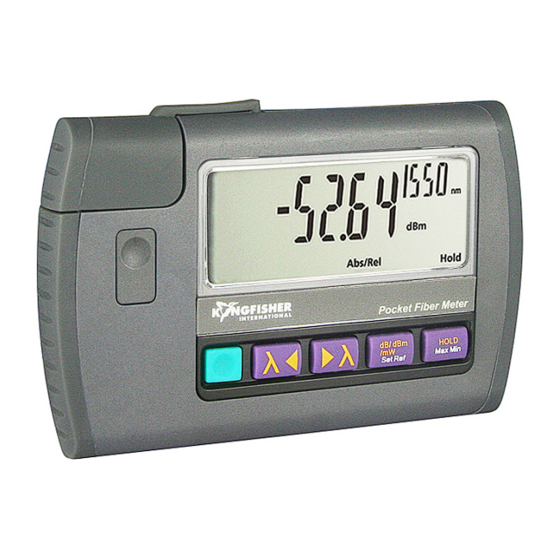
- Page 1 KI 9600 Series Power Meter KI 9800 Series Light Source OPERATION & MAINTENANCE GUIDE...
- Page 2 The product was tested in a typical configuration with Kingfisher International test systems. 28 Apr 2021 Bruce Robertson Date Name Technical Director Title For further information, please contact your local Kingfisher International sales office, agent or distributor. Revision: G Issue Date: 28 Apr 2021...
- Page 3 To get the best use from your equipment and ensure its safe operation, please spend a few minutes to read this manual. Worldwide recognized accuracy and quality ISO 17025 Made in Australia. International Patents Granted © Copyright Kingfisher International Pty Ltd Edition, Apr 2021 KI 9000 UM-14...
-
Page 4: Table Of Contents
CONTENTS Service, Calibration and Support Accuracy Considerations Introduction and Applications Definition of Terms General Safety Summary Specifications Battery Power Ordering Information Optical Connector Calibration and Maintenance Operation Performance Verification Tests TamperLock Mode Quick Reference Guide Autotest Mode Disclaimer and Warranty Care of your Instrument User Notes KI 9000 UM-14... - Page 5 KI9600A Series Optical Power Meter and KI9800 Series Optical Light Source KI 9000 UM-14...
-
Page 6: Service, Calibration And Support
SERVICE, CALIBRATION AND SUPPORT Applications Support Qualified personnel must perform adjustment, maintenance or repair of this product. To obtain service, please contact your local Kingfisher Please visit www.kingfisherfiber.com to see our comprehensive International distributor or our office in Australia Application Notes written to support instrument users. -
Page 7: Introduction And Applications
INTRODUCTION AND APPLICATIONS The KI 9000A Series Optical Power Meter and Optical Light Source Detector options include Germanium (Ge), Indium Gallium Arsenide offer both ease of use and superb measurement confidence. They are (InGaAs), Silicon (Si), high power, large area and wavelength very convenient to use and, have reduced cost of ownership. - Page 8 INTRODUCTION AND APPLICATIONS Light Source features Multiple wavelength sources have 1 - 3 switchable wavelengths Light sources have re-connection repeatability of 0.1dB. Combined through one port, which makes operation faster. with the instrument excellent stability, this provides more accurate measurement results and improved test confidence. Laser sources at 1490 / 1310 / 1550 / 1625 nm are used for testing single mode fiber systems.
-
Page 9: General Safety Summary
Failure to comply with these precautions or with specific warnings elsewhere in this manual violates safety standards of design, manufacture and intended use of the instrument. Kingfisher International assumes no liability for the customer’s failure to comply The apparatus will be marked with this symbol when it is necessary for with these requirements. - Page 10 WARNING! Observe optical safety when using high power. Optical safety requirements at high power levels MUST be observed The range of Kingfisher equipment covered by this manual can be operated at temperatures between -15 °C and +55 °C and at relative or eye damage is likely.
- Page 11 GENERAL SAFETY SUMMARY Kingfisher Laser Eye Safety Information Labelling for this product defers to IEC 60825 as per CDRH Laser Notices No. 50 (2007) & 56 (2019). Annual FDA reports are lodged This information on laser eye safety compliance covers all standard by Kingfisher.
-
Page 12: Battery Power
1.8 V. The instrument may be damaged. When the batteries are low, the low battery indicator is shown on the Protect our environment! Batteries purchased from Kingfisher agents display. At this stage, there is approximately enough energy for can be returned to them for appropriate disposal. -
Page 13: Optical Connector
OPTICAL CONNECTOR Light Source and Standard Power Meter Bare fiber adaptors must achieve fiber eccentricity of ± 100 microns, and end tolerance of ± 300 microns relative to the ferrule end. To access the optical connector, grasp the top left corner of the Preferred bare fiber adaptors consist of a connector with fiber retention instrument, and pull off the cover. - Page 14 OPTICAL CONNECTOR CAUTION! The use of bare fiber adaptors is not recommended as Large Area Power Meter permanent instrument damage will occur. The window on the large area detector is delicate and should not be How to clean the optical connectors scratched, pushed or banged.
-
Page 15: Operation
OPERATION: Power Meter WARNING! Observe optical safety procedures relevant to the power To toggle logarithmic / relative/ linear display modes, press [dB / dBm levels being measured. / mW]. The display will show ‘dB’ or ‘dBm’ or ‘nW’. To switch on KI 9600 instrument for permanent operation, press and To stop / start display update, press [Hold]. - Page 16 OPERATION: Power Meter SlowMode See Quick Reference Guide at the end of this manual for SlowMode Slow mode is used to measure power on unstable signals, or signals operation that accidentally trigger tone detection. In this mode, Autotest and tone detection are disabled, and measurement integration time is extended.
- Page 17 OPERATION: Light Source WARNING! Observe optical safety procedures relevant to the light • Modulation is active only while the source is enabled. To select a source power levels. modulation tone, press [MOD] to scroll through available settings. To switch on KI 9000 instruments for permanent operation, press and •...
-
Page 18: Tamperlock Mode
TAMPERLOCK MODE TAMPERLOCK Light Source TamperLock Mode enables lower skill, repetitive and error-free While in TamperLock Mode, the user is prevented from changing measurements, such as fixed wavelength or laser output power. wavelength or laser output power. This is useful to, for example, pre-set an instrument for use by See Light Source Quick Reference Guide at the end of this manual for unskilled personnel, or to just lock the instrument down for easy use TamperLock operations. -
Page 19: Autotest Mode
Instrument compatibility Any Kingfisher Autotest source / power meter / loss test set / two-way tester can be used as a source & meter, for one direction loss testing. Both instruments must have matching source and meter wavelengths. -
Page 20: Care Of Your Instrument
CARE OF YOUR INSTRUMENT Follow the directions in this manual on optical connector care. • Clean the instrument case using alcohol or other none solvent cleaning agents. Acetone or other active solvents may damage the • Use only high quality sealed alkaline or NiMH or NiCad batteries. case. -
Page 21: Accuracy Considerations
ACCURACY CONSIDERATIONS All Measurements For better accuracy or linearity at wavelengths from 1000 – 1550 nm, or wavelengths above 1550 nm, the InGaAs meter is preferred. Keep optical connectors clean and in good condition. APC connectors will generally provide improved power stability on single mode For high power testing, the H series meters offer excellent accuracy, systems. - Page 22 ACCURACY CONSIDERATIONS Uncertainty due to +/- 30 nm λ tolerance Normalized Power Meter Response 25ºC 0ºC InGaAs 0.10 0.40 0.40 1300 0.06 0.06 0.01 1550 0.50 0.05 1610 2.80 0.03 Ge 0 ºC Ge 25 ºC InGaAs 1000 1100 1200 1300 1400 1500...
-
Page 23: Definition Of Terms
DEFINITION OF TERMS Power Meter power during this time. Measured with an averaging optical power meter, a 9/125 or 62.5 µm fiber, at constant temperature, and within a Power Range: the range of input powers for which the instrument specified temperature window. can be used. -
Page 24: Specifications
SPECIFICATIONS General Specifications: Size: 124 x 81 x 25 mm, 4.9" x 3.2" x 1" Weight: 150 gm, 0.3 lb Power Meter XL Series 160 gm, 0.4 lb Shipping 0.5 Kg, 1.1 lb. Operating/ Storage: -15 to 55 °C / -25 to 70 °C. Power: 2 alkaline ‘AAA’... - Page 25 SPECIFICATIONS KI 9800 Optical Light Source: 1310 or 1310/1490/ 1310/1550/ 1310/1550 1310/1625 1550 nm 1625 nm 635 nm 650 nm 850 nm 850 / 1300 nm 660 nm nm Laser nm Laser Laser Laser Laser Laser VCSEL Comments -20 @ 62.5/125 ±...
- Page 26 SPECIFICATIONS KI 9600 Series Optical Power Meter Detector Response Damage Tone & Power Midrange Calibration Polarization Total Calibration λ λ type level mulit-fiber range linearity Accuracy Sensitivity Uncertainty Sensitivity λ ± 30 nm dB sensitivity 600 ~ < 0.005 0.03 1300, 1310, 1390, 1490, InGaAs +5 ~ -60...
- Page 27 SPECIFICATIONS KI 9600XL Series Large Area Optical Power Meter Detector type Response Damage Power Midrange Calibration Polarisation Total Calibration λ λ level range linearity¹ Accuracy Sensitivity Uncertainty³ Sensitivity λ ± 30 nm 635,650,660,780,1610,1625 +10 ~ -35 5 mm 600 ~ 1650 0.06 <...
-
Page 28: Ordering Information
ORDERING INFORMATION KI 9600 Series Optical Power Meter: Large Area (5mm) Ge Power Meter KI 9600XL – Ge 5 Larger Area (7mm) Ge Power Meter KI 9600XL – Ge 7 Instrument, Power Ge KI 9600A - Ge Large Area Si Power Meter KI 9600XL –... - Page 29 ORDERING INFORMATION specify instrument and at least one optional interchangeable Optional Accessories for KI 9600XL Series: connector adaptor. Option, Carry Case for two KI2xxx / KI3xxx / KI7xxx (OPT153), Option, Carry Case include Cletop & Cleaning Sticks for KI2xxx / KI3xxx / KI7xxx (OPT154B) KI 9000 UM-14...
- Page 30 ORDERING INFORMATION KI 9800 Series Optical Light Source: Standard Accessories: Instrument, Source 635 nm VFL Laser KI9807A SC connector adaptors, QRG, 50µm and 62.5µm mandrel wraps (LED source only), quality assurance certificate, carry strap, soft carry Instrument, Source 650 nm VFL Laser KI9808A pouch.
-
Page 31: Calibration And Maintenance
CALIBRATION AND MAINTENANCE There are no internal user adjustments. Calibration is performed To enable calibration mode, remove belt clip and anti-tamper label at without opening the instrument. the back of the instrument and insert a 2.54 mm (0.1”) pitch programming shunt across pins. Manipulation of the shunt is easier Before commencing calibration: with needle nose pliers. - Page 32 CALIBRATION AND MAINTENANCE Power Meter Calibration Inserting the 2.54 mm (0.1”) pitch programming shunt across • pins will put the instrument into calibration mode. It will Calibration is a transfer process. It is performed by setting up a light display ‘CAL’. source at a stable, but non-critical power level between 0 and -30 dBm, Press [λ] or [λ] to set the wavelength to be calibrated.
- Page 33 CALIBRATION AND MAINTENANCE Light Source Calibration Opening the Instrument: The emitter power level can be re-calibrated, and the current checked. CAUTION! Required are reference power meter with appropriate calibrated Do not open unless warranty has expired and you are • wavelengths, single mode and multimode test leads, an anti-tamper authorised to do so.
-
Page 34: Performance Verification Tests
PERFORMANCE VERIFICATION TESTS The tests procedures described in this section are for performance Any changes in the specifications due to manufacturing changes, verification of a KI9600-InGaAs Optical Power Meter and KI9822 design, or traceability to NATA, will be covered in a manual change supplement, or revised manual. - Page 35 PERFORMANCE VERIFICATION TESTS Required Alternative Instrument / Accessory Recommended Model Characteristics Model Optical Light Source KI9822A KI2400 series, KI2800 series Optical Power Meter KI9600-InGaAs KI2600 series Optical Attenuator KI7013B For optional test only Optical Spectrum Analyzer Agilent 71450B or equivalent Table 1.
- Page 36 PERFORMANCE VERIFICATION TESTS Optical Power Meter 4. Change the attenuation of attenuator until the optical power meter displays -10.00 dBm. Note the attenuator setting in setting 1 of Accuracy Test Table 4. 1. Connect the equipment as shown in Figure 2: If the laser source is not powerful enough to give -10 dBm, set the attenuator to 2.5 dB and correct the appropriate values in the test report.
- Page 37 PERFORMANCE VERIFICATION TESTS Optical Light Source Output Power (CW) Test 1. Connect the equipment as shown in Figure 3. 2. Switch on the instruments. 3. Set the Optical Power Meter to 1310 nm 4. On Light Source, enable the source and set the wavelength to 1310 nm. 5.
- Page 38 PERFORMANCE VERIFICATION TESTS Optical Light Source 4. Let the unit warm-up for 15 minutes then note the power. Short Term Stability Test (optional) 5. Record the power every 30 seconds for 3 minutes. 1. Connect the equipment as shown in Figure 4. For better stability, 6.
- Page 39 PERFORMANCE VERIFICATION TESTS Optical Light Source 4. On the OSA, press the [Instr Preset] key Centre wavelength and Spectral Bandwidth (FWHM) Test (optional) 5. Press [Auto/Meas] and wait until 'End of Automeasure' is displayed 1. Connect the equipment as shown in Figure 5. 6.
- Page 40 PERFORMANCE VERIFICATION TESTS Model: Date: Serial No.: Ambient Temperature: °C Options: Relative Humidity: Firmware Revision: Line Frequency: Test Facility: Customer: Performed by: Report No: Special Notes: Table 2. General Test Record for KI 9600 and KI 9800 KI 9000 UM-14...
- Page 41 PERFORMANCE VERIFICATION TESTS Description Model Trace No. Calibration Due Date Optical Light Source Optical Power Meter Optical Attenuator Accessories Singlemode Fiber Connector Adaptors Table 3. Equipment Record for KI 9600 and KI 9800 Performance Verification Tests. KI 9000 UM-14...
- Page 42 PERFORMANCE VERIFICATION TESTS Model: ________________________ Report No: ______________ Date: ________________ Accuracy Test Test Wavelength = Setting Minimum Specification Maximum Specification Power meter Attenuator Number Measurement results (-0.3 dB of Reference) (+0.3 dB of Reference.) Reference value Setting ~- 10.00 dBm) ~- 10.30 dBm) ~- 9.70 dBm) ~- 20.00 dBm)
- Page 43 PERFORMANCE VERIFICATION TESTS Model: Report No. Date: Output Power (CW) Test Wavelength Minimum Specification Maximum Specification Measurement Results 1310 nm -1.00 dBm 1550 nm -1.00 dBm Measurement Uncertainty Short-Term Stability Test (optional) 1310 nm dBpp (0.10 dBpp) 0.04 dBpp typical 1550 nm dBpp (0.10 dBpp) 0.04 dBpp typical...
- Page 44 PERFORMANCE VERIFICATION TESTS Model: Report No: Date: Central Wavelength & Spectral Bandwidth (FWHM) Test (optional) Wavelength Minimum Spec. Maximum Spec. Measurement Results Centre wavelength 1310 nm 1290 nm 1330 nm 1550 nm 1530 nm 1570 nm Spectral Bandwidth (FWHM) 1310 nm (6nm) 3 nm typical 1550 nm (6nm) 3 nm typical...
-
Page 45: Quick Reference Guide
QUICK REFERENCE GUIDE – KI 9600 Series Optical Power Meter • To remove interchangeable connector adaptor, press • To set reference, press and hold [Set Ref] for more the button on the front of the instrument and pull off than 3 sec. When in reference mode, the reference adaptor. - Page 46 QUICK REFERENCE GUIDE – KI 9600 Series Optical Power Meter then press and hold [HOLD]. To start SlowMode, press and hold [dB/dBm/mW Set • When display show “codE”, enter six key sequence Ref] while turning power meter on. “- tonE” will be (all keys other than [POWER] can be used).
- Page 47 QUICK REFERENCE GUIDE – KI 9800 Series Optical Light Source • To remove interchangeable connector adaptor, press • Modulation is active only while the source emitter is the button on the front of the instrument and pull off enabled. To select a modulation tone, press [MOD] to adaptor.
- Page 48 QUICK REFERENCE GUIDE – KI 9800 Series Optical Light Source • Press and hold [LEVEL], then press [λ] for 3 • To clear TamperLock Mode, turn off instrument then seconds to set output power to factory default. press [POWER] while holding down [λ] and Alternatively, press [POWER].
-
Page 49: Disclaimer And Warranty
Information in this manual is given in good faith for the benefit of the use. Opening the instrument will invalidate the warranty. Liability is user. It cannot be used as the basis for claims against Kingfisher limited solely to repair of the equipment. -
Page 50: User Notes
NOTES KI 9000 UM-14... - Page 51 NOTES KI 9000 UM-14...
- Page 52 NOTES KI 9000 UM-14...
Need help?
Do you have a question about the KI9600A and is the answer not in the manual?
Questions and answers