Table of Contents
Advertisement
Quick Links
Operating instructions
Ozone generation system
DULCOZON type OZLa
EN
A3467
Target group: trained users
Please carefully read these operating instructions before use. · Do not discard.
The operator shall be liable for any damage caused by installation or operating errors.
The latest version of the operating instructions are available on our homepage.
Part no. 990175
Original operating instructions (2006/42/EC)
Version: BA OF 039 05/22 EN
Advertisement
Table of Contents

Related Manuals for ProMinent OZLa 06 O


Summary of Contents for ProMinent OZLa 06 O
- Page 1 Operating instructions Ozone generation system DULCOZON type OZLa A3467 Target group: trained users Please carefully read these operating instructions before use. · Do not discard. The operator shall be liable for any damage caused by installation or operating errors. The latest version of the operating instructions are available on our homepage. Part no.
- Page 2 Supplemental directives General non-discriminatory approach In order to make it easier to read, this document uses the male form in grammatical structures but with an implied neutral sense. The document is always aimed equally at women, men and gender-neutral persons. We kindly ask readers for their under‐ standing in this simplification of the text.
-
Page 3: Table Of Contents
Table of contents Table of contents About the product..............6 1.1 Function of the system..........6 1.2 Nameplate..............7 Identity code................8 Safety.................. 10 3.1 Labelling of safety information........10 3.2 Warning symbols denoting different types of danger.. 10 3.3 Labelling of Warning Information........ 10 3.4 User qualification............ - Page 4 Table of contents 8.3 Setting the gas priming pressure........ 33 8.4 Setting the process gas flow........33 8.5 Setting the cooling water flow........34 Operation................35 9.1 Touch panel..............35 9.2 Operating keys and control information...... 36 9.3 Displays on the process screen........37 9.4 Authorisation scheme..........
- Page 5 Table of contents Technical data..............56 14.1 Complete system............56 14.1.1 OZLa 1-3 O (oxygen as the feed gas)....56 14.1.2 OZLa 06-16 O (oxygen as the feed gas)....58 14.2 Power supply to the system........59 14.3 Wiring diagram............60 Accessories.................
-
Page 6: About The Product
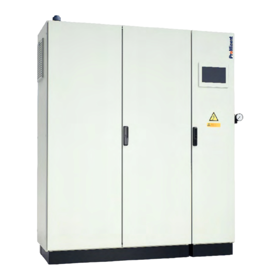
About the product About the product A3468 Fig. 1: DULCOZON OZLa The DULCOZON OZLa series of ozone generation systems is designed as a pressurised system. The feed gas, oxygen, is fed to the ozone generator under pressure in the system. The electronic power unit provides extensive protection for the electrical components (high-voltage transformer and power stage) and also permits the correct digital display of the ozone output in... -
Page 7: Nameplate
About the product 1.2 Nameplate A3540 Fig. 2: Nameplate... -
Page 8: Identity Code
06 6 08 8 12 12 16 16 Feed gas: Oxygen Design: ProMinent Non-standard Cooling: None Control cabinet air conditioning Mechanical design: Standard control cabinet / with packaging for transport by truck Standard control cabinet / with packaging for sea/air freight... - Page 9 Identity code 2 Modbus TCP 3 Modbus RTU 4 Profibus DP 5 Profinet Additional options: None Gas control valve Ozone measuring unit Gas control valve + ozone measuring unit Certification: Tab. 2: Explanation of the identity code: Mechanical design: With designs 0 and 1, the system is installed in a standard powder- coated steel control cabinet.
-
Page 10: Safety
Safety Safety 3.1 Labelling of safety information Identification of safety notes The following signal words are used in these operating instructions to denote different levels of danger: Signal word Meaning DANGER! This combination of symbol and signal word indicates an imme‐ diate dangerous situation that will result in death or serious injury if it is not avoided. - Page 11 Safety The warning information and notes are categorised according to the following scheme. A number of different symbols are used to denote different situations. The symbols shown here serve only as examples. DANGER! Nature and source of the danger Consequence: Fatal or very serious injuries. Measure to be taken to avoid this danger.
-
Page 12: User Qualification
3.5 Intended use The system is intended solely for generating and metering an ozoniferous gas mixture from oxygen. All other uses or a modification of the system are only per‐ mitted with the written authorisation of ProMinent GmbH, Hei‐ delberg. -
Page 13: Safety Equipment
Safety Do not operate the system in conditions other than those described in this document. The system is not intended for operation outdoors. The system is not intended for portable operation. The correct and proper operation of the system cannot be guaranteed if non-genuine parts or third-party accessories are used. -
Page 14: Components Of The System And Their Function
Components of the system and their function Components of the system and their function 4.1 Overview of DULCOZON OZLa 01-16 O 24, 40 A3469 Fig. 3: Ozone generation system illustrated by the OZLa 04O with air conditioning and without door Component Function Pressure regulating valve... - Page 15 Components of the system and their function Component Function Master switch The master switch connects or disconnects the system from the supply voltage or from the mains/power supply. Cooling water inlet angle valve The cooling water flow through the ozone generator can be adjusted using the angle valve.
- Page 16 Components of the system and their function A3470 Fig. 4: Ozone generation system OZLa with mixing unit and without air conditioning Ozone outlet 30 Water mixed with ozone 10 Cooling water outlet 31 Mixing section (accessory) 25 Cooling water inlet 32 Must be fitted vertically pointing downwards.
- Page 17 Components of the system and their function A3481 Fig. 5: Schematic pneumatic and hydraulic flow in the ozone generation systems OZLa 01-16 O for use with oxygen as feed gas Ozone generator block 30 Raw water outlet Ozone generator 31 Mixing section (accessory) Pressure regulating valve with manometer 33 Check valve at the point of injection Adjustable feed gas throttle valve...
-
Page 18: Description Of The Ozone Generation System And Accessories
Components of the system and their function 63 Water trap with liquid level sensor (accessory) II. Oxygen supply, external Extendible to up to 16 modules 4.2 Description of the ozone generation system and accessories Type OZLa ozone generation systems are designed for operation with pure or enriched oxygen as the feed gas. -
Page 19: Door Safety Switch
Components of the system and their function A flow detector with minimum contact can be connected to an input. The flow detector sends a signal to the control to switch off the system when the flow of raw water becomes too low. The system must also be locked by the water treatment system cir‐... -
Page 20: Process Gas Flow
Components of the system and their function 4.4 Process gas flow OZLa 01-16 O The pressure regulating valve (27) at the gas inlet of the system is supplied with compressed, dry oxygen. The system priming pres‐ sure can be adjusted at the pressure regulating valve (27) and read off on the manometer. -
Page 21: Scope Of Delivery, Storage And Transport
Scope of delivery, storage and transport Scope of delivery, storage and transport User qualification: Scope of delivery, storage and transport: Ä Chapter 3.4 ‘User qualification’ trained personnel on page 12 5.1 Scope of delivery Minimum scope of delivery Control cabinet. Operating instructions. -
Page 22: Transport
Scope of delivery, storage and transport 5.3 Transport Incorrect transportation of the system using non-seaworthy wooden crates or horizontal wooden crates. It is essential that the following instructions are adhered to. CAUTION! Toppling of the system cabinet – Once it has been unpacked, secure the system with lashing straps to prevent it from toppling over. -
Page 23: Assembly And Installation
Assembly and installation Assembly and installation User qualification, installation: trained and qualified personnel Ä Chapter 3.4 ‘User qualification’ on page 12 User qualification, hydraulic installation: trained and qualified Ä Chapter 3.4 ‘User qualification’ on page 12 personnel User qualification, electrical installation: electrical technician Ä... - Page 24 Assembly and installation Non-binding recommendations regarding the suitability of the sys‐ tem's installation place: The relevant regulations governing the use of ozone for water ‘GUV 18.13’ treatment (in Germany ZH 1/474 and among others) prescribe that ozone generation systems must be accommodated in sealed rooms, to which only authorised personnel have access.
-
Page 25: Requirements Relating To System Components
(at the point of injection). ProMinent uses stainless steel or PVC mixing modules, with inte‐ gral check valve made of high-alloy stainless steels. The check valve prevents damage to the system, which can be caused by the backflow of raw water into the gas system. -
Page 26: Ozone Removal From Filters And Reaction Section
Assembly and installation For reasons of safety, the length of the pipe and the number of removable connections should be limited to a minimum. In accordance with the safety regulations applicable in Germany, a gas detector is required in every room in which there is a removable gas pipe connection. -
Page 27: Raw Water Pipes
Assembly and installation Place the system on a flat surface, once the packaging mate‐ rial has been removed, and support the control cabinet in such a way that it cannot topple over. Then ensure that all systems are freely accessible for service and maintenance. -
Page 28: Cooling Water System
Assembly and installation The "Technical data" chapter includes information on connection fittings and pressure ranges. 6.4.4 Cooling water system The cooling water connectors are connected using PE hoses. INFORMATION! A filter release valve is needed upstream of the cooling water inlet if the cooling water supply is susceptible to sig‐ nificant fluctuations in pressure or if it is contaminated. -
Page 29: Electrical Installation
Electrical installation Electrical installation User qualification, electrical installation: electrical technician Ä Chapter 3.4 ‘User qualification’ on page 12 7.1 Information regarding electrical connections INFORMATION! Always insert the mains cable at the bottom right; insert all other electric cables (signal leads) through the top of the control cabinet. -
Page 30: Electrical Inputs And Outputs Of The System
Electrical installation 7.2 Electrical inputs and outputs of the system The system has the following inputs and outputs, which are avail‐ able to the user to control and manage the generation of ozone - see the wiring diagram in the Appendix: "Pause"... -
Page 31: Commissioning
Commissioning Commissioning User qualification, commissioning: trained and qualified per‐ Ä Chapter 3.4 ‘User qualification’ on page 12 sonnel Preliminary tests Perform a functional test once the system has been installed to check for any possible damage that could have been caused during transportation. - Page 32 Commissioning Ensure that the value "0%" is displayed as the setting for "Ozone". Use the N key to adjust the ozone control variable to 0% if necessary. In this setting, the high-voltage generator is deactivated and no ozone is generated. [START] / [STOP] key.
-
Page 33: Setting The Gas Priming Pressure
Commissioning During commissioning, the personnel responsible for the ozone generation system must be instructed on the ope‐ ration of the system, as well as on its measuring tech‐ nology (calibration of sensors etc.). They must also be trained in all safety-related issues. The responsible personnel must have access to these operating instructions and to all safety information. -
Page 34: Setting The Cooling Water Flow
Commissioning 8.5 Setting the cooling water flow The following settings need to be made when the system is run‐ ning with the cabinet door open. Wait at least 5 minutes after the supply of power to the system has been interrupted by the mains switch before touching the components inside the cabinet. -
Page 35: Operation
Operation Operation Ä Chapter 3.4 ‘User User qualification, operation: trained user qualification’ on page 12 The system is switched on by turning the master switch (19) to position "1". The master switch (19) is located on the right-hand side of the control cabinet. 9.1 Touch panel You can use the touch panel to: Start or stop the entire system,... -
Page 36: Operating Keys And Control Information
Operation 9.2 Operating keys and control information A number of keys are provided to operate the system, which are shown at the lower edge of the touch panel. Operation with ozone Start Ozone A3473 Fig. 7: System information and operating keys Back key 10 Display: High voltage on [MENU] key... -
Page 37: Displays On The Process Screen
Operation 9.3 Displays on the process screen The touch panel displays the components involved in the process: Operation with ozone Start Max. modules Active Ozone A3474 Fig. 8: Process screen Control valve (optional) or needle valve to set the feed gas flow Ozone generator Ozone outlet Ozone outlet solenoid valve... -
Page 38: Log In/Log Out. User: Expert
Operation The authorisation scheme is arranged according to users and incorporates the keyboard lock. The following users are set up for the operator: ‘OPERATOR’ user is automatically activated once the system has been switched on without any further action being required. ‘OPERATOR’... -
Page 39: Operating Modes And Settings
Operating modes and settings Operating modes and settings 10.1 Operating modes Operation Mode Operation Mode Remote monitoring Local Warn ALARM Operation Remote Intern Setpoint Intern Oxygen Sensor type Interface A3479 Fig. 10: Operating modes The system has the following operating modes: Internal External Local 0/4 ... -
Page 40: Gas Flow Mode (Optional)
Operating modes and settings 10.2 Gas flow mode (optional) Setpoint Operation Mode Standard Constant Reset Gasflow Constant ozone concentration Gasflow Min. Gasflow Max. A3480 Fig. 12: Gas flow mode (optional) The following operating modes can be selected for the gas flow control valve: ‘... -
Page 41: Key System Statuses
Operating modes and settings Setpoint Operation Mode Standard Constant Gasflow Constant Reset ozone concentration Gasflow Min. Gasflow Max. A3482 Fig. 14: ‘Operation Mode’ ‘Constant ozone concentration’ The control valve is in operation. The ozone concentration is regu‐ lated. You can enter the setpoint for the ozone concentration in the ‘Setpoint’... -
Page 42: Error" Operating Status
Operating modes and settings 10.3.3 "Error" operating status [STOP] Once an error has occurred, the system is switched to operating status by the control. The gas inlet and outlet are closed by a solenoid valve. The cooling water inlet is closed by a solenoid valve. The high voltage required for ozone generation is switched off. -
Page 43: Behaviour Of The System When Power Is Connected
Operating modes and settings [PAUSE] message appears in the status bar of the touch [PAUSE] signal has been cleared, the system runs panel. Once the without further action in the operating status it was in before the PAUSE input was activated. 10.4 Behaviour of the system when power is connected The control (12) determines the behaviour of the system when... -
Page 44: Displays On The Touch Panel
Displays on the touch panel Displays on the touch panel 11.1 Total system displays The following functions and displays can be seen in normal opera‐ tion, if: The system’s master switch is set to ON. The fuse inside the system has not been triggered. The system's priming pressure is within the permissible range. -
Page 45: Pressure In The Ozone Generator
Displays on the touch panel 11.2.5 Pressure in the ozone generator The gas pressure for ozone generation is monitored by the pres‐ sure sensor (6) and displayed on the touch panel. The pressure relief valve (8) limits the pressure to non-critical values. The actual gas pressure in the ozone generator depends on: The process water pressure at the point of injection. -
Page 46: Primary Voltage
Displays on the touch panel 11.3.6 Primary voltage The display indicates the voltage at the primary side of the high voltage transformer. The measured value displayed depends on the "control variable" set and the operating pressure displayed on the pressure sensor (6) in the system cabinet. 11.4 Status page The following values can be displayed here:... -
Page 47: Maintenance
Maintenance Maintenance User qualification, maintenance/repair: trained and qualified Ä Chapter 3.4 ‘User qualification’ on page 12 personnel 12.1 Safety guidelines for maintenance and repair Only allow trained and qualified personnel to service or repair the system. Ensure that persons who undertake maintenance and repair work on the system have read and understood the operating instructions and in particular the "Safety"... -
Page 48: Regular Maintenance
Maintenance Display values Value Unit Remark Interval Primary current daily Operating hours daily Operating hours with ozone daily Power ons daily Error messages daily Other parameters Cooling water flow daily Ozone generator pressure less than daily Other checks Check the filter mats in the ozone depending on ambient monthly cabinet... -
Page 49: Maintenance Of The Air Conditioning Unit
Maintenance 12.4 Maintenance of the air conditioning unit Refer to the operating instructions for the air conditioning unit for information on maintenance with systems fitted with an air condi‐ tioning unit. -
Page 50: Troubleshooting
Troubleshooting Troubleshooting Ä Chapter 3.4 User qualification, troubleshooting: trained user ‘User qualification’ on page 12 WARNING! – Disconnect the system from the supply voltage before starting troubleshooting or fault rectifica‐ tion work on the system. – Wait at least 5 minutes after the system has been disconnected from the mains/power supply before touching components inside the cabinet. -
Page 51: Fault
Troubleshooting The "alarm delay" is the time period between a fault being detected and the system being switched off. The time is based on the type of limit violation. Once the system has been switched off, the fault indicating relay is activated and the operating signal relay is deacti‐ vated. -
Page 52: Error Table
Troubleshooting 13.3 Error table Error* Error message Switch-off due Cause Remedy to... 10003 Invalid activation Activation code Enter a correct activation code. code entered incorrectly 10004 System tempera‐ Temperature The temperature in Check that the control cabinet fan is ture too high sensors in the the control cabinet working correctly. - Page 53 Troubleshooting Error* Error message Switch-off due Cause Remedy to... 10023 External setpoint Setpoint outside the Check and set the setpoint too low permissible limit values 10024 External setpoint Setpoint outside the Check and set the setpoint too high permissible limit values 10026 Check the flow...
- Page 54 Troubleshooting Error* Error message Switch-off due Cause Remedy to... 10061 Water trap full The external Water penetrates Do not start up the system with water trap from the point of ozone. There is a threat of major (optional) injection into the material damage.
- Page 55 11012 PFC voltage too high 11017 FC 1 power consumption too high A fault in the Contact In the power elec‐ power elec‐ ProMinent 11018 FC 2 power consumption too tronics. tronics. Service. high 11019 FC 1 voltage too low...
-
Page 56: Technical Data
Technical data Technical data 14.1 Complete system Ambient parameters Parameter Value Maximum ambient temperature without air conditioning unit 40 °C Maximum ambient temperature with air conditioning unit 50 °C Relative humidity, non-condensing maximum 85% Air quality: dust-free and non-corrosive. 14.1.1 OZLa 1-3 O (oxygen as the feed gas) Ozone generation sys‐... - Page 57 Technical data Ozone generation sys‐ Unit OZLa 01 O OZLa 02 O OZLa 03 O OZLa 04 O tems Weight Weight approx. Ozone mixing unit Max. raw water tem‐ °C perature Permissible pressure at 0.8 ... 2.0 0.8 ... 2.0 0.8 ...
-
Page 58: Ozla 06-16 O (Oxygen As The Feed Gas)
Technical data 14.1.2 OZLa 06-16 O (oxygen as the feed gas) Ozone generation sys‐ Unit OZLa 06 O OZLa 08 O OZLa 12 O OZLa 16 O tems Ozone generation systems Number of generation modules Output at 100 g/Nm and cooling water: 15 °C... -
Page 59: Power Supply To The System
Technical data Ozone generation sys‐ Unit OZLa 06 O OZLa 08 O OZLa 12 O OZLa 16 O tems Gas volume at an output of 200 g/Nm Min. concentration vol% Max. dewpoint °C Pressure 3 ... 6 3 ... 6 3 ... -
Page 60: Wiring Diagram
Technical data Tab. 5: Electrical inputs and outputs of the OZLa02-16 Parameter Value Mains frequency 50/60 Hz Nominal voltage 400 V +/- 10% Connection to L1, L2, L3, N, PE Please refer to the terminal and wiring diagrams in the Appendix for all further information. 14.3 Wiring diagram The wiring diagram can be found in the Appendix. -
Page 61: Accessories
Accessories Accessories 15.1 Classification Compulsory accessories: Ozone detector Recommended accessories, available on request: Oxygen detector Mixing unit with check valve Residual ozone destruction unit Oxygen supply – System for enriching oxygen from ambient air and com‐ pressor or – Oxygen bottles or –... - Page 62 Accessories Tab. 9: Material 1.4404 Flow Length Connector Order no. 5 – 10 DN40 1022503 10 – 15 DN50 1022514 15 – 25 DN65 1022515 25 – 35 1100 DN80 1022516 35 – 50 1100 DN100 1024154 Other sizes on request. Tab.
-
Page 63: Dimensional Drawing
Dimensional drawing Dimensional drawing 16.1 DULCOZON OZLa 01+02O 1214 1595 A3471 Fig. 15: Dimensional drawing: DULCOZON OZLa 01+02O all dimensions in millimetres... -
Page 64: Dulcozon Ozla 03+04O
Dimensional drawing 16.2 DULCOZON OZLa 03+04O 1326 0 98 1214 1966 1903 1773 1723 1300 1180 T = 260 (OZLa 03O) T = 310 (OZLa 04O) 80_00-401_01_11-7A A3536 Fig. 16: Dimensional drawing: DULCOZON OZLa 03+04O, all dimensions in millimetres... -
Page 65: Dulcozon Ozla 06+08O
Dimensional drawing 16.3 DULCOZON OZLa 06+08O 1723 0 104 1141 1611 1976 1902 1768 1718 1300 1174 T = 294 (OZLa 06O) 80_00-401_01_10-7A T = 393 (OZLa 08O) A3537 Fig. 17: Dimensional drawing: DULCOZON OZLa 06+08O, all dimensions in millimetres 16.4 DULCOZON OZLa 12+16O 0 104... -
Page 66: Operating Report
Operating report Operating report Fig. 19: Operating report... -
Page 67: Eu Declaration Of Conformity
EU Low Voltage Directive (2006/95/EU) EU EMC Directive (2004/108/EU) EU Pressure Equipment Directive (97/23/EU) Harmonised standards applied, EN 60204-1 in particular: EN 61010-1 EN 60529 EN 61000-3-2/3 EN 61000-6-2/4 EN 60664-1 Place/date: Heidelberg, 22.09.2021 Download the Declaration of Conformity at www.prominent.com. -
Page 68: Information On The Legally Compliant Use Of Ozone
Below a production volume of 1 t/year (= 114 g/h continuous output), no registration is required. For further information, please contact EurO zon at: www.euro3zon.org/LoA/IndexReach . ProMinent GmbH, member of EurO zon ivzw... -
Page 69: Index
Index Index Oxygen quality ......56 Ozone detector ......61 Accessories . - Page 72 ProMinent GmbH Im Schuhmachergewann 5-11 69123 Heidelberg Germany Telephone: +49 6221 842-0 Fax: +49 6221 842-419 Email: info@prominent.com Internet: www.prominent.com 990175, 1, en_GB © 2022...
Need help?
Do you have a question about the OZLa 06 O and is the answer not in the manual?
Questions and answers