Table of Contents
Advertisement
Quick Links
Operating Instructions
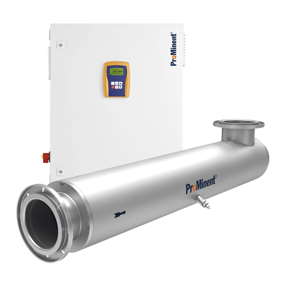
Dulcodes R
UV System with Manual Wiper
Dulcodes 1 x 300 R
Please affix the type identification label here!
Please completely read through the operating instructions first! Do not discard!
Damage caused by operating errors will invalidate the guarantee!
Part No. 986671
ProMinent Dosiertechnik GmbH · 69123 Heidelberg · Germany
BA DS 008 07/06 GB
Advertisement
Table of Contents

Related Manuals for ProMinent Dulcodes R


Summary of Contents for ProMinent Dulcodes R
- Page 1 Please affix the type identification label here! Please completely read through the operating instructions first! Do not discard! Damage caused by operating errors will invalidate the guarantee! Part No. 986671 ProMinent Dosiertechnik GmbH · 69123 Heidelberg · Germany BA DS 008 07/06 GB...
- Page 2 Disregard of the safety information may result in the risk of damage to property! NOTE! Information on disposal. IMPORTANT! Working information. Imprint: Operating instructions - Dulcodes R UV System with Manual Wiper © ProMinent Dosiertechnik GmbH, 2006 Address: ProMinent Dosiertechnik GmbH Im Schuhmachergewann 5-11 69123 Heidelberg Germany info@prominent.com...
-
Page 3: Table Of Contents
Troubleshooting ................. 38 Technical Data .................. 40 Performance Data ................40 Dimensions ..................41 Electrical Data ..................42 Annex ......................43 Spare Part Drawings ................... 43 Spare Parts List ....................45 Terminal Connection Diagram – Dulcodes R ............46 Page 3... -
Page 4: Ec Declaration Of Conformity
EC Declaration of Conformity Page 4... -
Page 5: Application/Use
Chloramines in swimming pool water, for instance, are reliably degraded as part of the photo- chemical treatment process. Dulcodes R UV systems feature a manual wiper for the purpose of cleaning the protective tubes for the UV lamps. Dulcodes UV systems are turnkey systems ready for connection. -
Page 6: Safety Devices
Safety / Function IMPORTANT! Take note of the technical datasheet supplied with the respective UV system! Observe the supplementary instructions for special applications, in which the sensor signal is displayed in %! Safety Devices Label on radiation chamber CAUTION! Dangerous ultraviolet radiation o UV-C radiation is harmful to the eyes and skin! Place the UV lamps into operation only in UV-C their installed state! Install the UV system in accordance with regulations and instructions... -
Page 7: Control
Function / Control The shut-off valve opens after start-up flushing. The UV system assumes normal operation. Normal operation The UV-C sensor still monitors the UV-C output during normal operation: UV-C output drops below the warning threshold: A warning is triggered. UV-C output drops below the safety threshold: The shut-off valve closes and the flushing valve opens. -
Page 8: Function Keys
Control Function Keys START/STOP To switch the UV system ON and OFF CHANGE In operating mode: Change display window In programming mode: Change adjustable parameters BACK Move one level back in menu DOWN In programming mode: Decrease an indicated numerical value Change a data item In programming mode: Increase an indicated numerical value... -
Page 9: Operating Status Display And Parameter Setting
Control Operating Status Display and Parameter Setting Analogue output 100 W/m xxxx h Operation x W/m = y mA Standard display xxxx - times ON xxx W/m = yy mA Display change Trend display Pump control Version Start-Up UVAS - A1 Flushing time FW 02.01.00 x min... -
Page 10: Trend Display
Control Programming instructions (Adjustable values/ Memory display (Enable code query) settings flash) 1 sec Changes are not stored Changes are stored Incorrect enable code Return to display window IMPORTANT! Once the enable code has been entered correctly, it is no longer necessary to re-enter the code during further programming procedures. -
Page 11: Changing Enable Code
Control 4.3.2 Changing Enable Code To prevent unauthorised changes to the settings, the system control has an enable code for programming mode. This code can be freely selected by the operator. Programming mode is still disabled after changing the enable code. The disable is cancelled only after entering the new enable code. -
Page 12: Setting Uv Lamp Current
Control 4.3.5 Setting UV Lamp Current Lamp current = 3.5 A (min. 3.0 A) (max. 3.5 A) The lamp current can be freely selected within a defined range in connection with ballasts that feature a bus interface. This adjustment makes it possible to adapt the UV lamps to specific operating conditions. -
Page 13: Sensor Calibration
Control 4.3.7 Sensor Calibration 100 W/m Cal. factor = 1.000 Time 5:00 The UV-C sensor is calibrated at the factory and does not need recalibration. 4.3.8 Setting Trend Display Range Display range Trend display 100 day(s) The recording time of the sensor signal for the trend display can be adjusted. The value (in days) is interpreted as a time window and therefore guarantees a continuous display: After the selected time has elapsed, the oldest value is deleted and the new value displayed. -
Page 14: Setting Warning Threshold
Control 4.3.10 Setting Warning Threshold 55.0 W/m Warning threshold A warning is triggered if the UV-C output decreases to such an extent that the sensor signal drops below the warning threshold. The lamp protection tubes should be cleaned or the lamps replaced or the water quality improved by suitable preparation in order to avoid the signal dropping below the safety threshold. -
Page 15: Activating Pump Control
Control 4.3.12 Activating Pump Control Pump control The pump control must be activated in order to drive a delivery pump with the pump relay. The pump relay is in dropped-out state when the system is switched off and remains in dropped-out state with the pump control “OFF”... -
Page 16: Setting Maximum Clear Flushing Time
Control 4.3.14 Setting Maximum Clear Flushing Time Maximum clear flushing time 00:01 h:min Clear flushing is mainly used for drinking water disinfection where maximum clear flushing times of more than 10 hours are often implemented. The shut-off valve will close and the flushing valve open if, for example, the UV transmission in ground water or spring water deteriorates after heavy rainfall to such an extent that the UV-C sensor signal drops below the safety threshold. -
Page 17: Setting Minimum Mains Voltage
Control 4.3.17 Setting Minimum Mains Voltage Minimum mains voltage 180 V Monitoring the mains voltage prevents uncontrolled failure of the UV system and of the lamps due to excessively low mains voltage. If the mains voltage drops below the minimum value, the control assumes the undervoltage state and shuts down the system. -
Page 18: Alarm Signalling Relay
• ProMinent shall reject any warranty claims or claims for compensation in the event of damage during emergency operation of the UV system. -
Page 19: Assembly And Installation
Assembly and Installation Assembly and Installation Detail X Detail Y Fig. 2: Design of radiation chamber with details X and Y 1 Knob 2 Clamping screw 3 Chamber cover 4 O-ring 5 Outlet 6 Centring pin 7 Vent/discharge (depending on installation position) 8 Securing element 9 UV sensor 10 O-ring... -
Page 20: Radiation Chamber
Assembly and Installation Please take note of the following safety information prior to installation: WARNING! Make sure that • the maximum permissible water flow rate is not exceeded and • the UV transmission does not drop below the minimum permissible levels otherwise adequate treatment will no longer be guaranteed! The maximum permissible water flow rate is defined in the supplied datasheet. -
Page 21: Affixing Warning Sign
Assembly and Installation 5.1.3 Affixing Warning Sign IMPORTANT! Affix the supplied self-adhesive warning sign such that it is clearly visible on the radiation chamber. 5.1.4 Hydraulic Connections ATTENTION! • Make the hydraulic connection of the radiation chamber in accordance with valid general guidelines as well as the locally applicable installation regulations. -
Page 22: Opening Control Unit
Assembly and Installation • Connect a PE conductor to the radiation chamber and to the chamber cover! • Secure the power supply by means of a suitable residual current-operated circuit breaker! • Only an authorised electrician is permitted to open the control cabinet! •... -
Page 23: Installing Lamp Protective Tubes
Assembly and Installation 1 PG-11 screwed gland 2 Metal ring 3 Rubber seal Fig. 4: Cable leadthrough – rear row 4 PG-7 screwed gland 5 Lock nut Fig. 5: Cable leadthrough – front row Installing Lamp Protective Tubes ATTENTION! Take particular care during this work to ensure that the extended wiper rod is not bent! 1 Knob 7 Chamber cover 2 Guide pin... -
Page 24: Installing And Connecting Uv Lamps
Assembly and Installation ➤ Slacken off the clamping screw a little (approx. 1/4 turn in counterclockwise direction) ➤ Release the fixing bush out of the lock of the clamping screw ➤ Pull the wiper rod as far as it will go – it must remain against the stop until it is inserted again! ➤... -
Page 25: Installing And Connecting Uv-C Sensor
Assembly and Installation ➤ Check to ensure that the O-ring on the retaining fixture for the lamp protective tube is fitted in the groove provided for this purpose – the sealing surfaces of the O-ring must be completely smooth and clean! ATTENTION! When fitting the UV lamps, turn them such that the two connected cables face away from the UV sensor! -
Page 26: Start-Up
Calibrating UV-C Sensor The UV-C sensor is calibrated at the factory and does not need recalibration. If recalibration is required, please send the system in to ProMinent. IMPORTANT! Observe the supplementary instructions for special applications, in which the sensor signal is displayed in %. -
Page 27: Maintenance
Maintenance Maintenance Maintenance of the UV system is restricted to cleaning the lamp protective tubes and the sensor window replacing the wiper elements and O-ring of the clamping screw as well as to replacing the UV lamps at the end of their maximum permissible useful life. In the case of systems that have a fan installed in the control cabinet, the filter mats of the fan and the air outlet filter in the control cabinet should be replaced at regular intervals (normally once a year). -
Page 28: Cleaning With Manual Wiper
Maintenance 7.1.1 Cleaning with Manual Wiper CAUTION! • Firmly hold the knob after releasing the fixing bush! The water pressure in the radiation chamber presses the wiper rod with a certain force in the direction of the system operator! • Take particular care during this work to ensure that the extended wiper rod is not bent! 1 Knob 2 Guide pin 3 Fixing bush... -
Page 29: Cleaning After Removing The Lamp Protective Tubes
Maintenance 7.1.2 Cleaning After Removing the Lamp Protective Tubes WARNING! • Switch off the master switch or disconnect the power plug before installation and connecting the UV lamps! • Place the UV lamps into operation only in their installed state! UV-C radiation is harmful to the eyes and skin! Install the UV system in accordance with regulations and instructions before starting up the UV lamps! - Page 30 Maintenance ➤ Slacken off the clamping screw a little (approx. 1/4 turn in counterclockwise direction) (see Fig. 6) ➤ Release the fixing bush out of the lock of the clamping screw ➤ Pull the wiper rod as far as it will go – it must remain against the stop until it is inserted again! ➤...
-
Page 31: Cleaning With Cleaning Solution
Maintenance 7.1.3 Cleaning with Cleaning Solution Cleaning the lamp protective tubes by filling the radiation chamber with a cleaning solution: ➤ Switch on UV system with the START/STOP key ➤ Switch off master switch or disconnect power plug ➤ Close shut-off valves upstream and downstream of the radiation chamber ➤... -
Page 32: Replacing Wiper Elements
Maintenance Replacing Wiper Elements WARNING! • Switch off the master switch or disconnect the power plug before installation and connecting the UV lamps! • Place the UV lamps into operation only in their installed state! UV-C radiation is harmful to the eyes and skin! Install the UV system in accordance with regulations and instructions before starting up the UV lamps! ATTENTION! - Page 33 Maintenance 1 Knob 2 Guide pin 3 Fixing bush 4 Clamping screw Fig. 10: Parts of the manual wiper at the chamber cover 5 Wiper rod 6 O-ring 7 Chamber cover ➤ Slacken off the clamping screw a little (approx. 1/4 turn in counterclockwise direction) ➤...
-
Page 34: Replacing O-Ring On Clamping Screw
Maintenance ATTENTION! • Before installing, check the lamp protective tube for damage! A damaged protective tube must not be reinstalled. • Make sure the protective tube is fitted correctly! The lamp protective tube may protrude by a maximum of 40 mm and exhibit no angle offset! ➤... -
Page 35: Changing Uv Lamps
Maintenance ➤ Clean the wiper rod if necessary ➤ Replace the O-ring ➤ Reinstall clamping screw but do not tighten ➤ Use a WAF 11 open-ended spanner to secure the knob (with fixing bush) onto the wiper rod ATTENTION! The seal of the wiper rod may be easily damaged! Make sure the surface of the wiper rod is clean before reinserting it in the radiation chamber! ➤... - Page 36 Maintenance INFORMATION FOR MULTI-LAMP SYSTEMS • All UV lamps must be replaced when changing the lamps at the end of their maximum useful life. • All UV lamps must be replaced when changing the lamps due to ageing. • Only new UV lamps should be used to replace defective lamps. •...
-
Page 37: Calibrating Uv-C Sensor
Maintenance IMPORTANT! With the system shut down, plug the connector together with the lamp cover onto the lamp before inserting the lamp in the protective tube. ➤ Insert the lamp in the protective tube and leave protruding by approx. 100 mm ➤... -
Page 38: Troubleshooting
Maintenance Troubleshooting CAUTION! • Only authorised electricians are permitted to perform troubleshooting operations on the opened control cabinet and replace components! Warning threshold undershot ↓ ↓ ↓ ↓ ↓ 55.0 W/m Indication: Arrow pointing down 10 h Operation ON/OFF Safety threshold undershot ↓... - Page 39 Maintenance Error message: Other fault Fault ➤ Confirm error message with ENTER key Other fault Possible cause External fault signalling device triggered ➤ Rectify external cause of fault Remedy Possible cause No external fault signalling device connected and no jumper is connected across the contacts at the fault input ➤...
-
Page 40: Technical Data
Maintenance / Technical Data Function and Fault Indicators on Ballast Units The three red LEDs on the ballasts serve the purpose of checking function and troubleshooting. All three LEDs light up for approx. 1 second when the supply voltage is applied. LED “Power Supply”... -
Page 41: Dimensions
Technical Data Dimensions Page 41... -
Page 42: Electrical Data
Technical Data Electrical Data Radiation chamber Lamp type: OptiFlux 300 W Lamp current: Standard: 3.5 A Maximum: 3.5 A Minimum: 3.0 A Control Nominal voltage: 230 V AC, 50/60 Hz Fuses: Fine fuse 5 x 20 mm (250 V AC): Upper fuse (control power supply): 0.16 A slow-blow, Order No. -
Page 43: Annex
Spare Part Drawings Annex Spare Part Drawings Only for 3 x 300 R 4 x 300 R DULCOMETER STOP START Only for 3 x 300 R 4 x 300 R Outlet Inlet Fig. 12: Dulcodes R Page 43... - Page 44 Spare Part Drawings Detail X Detail Y Fig. 13: Detail views of wiper (see Fig. 12) Fig. 14: Sectional view through lamp connection and manual wiper Page 44...
-
Page 45: Spare Parts List
Spare Parts List Spare Parts List Description Part number Change Qty. interval Lamp protective tube d40x2x1400mmQ 1020846 As required UV lamp 300 W 1020929 max. 12 000 h 1 - 4 Retaining fixture for lamp protective tube (mount d40 - G 2 - d69) 1026728 As required UVC-U sensor P/D/W/R G 3/4 1028115... -
Page 46: Terminal Connection Diagram - Dulcodes R
Terminal Connection Diagram – Dulcodes R Terminal Connection Diagram – Dulcodes R Page 46... - Page 47 Form – Operation Log Page 47...
Need help?
Do you have a question about the Dulcodes R and is the answer not in the manual?
Questions and answers