Table of Contents
Advertisement
Quick Links
Advertisement
Table of Contents

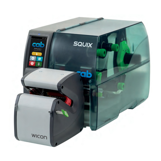
Summary of Contents for CAB WICON SQUIX
- Page 1 Service Manual Wrap-around applicator WICON MADE IN GERMANY...
- Page 2 Edition: 09/2022 - Part No. 9003822 Copyright This documentation as well as translation hereof are property of cab Produkttechnik GmbH & Co. KG. The replication, conversion, duplication or divulgement of the whole manual or parts of it for other intentions than its original intended purpose demand the previous written authorization by cab.
-
Page 3: Table Of Contents
Table of Contents Introduction ............................4 Instructions ............................... 4 General Safety Instructions ........................4 Protective Devices ........................... 5 Handling Electricity ..........................5 Procedure in Case of Accidents ......................5 Environment ............................. 5 Preparation ............................. 6 Tools ................................. 6 Removing the Applicator from the Printer ....................6 Removing the Covers .......................... -
Page 4: Introduction
Introduction Instructions Important information and instructions in this documentation are designated as follows: Danger! Draws attention to an exceptionally great, imminent danger to your health or life due to hazardous voltages. Danger! Draws attention to a danger with high risk which, if not avoided, may result in death or serious injury. Warning! Draws attention to a danger with medium risk which, if not avoided, may result in death or serious injury. -
Page 5: Protective Devices
Introduction Protective Devices Warning! There is a risk of injury if protective devices are missing or defective. Replace all protective devices (covers, safety notices, grounding cables etc) after maintenance work has been completed. Replace parts that have become defective or unusable. Wear protective goggles for: •... -
Page 6: Preparation
• Snap ring pliers ZGG 0 • Pointed pliers straight • Belt tension measuring device cab special tools: • Calibration rod 10 mm (Part No. 5988543) Removing the Applicator from the Printer Fig. 1 Removing the applicator from the printer ... -
Page 7: Removing The Covers
Preparation Removing the Covers For a couple of maintenance operations it is necessary the remove the covers from the winding assembly. 2.3.1 Removing the Side Covers Fig. 2 Removing the side covers Loosen the screw (5) and remove the stopper (4). ... -
Page 8: Replacing Assembly Units
Replacing Assembly Units Replacing the Transport Module 1 2 1 4 5 4 Fig. 4 Replacing the transport module Remove the covers Turn the winder plate (3) to the position shown in the figure. Loosen the screw (2) and remove the transport module (6). The screw (2) is secured and remains in the winding plate. -
Page 9: Replacing The Centering Panels
Replacing Assembly Units Replacing the Centering Panels Centering panel gear side Centering panel winder side Fig. 6 Replacing the centering panels Remove the covers. Loosen two screws (1) and washers (2) and remove the centering panel (3). Disconnect the cable (5) from the PCB (4). ... -
Page 10: Replacing The Guard Plate
Replacing Assembly Units Replacing the Guard Plate Fig. 7 Replacing the guard plate Remove the covers and the centering panel at the gear side. Loosen two screws (3). Loosen two shoulder screws (1a,1b) and remove the guard plate (4). ... -
Page 11: Replacing The Belt
Replacing Assembly Units Replacing the Belt Fig. 9 Replacing the belt Remove side cover, centering panel and guard plate at the gear side Pull the belt (1) from the gear wheels (2-6). Push the new belt onto the gear wheels. Fig. -
Page 12: Replacing The Cam Plate And The Locking Lever
Replacing Assembly Units Replacing the Cam Plate and the Locking Lever Fig. 11 Replacing the cam plate Remove covers and centering panels. Loosen two screws (8) and remove the plate (7). Loosen two screws (1) and pull the winder plate (4) with the cam plate (3) and the transport module (6) out of the housing. -
Page 13: Replacing The Pcb Control
Replacing Assembly Units Replacing the PCB Control Fig. 13 Replacing PCB Control Loosen four screws (1). Pull-out all cables from the connectors of the PCB Control (2). Pull the PCB Control out of the housing. Mount the new PCB in the opposite order. Fig. -
Page 14: Adjustments
Adjustments Adjusting the Centering Panels Note! The applicator must be operated with the printer to adjust the centering panels. Checking Switch on the system Insert the calibration rod 10 mm (1 / Part No. 5988543). Turn the winder plate by pressing the single-step key and observe the hunting of the rod. -
Page 15: Calibrating The Diameter Recognition
Adjustments Calibrating the Diameter Recognition Switch on the system. Start menu. Setup > Labelling > Calibrate device. Select Insert the calibration rod 10 mm (Part No. 5988543). Select Continue. The wrapping unit will be turned ten times with closing and opening the jaws and measuring the diameter of the test pipe. -
Page 16: Error Treatment
Error Treatment Note! The following table describes the reasons for error messages which occur repeatedly or permanently. Message Error/Reasons Remedy Touch guard error Failure of the touch guard movement Adjust the shoulder screws • Shoulder screws at the guard plate tightened to hard ... -
Page 17: Block Diagram
Block Diagram Service Button Periphery 5555158 5907838 PCB Sensor Centering L Sensor Applicator locked 5907839 5551423 5555159 PCB Sensors Ref.+Diam. 5551621 5555199 5555155 PCB Control 5555138 Motor Guard 5555157 5555198 PCB Touchgard Sensor PCB Sensor Centering R 5555156 5907839 5551619 5551423 Motor Winder 5988151... -
Page 18: Index
Index Belt ........... 11 Block diagram ........17 Cam plate .........12 Centering panels Adjusting ........14 Replacing ........9 Covers ..........7 Diameter recognition ......15 Error treatment .........16 Guard Plate ........10 Important information......4 Locking lever ........12 PCB Control........13 PCB Sensor Labels ......8 Safety instructions ......4 Service door ........7 Shoulder screws .......10 Tools ...........6...


Need help?
Do you have a question about the WICON SQUIX and is the answer not in the manual?
Questions and answers