Advertisement

Quick Links

Documentation Center
RAK7249 Quick Start Guide
Prerequisites
What Do You Need?
1. RAK7249 WisGate Edge Max
2. A Windows/Mac OS/Linux Computer
WARNING
The SIM card slot of the cellular versions is not hot-swappable. Make sure the gateway is switched off
before inserting or ejecting the SIM card.
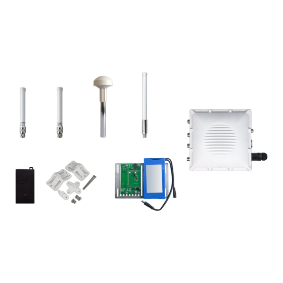
What's Included in the Package?
NOTE
The included type and number of antennas and the Backup Battery Kit is optional, depending on the
purchased bundle.
Product Configuration
Gateway Installation Guide
For details about the interfaces and connectors of RAK7249 WisGate Edge Max Gateway enclosure, refer to the
Datasheet.
Assembly
1. Fix the support plate on the base with three M3*6 screws.
Figure 1: RAK7249 Package Contents

Advertisement

Table of Contents
loading

Summary of Contents for RAK WisGate Edge Max

  • Page 1 The included type and number of antennas and the Backup Battery Kit is optional, depending on the purchased bundle. Product Configuration Gateway Installation Guide For details about the interfaces and connectors of RAK7249 WisGate Edge Max Gateway enclosure, refer to the Datasheet. Assembly 1. Fix the support plate on the base with three M3*6 screws.
  • Page 2 Documentation Center Figure 2: Fixing the support plate 2. Install the motherboard with four M3*6 screws. Figure 3: Installing the motherboard 3. Install the LoRa card. The motherboard supports two LoRa cards. Slot one supports only SPI type, and slot two supports only USB type.
  • Page 3 Documentation Center Figure 5: Installing the cables and plugs 6. Connect the cables to the motherboard. The connectors on the motherboard are shown in Figure 6. Figure 6: Connecting the cables to the motherboard NOTE You must use the Wi-Fi MAIN connector to connect the Wi-Fi antenna. 7.
  • Page 4 Documentation Center Figure 8: Fixing the battery 10. Fix the four M3*30mm hexagon spacers on the bottom plate. Figure 9: Adding Spacers 11. Connect the cables as shown in Figure 10. Connect the PH2.0 socket on the motherboard and the charging PCB board with the 2pin signal cable. Connect the DC socket of the charging PCB board and the battery socket with a DC Plug cable.
  • Page 5: Installation

    Documentation Center Figure 11: Fixing the Charge Module 13. Close the top cover with M4*12 screws. Make sure that the rubber seal is placed correctly in the groove between the box and the lid to prevent leaks. Figure 12: Closing the enclosure Installation Instructions on mounting and securing the mounting kit to the enclosure and the bearing pole.
  • Page 6: Weather Protection

    Documentation Center Figure 14: Mounting the clamp to the pole 3. Connect the pole clamp and the cross bracket by securing the last piece of the mounting kit in place using M6*30 bolts, washers, and nuts. Figure 15: Fixing the enclosure to the pole clamp Weather Protection To better protect the Ethernet cable gland and the antenna connector from the weather, you need to cover them with PVC tape.
  • Page 7: Package List

    Documentation Center 2. Cut off about 50 cm waterproof tape. Stretch it to double the length. Wrap three layers around the connector with a 50% overlap. Hold the tape in place with your hand for a few seconds. Figure 17: Wrapping with waterproof tape 3.
  • Page 8: Specifications

    Documentation Center Figure 19: Solar Panel and Battery Kit Installation Package List Specifications Solar Panel 1. Dimensions The dimension of the Solar Panel included in the kit is 665 x 815 millimeter. Provided in the image below are the detailed dimensions of the solar panel for extended functions. Figure 20: Solar Panel Dimensions 2.
  • Page 9: Lithium Battery

    Documentation Center Maximum Power (Pmax) Maximum Power (Pmax) 80 Watts 80 Watts Voltage at Pmax (Vmp) 18 Volts Current at Pmax (Imp) 2.2 - 5.5 Amperes Open Circuit Voltage (Voc) 21.6 Volts Short Circuit Current (Isc) 2.3-6.5 Amperes Lithium Battery 1.
  • Page 10 Documentation Center Figure 21: H-Shaped Nuts and Bolts Placement for the Bracket 2. Mount the battery on top of the two parallel rails in the middle. Make sure it is as close as possible to the middle of the construction. Fasten it to the rails with four bolts, each having a washer and a nut. Refer to the image below on how to insert the bolts into the railing that is part of the bottom of the battery casing.
  • Page 11 Documentation Center Figure 23: Lithium Battery Input Cord to Solar Panel Connection 4. The following image then shows where the cable connection between the solar panel entering the input terminal on the battery is performed in Step 3. Figure 24: Lithium Battery to Solar Panel Outside Connection 5.
  • Page 12: Lightning Protection

    In this document, we will be discussing how to set up your lightning surge protection system whether be your RAK7249 WisGate Edge Max situated outdoor or indoor. Such protection system must be taken into consideration to ensure a fully functional Gateway without interruption or damage from the lightings.
  • Page 13: Recommended Equipment

    Documentation Center Figure 27: Full Lighting Protection Set-up Diagram Outdoor Surge Protection System Antenna Grounding RAKwireless recommends a lightning arrestor to be installed on all the antenna N-Type terminals (LoRa, LTE, Wi-Fi and GPS). It is recommended to use a 10-AWG or better grounding wire to connect the arrestor to the tower mounted LoRa antenna.
  • Page 14 Documentation Center Lightning Arrestor for the LoRa, LTE, and Wi-Fi antennas Figure 28: Lightning Arrestor for LoRa , LTE and Wi-Fi Antennas Buy a Lightning Arrestor For LoRa, LTE and Wi-Fi This is a surge protective device for securing transceivers against over-voltage and surge current induced by bolts of lightning.
  • Page 15: Ethernet Cabling

    Documentation Center Figure 30: Antenna Feeder Line Buy an Antenna Feeder Line Antenna Feeder Line for RAK7249 Lightning Protection. This antenna feeder line is an NJ-NF adapter cable with a length of 1.5m. It is an RG8 coaxial cable with N-type connector as the antenna feeder. Signal Surge Protective Figure 31: Signal Surge Protective Device Buy a Signal Surge Protective Device...
  • Page 16: Power On The Gateway

    First and foremost screw on the antennas. All 5 of them should be installed (WiFi, LoRa, LTE-DIV, LTE-MAIN on the top, and GPS on the bottom) same with the image shown below. Figure 33: RAK7249 WisGate Edge Max with the Antennas installed...
  • Page 17 WARNING Do not power the device if the LoRa Antenna port has been left open to avoid potential damage in the RAK7249 WisGate Edge Max." Wi-Fi AP Mode By default, the Gateway will work in Wi-Fi AP Mode which means that you can find an SSID named like "RAK7249_XXXX"...
  • Page 18: Access The Internet

    Documentation Center Username: root Password: root Figure 35: Accessing the Gateway via Wi-Fi AP Mode WAN Port (Ethernet) Connect the Ethernet cable to the port marked “ETH” on the Gateway and the other end to the PoE port of the PoE injector.
  • Page 19: Connect Through Wi-Fi

    Documentation Center Connect through Wi-Fi Figure 37: Accessing the Internet using Wi-Fi Go into the Network>Wi-Fi Menu and make sure to enable the Wireless Client as it is disabled initially. Enter or click "Scan" to choose your ESSSID, select the right Encryption method and enter the correct Key. Figure 38: Connect through Wi-Fi Credentials NOTE Assuming you have entered the correct parameter values you should get an IP address assigned by your...
  • Page 20 Documentation Center Figure 39: Accessing the Internet through Ethernet Connect the Ethernet cable to the port marked “ETH” on the Gateway and the other end to the PoE port of the PoE injector. Connect the LAN port of the PoE injector to your router. The router’s DHCP server should assign an IP Address to the Gateway.

This manual is also suitable for:

Rak7249

Table of Contents