Table of Contents
Advertisement
Quick Links
Series 620S Instruction Manual
Table of Contents
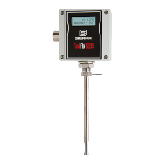
Sierra Series 620S Fast-Flo
™
Insertion Mass Flow Meter
Instruction Manual
Part Number IM-62S
01/99 Revision B
5 Harris Court, Building L Monterey, CA 93940
(831) 373-0200 (800) 866-0200
Fax (831) 373-4402
http://www.sierrainstruments.com
Sierra Instruments b.v. Bolstoen 30A 1046 AV Amsterdam The Netherlands
+31(0)20-6145810 Fax +31(0)20-6145815
IM-62S-B
0-1
Advertisement
Table of Contents

Subscribe to Our Youtube Channel
Related Manuals for Sierra Fast-Flo 620S Series


Summary of Contents for Sierra Fast-Flo 620S Series
- Page 1 Insertion Mass Flow Meter Instruction Manual Part Number IM-62S 01/99 Revision B 5 Harris Court, Building L Monterey, CA 93940 (831) 373-0200 (800) 866-0200 Fax (831) 373-4402 http://www.sierrainstruments.com Sierra Instruments b.v. Bolstoen 30A 1046 AV Amsterdam The Netherlands +31(0)20-6145810 Fax +31(0)20-6145815 IM-62S-B...
- Page 2 Series 620S Instruction Manual Customer Notice Sierra Instruments, Inc. is not liable for any damage or personal injury, whatsoever, resulting from the use of Sierra Instruments standard mass flow meters for oxygen gas. You are responsible for determining if this mass flow meter is appropriate for your oxygen application.
-
Page 3: Table Of Contents
Series 620S Instruction Manual Table of Contents Table of Contents Chapter 1 Introduction Series 620S Mass Flow Meters........1-1 Using this Manual..........1-1 Note and Safety Information........1-2 Receipt of System Components .........1-2 Technical Assistance..........1-2 The Series 620S Flow Sensing Principle......1-3 Smart Electronics Features..........1-4 Enclosure Options .............1-5 Smart Interface Software..........1-5 Chapter 2 Installation and Wiring... - Page 4 Table of Contents Series 620S Instruction Manual Chapter 4 Troubleshooting and Repair Troubleshooting the Flow Meter........4-1 Obtaining a Return Material Authorization......4-3 Appendix A Product Specifications List of Figures 1-1. Series 620S Sensor Assembly ......1-3 2-1. Recommended Pipe Length Requirements....2-2 2-2. Wiring Access..........2-4 2-3.
- Page 5 Series 620S Instruction Manual Table of Contents Warnings and Cautions Warning! All wiring procedures must be performed with the power Off. Warning! To avoid potential electric shock, follow National Electric Code safety practices or your local regulations when wiring this unit to a power source and to peripheral devices. Failure to do so could result in injury or death.
- Page 6 Table of Contents Series 620S Instruction Manual IM-62S-B...
-
Page 7: Chapter 1 Introduction
Chapter 1 Introduction Chapter 1 Introduction Series 620S Fast-Flo™ Mass Flow Meters Sierra’s Series 620S Smart Mass Flow Meter provides a reliable solution for inert gas flow measurement applications. Low-flow sensitivity, fast response and outstanding rangeability have made this model the instrument of choice for many critical gas flow applications. -
Page 8: Note And Safety Information
If the problem persists after following the troubleshooting proce- dures outlined in Chapter 4, contact Sierra Instruments by fax or by E-mail (service@sierrainstruments.com). For phone support you may call (800) 866-0200 or (831) 373-0200 between 8:00 a.m. -
Page 9: The Series 620S Flow Sensing Principle
™ Sierra’s unique Fast-Flo sensor probe is responsible for the unsur- passed accuracy and reliability of Sierra mass flow meters. The sensor consists of two sensing elements–a velocity sensor and a temperature sensor which automatically corrects for changes in gas temperature. -
Page 10: Smart Electronics Features
Chapter 1 Introduction Series 620S Instruction Manual Smart Electronics Features Instrument Validation Two simple tests offer full “field-validation” of your Smart mass flow meter. The first test checks the system electronics, linearization and microprocessor functionality. This is performed by injecting a known input value and confirming that the flow meter outputs the ex- pected value. -
Page 11: Enclosure Options
Smart Interface Software ™ ™ Sierra’s Smart Interface Windows -based software is available for connecting your PC directly to the mass flow meter. An RS-232 serial cable along with floppy disks containing the program and system files are available from the factory. See the Smart Interface User Guide included with the software for operating instructions. - Page 12 Chapter 1 Introduction Series 620S Instruction Manual IM-62S-B...
-
Page 13: Installation Overview
Series 620S Instruction Manual Chapter 2 Installation Chapter 2 Installation Installation Overview The Series 620S flow meter is factory calibrated to the specific pipe size shown on the meter’s Certificate of Calibration. The factory calibration eliminates the task of calculating the average flow across the pipe to determine the correct insertion depth. -
Page 14: Unobstructed Flow Requirements
Chapter 2 Installation Series 620S Instruction Manual Unobstructed Flow Requirements Select an installation site that will minimize possible distortion in the flow profile. Valves, elbows, control valves and other piping com- ponents may cause flow disturbances. Check your specific piping condition against the examples shown below. -
Page 15: Installation
Series 620S Instruction Manual Chapter 2 Installation Installation Use the following data as a guide to prepare the pipe for flow meter insertion. Refer to a standard code for all pipe tapping operations. The following instructions are general in nature and intended for guideline purposes only. -
Page 16: Wiring Connections
Chapter 2 Installation Series 620S Instruction Manual Wiring Connections The NEMA 4X enclosure contains an integral wiring compartment with one dual strip terminal block for power and signal connections and one dual strip terminal block for sensor connections. The en- Warning! closure has one 1/2 inch female NPT conduit entry. -
Page 17: Output Signal Wiring
Series 620S Instruction Manual Chapter 2 Installation Output Signal Wiring All flow meters are equipped with either a calibrated 0-5 VDC (0-10 VDC optional) or a calibrated 4-20 mA output signal. These linear output signals represent 0-100% of the flow meter user full scale. DC Output Wiring The 0-5 VDC (0-10 VDC optional) signal can drive a load of 1000 Ohms. -
Page 18: Load Resistance Versus Input Voltage
Chapter 2 Installation Series 620S Instruction Manual suppl (Volts) (Ohms) 11 (min) 1,125 36 (max) 1,425 Figure 2-5. Load Resistance Versus Input Voltage Current R load 4-20 out (+) 4-20 out (–) – 12 VDC 36 VDC Figure 2-6. Isolated 4-20 mA Current Loop Connections Jumper AUX PWR OUT R load... -
Page 19: Alarm Output Wiring
Series 620S Instruction Manual Chapter 2 Installation Alarm Output Wiring Two alarm outputs (Low Alarm and High Alarm) are included on the flow meter terminal block. The alarm outputs relays are normally-open single-pole relays with one common connection. There are two connection options for alarm outputs–the first with a sepa- rate power supply (isolated) and the second using the flow meter power supply (non-isolated). -
Page 20: Remote Sensor Probe Wiring
Remote Sensor Probe Wiring Use only factory supplied cables when connecting the sensor probe to a remotely mounted flow meter enclosure. The electron- ics, sensors and interconnecting cables supplied by Sierra Instru- Caution! Changing the length of ments are calibrated as a complete precision mass flow circuit. -
Page 21: Range Selection Wiring
Series 620S Instruction Manual Chapter 2 Installation Range Selection Wiring If your meter is equipped with an optional second range calibration, connect a contact switch as shown below. When the switch is closed the device changes to Range 2. Open the switch to return to Range1. Figure 2-12. - Page 22 Chapter 2 Installation Series 620S Instruction Manual 2-10 IM-62S-B...
-
Page 23: Using The Smart Electronics Basic Features
Series 620S Instruction Manual Chapter 3 Operation Chapter 3 Operation Using the Smart Electronics Basic Features Three push buttons allow selection and adjustment of the basic user functions. Use the push buttons to enter: • alarm parameters Caution! • change the user full scale Before making any ad- •... -
Page 24: Using The Single-Digit Led For Programming
Chapter 3 Operation Series 620S Instruction Manual Flow Meter Start Up When applying power to a flow meter equipped with the optional LCD display you will see the product name, the software version, unit serial number, the range number, the user full scale (UFS), the current flow rate and the totalized flow. -
Page 25: Using The Lcd Display For Programming
Series 620S Instruction Manual Chapter 3 Operation Using the LCD Display for Programming Start Up Screens Sierra Flow meter model Flow Meter Software version Version Meter serial number Serial No. Run Mode LCD Display FUNCTIONS Current flow rate Flow Totalized flow... -
Page 26: Entering Alarm Parameters
If you choose not to not be reporting or use the high alarm for a specific alarm function, Sierra recommends measuring gas flow that you set the high alarm at 100% of the user full scale setting during adjustments. -
Page 27: K-Factor Adjustment
Series 620S Instruction Manual Chapter 3 Operation K-Factor Adjustment Entering a K-factor adjusts the meter’s output signal without affect- ing the factory calibration curve. Use the K-factor calibration offset for additional flow profile compensation (the factory includes an ini- Caution! tial flow profile correction in the calibration curve of the unit). -
Page 28: User Full Scale Adjustment
Chapter 3 Operation Series 620S Instruction Manual User Full Scale Adjustment The user full scale (UFS) feature adjusts the flow meter output range anywhere within 50% to 100% of the factory full scale (FFS). This Caution! feature allows you to re-range the voltage or current output of the The flow meter must meter to accommodate different flow rates. -
Page 29: Time Response Delay Adjustment
Series 620S Instruction Manual Chapter 3 Operation Time Response Delay Adjustment Changing the Time Response Delay with the LCD Display 1. Press FUNCTION, enter the password. Press FUNCTION until Time Response appears on the display. 2. Use the UP or DOWN button to adjust the time response delay from 0.10 to 7.2 seconds. - Page 30 Chapter 3 Operation Series 620S Instruction Manual IM-62S-B...
-
Page 31: Using The Smart Electronics Advanced Features
Series 620S Instruction Manual Chapter 3 Operation Using the Smart Electronics Advanced Features Zero and span (Function 1 through 4) can be used to validate system operation and calibrate the digital to analog signals on the Smart electronics device. Additionally, these functions can compensate for Caution! resistance in long signal cables connected to your data collection or Adjusting zero or... -
Page 32: Current Zero Adjustment
Chapter 3 Operation Series 620S Instruction Manual Note: when adjusting zero the current signal will be driven to 4 mA and when adjusting span the current signal will be driven to 20 mA. We recom- mend recording the current values before making any changes to the current zero or span settings. -
Page 33: Instrument Validation
Series 620S Instruction Manual Chapter 3 Operation Instrument Validation System electronics are verified by injecting a known input value and confirming that the flow meter outputs the expected value. This test confirms that the microprocessor, analog to digital and digital to analog converters, the linearizer and the display are working prop- erly. -
Page 34: Electronics Validation Procedure
Chapter 3 Operation Series 620S Instruction Manual Electronics Validation Procedure 1. Verify the flow meter is off line from any remote communica- tions. Make sure the meter’s user full scale setting is the same as the factory full scale setting. If not, adjust the user full scale Caution! value as needed. -
Page 35: Sensor Validation Procedure
Series 620S Instruction Manual Chapter 3 Operation Calibration Certificate Values Validation Test Results Flow Flow Sample Bridge Indicated Output Indicated Meter Output Meter Point Voltage Flow (V or mA) Flow Stated (V or mA) Stated (LCD) Accuracy Accuracy 100% Table 3-1. Electronics Validation Results Sensor Validation Procedure 1. -
Page 36: Sensor Validation Results
Chapter 3 Operation Series 620S Instruction Manual 4. Set the multimeter to read Ohms in the 2K range. Connect the multimeter to terminals J5 and J6 (temperature sensor). Measure the resistance between J5 and J6 and record the temperature sen- sor resistance (in Ohms) in Table 3-2. -
Page 37: Chapter 4 Troubleshooting And Repair
4-3 for Return Material Authorization (RMA) and shipping instructions. Flow Meter Calibration Sierra Instruments maintains fully equipped, quality controlled Flow Calibration Metrology Laboratories for re-calibration. These labo- ratories have ISO 9001 certification. If the flow body or electronics have been damaged or if you simply want to have the flow meter re- calibrated, contact the factory for shipping instructions. - Page 38 No power Turn on power to the flow meter sensor assembly Low flow cutoff too high Correct low flow cutoff programming using Sierra’s Smart Interface software Flow rate below meter’s minimum Contact factory for instructions flow rating Microprocessor locked Switch off power, wait 10 seconds,...
-
Page 39: Obtaining A Return Material Authorization
Before returning any Series 620S Mass Flow Meter to the factory, you must obtain a Return Material Authorization (RMA) form from Sierra Instruments Customer Service. Have your model number and serial number available when you call. Contact Customer Service at: (800) 866-0200 or (831) 373-0200 in the U.S. - Page 40 Chapter 4 Troubleshooting & Repair Series 620S Instruction Manual IM-62S-B...
-
Page 41: Appendix A Product Specifications
Series 620S Instruction Manual Appendix A Specifications Appendix A Product Specifications Operating Specifications Gases Air, nitrogen and other non-combustible, non-corrosive gases Mass Flow Rates 0 to 200 sfpm (0 to 1 nmps) minimum, 0 to 20,000 sfpm (0 to 100 nmps) maximum for air and nitrogen (maximum full scale varies with gas) Dual Calibration User-selectable dual ranges or two different gases (the user full scale for... - Page 42 Appendix A Specifications Series 620S Instruction Manual Mounting Dimensions Length Chart for all Views Code (101.6) (152.4) (228.6) 13.0 (330.2) 18.0 (457.2) 24.0 (609.6) Standard Enclosure - Side View Standard Enclosure - Front View Remote Enclosure - Front View Remote Enclosure - Side View Enclosure-Junction Box - Side View Enclosure-Junction Box - Front View IM-62S-B...
Need help?
Do you have a question about the Fast-Flo 620S Series and is the answer not in the manual?
Questions and answers