Sierra 241 Series Instruction Manual
Vortex volumetric and mass flow meters
Hide thumbs
Also See for 241 Series:
- Instruction manual (63 pages) ,
- Quick install manual (2 pages) ,
- Instruction manual (16 pages)
Table of Contents
Troubleshooting

Related Manuals for Sierra 241 Series


Summary of Contents for Sierra 241 Series
- Page 1 Sierra 240/241Series Instruction Manual Table of Contents 240/241 Series Vortex Volumetric and Mass Flow Meters Models: 240-V, VT, VTP, LP / 241-V, VT, VTP, LP, Cryogenic Instruction Manual Document Number IM-240 Revision: M.8/19 IM-240...
- Page 2 Unless you have specifically ordered Sierra’s optional O cleaning, this flow meter may not be fit for oxygen service. Sierra Instruments, Inc., is not liable for any damage or personal in- jury, whatsoever, resulting from the use of Sierra Instruments standard mass flow meters for oxygen gas.
-
Page 3: Table Of Contents
Sierra 240/241Series Instruction Manual Table of Contents Table of Contents Chapter 1 Introduction InnovaMassVortex Mass Flow Meters ..........1-1 Using this Manual ................. 1-1 Note and Safety Information ............1-2 Receipt of System Components ............ 1-2 Technical Assistance ..............1-2 How the InnovaMass Vortex Meter Operates ........ - Page 4 Table of Contents Sierra 240/241Series Instruction Manual Pulse Output Connections ............2-30 Alarm Output Connections ............2-32 Remote Electronics Wiring ............2-33 Optional Input Electronics Wiring ..........2-34 Optional Energy EMS RTD Input Wiring ........2-34 Optional External 4-20 mA Input Wiring ........2-35 Optional Contact Closure Input Wiring ........
- Page 5 Sierra 240/241Series Instruction Manual Table of Contents First Check Items ................. 5-8 Record Values ..................5-8 Determine the Fault ................5-9 Symptom: Output at no Flow ............5-9 Symptom: Erratic Output .............. 5-9 Symptom: No Output ..............5-11 Symptom: Meter Displays Temperature Fault ......5-12 Symptom: Meter Displays Pressure Fault ........
- Page 6 Table of Contents Sierra 240/241Series Instruction Manual 2-20. Non-Isolated Freq. Out. Using External Power Supply ..2-23 2-21. Backlight Using External Power Supply ......2-23 2-22. Loop Power Volumetric Flowmeter Junction Box ....2-24 2-23. Loop Power Mass Flowmeter Junction Box ......2-25 2-24.
- Page 7 Sierra 240/241Series Instruction Manual Table of Contents Warnings and Cautions Warning! Consult the flow meter nameplate for specific flow meter approvals before any hazardous location installation. Hot tapping must be performed by a trained professional. U.S. regulations often require a hot tap permit.
-
Page 8: Chapter 1 Introduction
MODBUS or HART communications are also available. In- novaMass digital electronics allows for easy reconfiguration for most gases, liquids and steam. The Sierra InnovaMass 240 and 241 vortex meters’ simple installation combines with an easy-to-use interface that provides quick set up, long term reliability and accurate mass flow meas- urement over a wide range of flows, pressures and temperatures. -
Page 9: Note And Safety Information
(800)-866-0200 or (831) 373-0200 between 7:30 a.m. and 5:00 p.m. MST. When calling Technical Support, have the following information on hand: the serial number and Sierra order number (all marked on the meter nameplate) the problem you are encountering and any corrective action taken ... -
Page 10: Velocity Measurement
How the InnovaMass Vortex Mass Flow Meter Operates Figure 1-1. In-Line Vortex Multivariable Mass Flow Meter Sierra’s 240/241 Series multivariable vortex mass flow meters use a unique sensor head to monitor mass flow rate by directly measuring three variables–fluid velocity, temperature and pressure. The built-in flow computer calculates the mass flow rate and volumetric flow rate based on these three direct measurements. -
Page 11: Vortex Shedding Frequency
Chapter 1 Introduction Sierra 240/241 Series Instruction Manual Vortex Shedding Frequency Von Karman vortices form downstream of a shedder bar into two distinct wakes. The vortices of one wake rotate clockwise while those of the oth- er wake rotate counterclockwise. Vortices generate one at a time, alter- nating from the left side to the right side of the shedder bar. -
Page 12: Flow Velocity Range
Sierra 240/241 Series Instruction Manual Chapter 1 Introduction Flow Velocity Range To ensure trouble-free operation, vortex flow meters must be correctly sized so that the flow velocity range through the meter lies within the measurable velocity range (with acceptable pressure drop) and the linear range. -
Page 13: Temperature Measurement
Chapter 1 Introduction Sierra 240/241 Series Instruction Manual As shown in Figure 1-3, InnovaMass meters exhibit a constant Strouhal number across a large range of Reynolds numbers, indicating a con- sistent linear output over a wide range of flows and fluid types. Below... -
Page 14: Flow Meter Configurations
240 Series in-line flow meter (replaces a section of the pipeline) 241 Series insertion flow meter (requires a “cold” tap or a “hot” tap into an existing pipeline) Both the in-line and insertion configurations are similar in that they both use identical electronics and have similar sensor heads. -
Page 15: Line Size / Process Conditions / Materials
Chapter 1 Introduction Sierra 240/241 Series Instruction Manual Line Size / Process Connections / Materials The 240 In-line model is built for line sizes ½ through 4 inch wafer or ½ through 8 inch flanged design using ANSI 150, 300, 600, PN16, 40, or 64 class flanges. -
Page 16: Chapter 2 Installation
Chapter 2 Installation Chapter 2 Installation Installation Overview Sierra’s InnovaMass Vortex Flow Meter installations are simple and straightforward. Both the 240 In-Line and 241 Insertion type flow meter installations are covered in this chapter. After reviewing the installation requirements given below, see page 2-3 for 240 installation instructions. -
Page 17: Unobstructed Flow Requirements
Minimum Required Upstream Downstream Diameters Diameters Example 10 D 15 D 25 D 10 D 10 D 20 D 25 D 10 D D=Internal diameter of channel. N/A=Not applicable Figure 2-1. Recommended Pipe Length Requirements for Installation, 240/241 Series IM-240... -
Page 18: 240 In-Line Flow Meter Installation
Sierra 240/241Series Instruction Manual Chapter 2 Installation 240 In-Line Flow Meter Installation Install the 240 In-Line Flow Meter between two conventional pipe flanges as shown in Figures 2-3 and 2-4. Table 2-1 provides the recommended minimum stud bolt lengths for wafer-style meter body size and different flange ratings. -
Page 19: Wafer-Style Flow Meter Installation
Chapter 2 Installation Sierra 240/241Series Instruction Manual Wafer-Style Flow Meter Installation Install the wafer-style meter between two conventional pipe flanges of the same nominal size as the flow meter. If the process fluid is a liquid, make sure the meter is located where the pipe is always full. This may require locating the meter at a low point in the piping system. -
Page 20: Flange-Style Flow Meter Installation
Sierra 240/241Series Instruction Manual Chapter 2 Installation Place the remaining studs between the pipe flanges. Tighten the nuts in the sequence shown in Figure 2-2. Check for leaks after tightening the flange bolts Flange-Style Flow Meter Installation Install the flange-style meter between two conventional pipe flanges of the same nominal size as the flow meter. -
Page 21: 241 Insertion Flow Meter Installation
Chapter 2 Installation Sierra 240/241Series Instruction Manual 2. Seat the meter level and square on the mating connections with the flange stamped with a flow arrow on the upstream side, with the arrow head pointing in the direction of flow. Position a gasket in place for each side. -
Page 22: Cold Tap Guidelines
Sierra 240/241Series Instruction Manual Chapter 2 Installation Cold Tap Guidelines Refer to a standard code for all pipe tapping operations. The following tapping instructions are general in nature and intended for guideline pur- poses only. 1. Turn off the flow of process gas, liquid or steam. Verify that the line is not pressurized. -
Page 23: Hot Tap Guidelines
Chapter 2 Installation Sierra 240/241Series Instruction Manual Hot Tap Guidelines Refer to a standard code for all pipe tapping operations. The following tapping instructions are general in nature and intended for guideline pur- poses only. Warning! Hot tapping must be 1. -
Page 24: Hot Tap Sequence
Sierra 240/241Series Instruction Manual Chapter 2 Installation Connect isolation valve and test for leaks xxxxxxxxxxxxxxxxxxxx xxxxxxxxxxxxxxxxxxxx Purge pipe xxxxxxxxxxxxxxxxxxxx xxxxxxxxxxxxxxxxxxxx Figure 2-5. Hot Tap Sequence IM-240... -
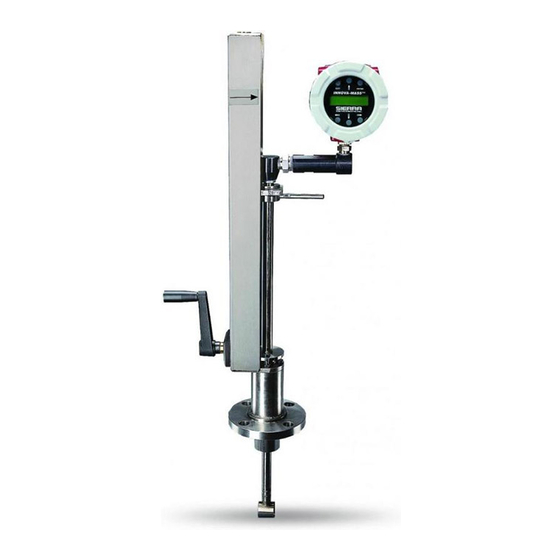
Page 25: Flow Meter Insertion
Chapter 2 Installation Sierra 240/241Series Instruction Manual Flow Meter Insertion The sensor head must be properly positioned in the pipe. For this reason, it is important that insertion length calculations are carefully followed. A sensor probe inserted at the wrong depth in the pipe will result in inaccu- rate readings. -
Page 26: Installing Meters With A Compression Connection
Sierra 240/241Series Instruction Manual Chapter 2 Installation Installing Flow Meters with a Compression Connection* Use the following formula to determine insertion length for flow meters (NPT and flanged) with a compression process connection. The installa- tion procedure is given on the next page. -
Page 27: Flow Meter With Compression Type Fitting
Chapter 2 Installation Sierra 240/241Series Instruction Manual Insertion Procedure for Meters with a Compression Connection Figure 2-7. Flow Meter with Compression Type Fitting 1. Calculate the required sensor probe insertion length. Caution! 2. Fully retract the stem until the sensor head is touching the bottom of The sensor alignment the stem housing. -
Page 28: Installing Meters With A Packing Gland Connection
Sierra 240/241Series Instruction Manual Chapter 2 Installation Installing Flow Meters with a Packing Gland Connection* Use the formula below to determine the insertion depth for flow meters (NPT and flanged) equipped with an insertion tool. To install, see the next page for instructions for meters with a permanent insertion tool. -
Page 29: Flow Meter With Permanent Insertion Tool
Chapter 2 Installation Sierra 240/241Series Instruction Manual Insertion Procedure for Flow Meters with Permanent Insertion Tool Figure 2-9. Flow Meter with Permanent Insertion Tool 1. Calculate the required sensor probe insertion length (see previous page). Measure from the depth marker arrow down the stanchion and scribe a mark at the calculated insertion depth. -
Page 30: Flow Meter With Removable Insertion Tool
Sierra 240/241Series Instruction Manual Chapter 2 Installation Insertion Procedure for Flow Meters with Removable Insertion Tool Figure 2-10. Flow Meter with Removable Insertion Tool 1. Calculate the required sensor probe insertion length. Measure from the depth marker arrow down the stanchion and scribe a mark at the calculated insertion depth. -
Page 31: Insertion Calculation (Meters Without Insertion Tool)
Chapter 2 Installation Sierra 240/241Series Instruction Manual 7. Tighten the packing gland nuts to stop leakage around the stem. Do not torque over 20 ft-lbs. 8. Slide the stem clamp back into position. Torque stem clamp bolts to 15 ft-lbs. Replace the stem clamp nuts and torque to 10-15 ft-lbs. - Page 32 Sierra 240/241Series Instruction Manual Chapter 2 Installation Insertion Procedure for Flow Meters with No Insertion Tool (Packing Gland Connection) 1. Calculate the required sensor probe insertion length. Warning! 2. Fully retract the stem until the sensor head is touching the bottom of the...
-
Page 33: Adjusting Meter Orientation
Chapter 2 Installation Sierra 240/241Series Instruction Manual Adjusting Meter Orientation Depending on installation requirements, you may need to adjust the meter orientation. There are two adjustments available. The first rotates the posi- tion of the LCD display/keypad and is available on both in-line and inser- tion meters. -
Page 34: Enclosure Adjustment
Sierra 240/241Series Instruction Manual Chapter 2 Installation Enclosure Adjustment (240 Series Only) Figure 2-13. Enclosure Viewing Adjustment To avoid damage to the sensor wires, do not rotate the enclosure beyond 180-degrees from the original position. To adjust the enclosure: 1. Remove power to the flow meter. -
Page 35: Loop Power Flow Meter Wiring Connections
Chapter 2 Installation Sierra 240/241Series Instruction Manual Loop Power Flow Meter Wiring Connections The NEMA 4X enclosure contains an integral wiring compartment with one dual strip terminal block (located in the smaller end of the enclosure). Two 3/4-inch Warning! female NPT conduit entries are available for separate power and signal wiring. -
Page 36: 4-20 Ma Output Connections
Sierra 240/241Series Instruction Manual Chapter 2 Installation 4-20 mA Output Connections The InnovaMass meter has a single 4-20 mA loop. The 4-20 mA loop cur- rent is controlled by the meter electronics. The electronics must be wired in series with the sense resistor or current meter. The current control elec- tronics require 12 volts at the input terminals to operate correctly. -
Page 37: Pulse Output Connections
Chapter 2 Installation Sierra 240/241Series Instruction Manual Pulse Output Connections The pulse output is used for a remote counter. When the preset volume or mass (defined in the totalizer settings, see page 3-10) has passed the me- ter, the output provides a 50 millisecond square pulse. -
Page 38: Frequency Output Connections
Sierra 240/241Series Instruction Manual Chapter 2 Installation Frequency Output Connections The frequency output is used for a remote counter. It can be scaled to out- put a 1 to 10 kHz signal proportional to mass or volume flow, tempera- ture, pressure or density. -
Page 39: Remote Electronics Wiring
Chapter 2 Installation Sierra 240/241Series Instruction Manual Remote Electronics Wiring The remote electronics enclosure should be mounted in a convenient, easy to reach location. For hazardous location installations, make sure to ob- serve agency requirements for installation. Allow some slack in the inter- face cable between the junction box and the remote electronics enclosure. -
Page 40: Loop Power Mass Flowmeter Junction Box
Sierra 240/241Series Instruction Manual Chapter 2 Installation TEMPERATURE SHLD 5&6 SHIELD RED 6 BLK 6 BLK 5 RED 5 VORTEX BLK 1 RED 1 BLK 2 SENSOR V RED 2 SENSOR V SHLD 1&2 SHIELD SHLD 3&4 SHIELD BLK 3... -
Page 41: High Power Flow Meter Wiring Connections
Chapter 2 Installation Sierra 240/241Series Instruction Manual High Power Meter Wiring Connections The NEMA 4X enclosure contains an integral wiring compartment with one dual strip terminal block (located in the smaller end of the enclosure). Two Warning! 3/4-inch female NPT conduit entries are available for separate power and To avoid potential electric shock, follow signal wiring. -
Page 42: Dc Power Connections
Sierra 240/241Series Instruction Manual Chapter 2 Installation 100 to 240 VAC @ 5 Watts Max. Chassis screw safety ground must be used for proper operation. Figure 2-25. AC Power Connections OPTION 1 OPTION 2 1 2 3 FREQ PULSE ALARM... -
Page 43: 4-20 Ma Output Connections
Chapter 2 Installation Sierra 240/241Series Instruction Manual 4-20 mA Output Connections The standard InnovaMass Flow Meter has a single 4-20 mA loop. Two additional loops are available on the optional communication board. The 4-20 mA loop current is controlled by the meter electronics. The electron- ics must be wired in series with the sense resistor or current meter. -
Page 44: Frequency Output Connections
Sierra 240/241Series Instruction Manual Chapter 2 Installation mA Meter For HART communications the signal loop must have a DC Power minimum of 250 ohms load DC Common resistance. > 250 Ohm DC powered meters only Figure 2-30. Non-Isolated 4–20 mA Output Using Meter Input Power Supply... -
Page 45: Pulse Output Connections
Chapter 2 Installation Sierra 240/241Series Instruction Manual AC or DC powered meters Freq. Out voltage = +V Freq. Out + Select resistor so that current Freq. Out - through Freq. Out <= 40 mA Figure 2-32. Isolated Frequency Output Using External Power Supply Freq. -
Page 46: Isolated Pulse Output Using External Power Supply
Sierra 240/241Series Instruction Manual Chapter 2 Installation the flow meter power supply is an acceptable driver voltage for the load connected. (Take into account that the current used by the pulse load comes from the meter’s power supply). Use the third configuration if you have an AC powered unit only. -
Page 47: Alarm Output Connections
Chapter 2 Installation Sierra 240/241Series Instruction Manual Alarm Output Connections One alarm output (Alarm 1) is included on the standard InnovaMass flow meter. Two or more alarms (Alarm 2 and Alarm 3) are included on the optional communication board. The alarm output optical relays are nor- mally-open single-pole relays. -
Page 48: Remote Electronics Wiring
Sierra 240/241Series Instruction Manual Chapter 2 Installation + 24VDC Out - 24VDC Out AC units only Meter provided DC Power Figure 2-40. Isolated Alarm Output Using Meter Provided Power Supply Remote Electronics Wiring The remote electronics enclosure should be mounted in a convenient, easy to reach location. -
Page 49: Optional Input Electronics Wiring
Chapter 2 Installation Sierra 240/241Series Instruction Manual Optional Input Electronics Wiring The meter has two optional input wiring terminals. These can be used to input a Remote or Second RTD input in the case of an Energy Monitoring meter, for the input of a Remote Pressure Transducer, to pass a Contact Closure or for a Remote Density measurement to name a few. -
Page 50: Optional External 4-20 Ma Input Wiring
Sierra 240/241Series Instruction Manual Chapter 2 Installation Optional External 4-20 mA Input Wiring The meter is set to have Option 1 used for the external input. Program- ming menus that pertain to the optional 4-20 mA input are located in the Hidden Diagnostics Menu in Chapter 5. -
Page 51: Optional Contact Closure Input Wiring
Chapter 2 Installation Sierra 240/241Series Instruction Manual Option 1 Option 2 AC units only. Meter provided DC power. + 24 VDC OUT - 24 VDC OUT Ext. 4-20 mA Input Device Figure 2-45. External 4-20 mA Input Wiring - AC Powered Meter... -
Page 52: Chapter 3 Operating Instructions
Sierra 240/241 Series Instruction Manual Chapter 3 Operation Chapter 3 Operating Instructions After installing the InnovaMass mass vortex flow meter, you are ready to begin operation. The sections in this chapter explain the display/keypad commands, meter start-up and programming. The meter is ready to operate at start up without any special pro- gramming. -
Page 53: Start Up
Chapter 3 Operation Sierra 240/241 Series Instruction Manual Start-Up To begin flow meter operation: Verify the flow meter is installed and wired as described in Chapter 2. Apply power to the meter. At start up, the unit runs a series of self-... - Page 54 Sierra 240/241 Series Instruction Manual Chapter 3 Operation Run Mode Screens ENTER Mass Flow Password Rate Volume ENTER Flow Rate Press Exit to return Setup to Run Mode Menus Temperature Pressure Energy EMS Energy Meters Only Density Total keys to access...
-
Page 55: Using The Setup Menus
Chapter 3 Operation Sierra 240/241 Series Instruction Manual Using the Setup Menus IM-240... -
Page 56: Programming The Flow Meter
Sierra 240/241 Series Instruction Manual Chapter 3 Operation Programming the Flow Meter 1. Enter the Setup Menu by pressing the ENTER key until prompted for a password. (All outputs are disabled while using the Setup Menus.) 2. Use the keys to select the password characters (1234 is the factory-set password). -
Page 57: Output Menu
Chapter 3 Operation Sierra 240/241 Series Instruction Manual Output Menu ENTER Run Mode Password ENTER Output keys to access menus Menu < Measure > None Mass Volume 4-20 mA Output 1 < 4 mA = xxxx > < 20mA = xxxx >... - Page 58 Sierra 240/241 Series Instruction Manual Chapter 3 Operation Example for Setting an Output The following shows how to set Output 1 to measure mass flow with 4 mA = 0 lb/hr and 20 mA = 100 lb/hr with a time constant of 5 seconds. (All outputs are disabled while using the Setup Menus.) First, set the desired units of measurement: Use ...
-
Page 59: Display Menu
Chapter 3 Operation Sierra 240/241 Series Instruction Manual Display Menu ENTER Run Mode Password ENTER Display keys to access menus Menu Cycle Time (sec) If Cycle Time is set to zero, manual advance is required Number of Digits Used to set the number of digits displayed after the decimal point... -
Page 60: Alarms Menu
Sierra 240/241 Series Instruction Manual Chapter 3 Operation Alarms Menu ENTER Run Mode Password ENTER Alarms * see below keys to access menus Menu <Measure> None Mass <Mode> Volume None Relay Alarm 1 <Measure> units ** Energy More > HIGH Alarm (>) -
Page 61: Totalizer #1 Menu
Chapter 3 Operation Sierra 240/241 Series Instruction Manual Totalizer #1 Menu ENTER Run Mode Password ENTER Totalizer keys to access menus Menu Totaling Example: Inactive Mass Volume Maximum flow rate = 600 gallons per minute Energy (600 gallons per minute = 10 gallons per second) -
Page 62: Totalizer #2 Menu
Sierra 240/241 Series Instruction Manual Chapter 3 Operation Totalizer #2 Menu ENTER Run Mode Password ENTER Totalizer keys to access menus Menu Totaling Inactive Mass Volume Energy Reset Total ? YES or NO Use the Totalizer #2 to Monitor Flow or Energy. Note that Totalizer #2 does not operate a relay, it is for monitoring only. -
Page 63: Energy Menu
Chapter 3 Operation Sierra 240/241 Series Instruction Manual Energy Menu – For EMS Energy Meters Only ENTER Run Mode Password ENTER Energy Menu keys to access menus Loc in Sent Flow Yes or No Heating System Yes or No % Returned... -
Page 64: Fluid Menu
Sierra 240/241 Series Instruction Manual Chapter 3 Operation Fluid Menu ENTER Run Mode Password ENTER Fluid keys to access menus Menu < Liquid Water Ammonia Chlorine Flowing Fluid Liquids > < Density > < AL > < BL Other Liquids >... - Page 65 Chapter 3 Operation Sierra 240/241 Series Instruction Manual Mole Weight = lb /(lb ·mol), CRIT PRESS = psia, CRIT TEMP = °R, Density = Kg/m Viscosity = cP (centipoise). 3-14 IM-240...
-
Page 66: Units Menu
Sierra 240/241 Series Instruction Manual Chapter 3 Operation Units Menu ENTER Run Mode Password ENTER Units keys to access menus Menu Mass Flow Unit Ston = Short Ton = 2000 lb lb, Ston, Lton, gram Lton = Long Ton = 2240 lb... -
Page 67: Time And Date Menu
Chapter 3 Operation Sierra 240/241 Series Instruction Manual Time & Date Menu ENTER Run Mode Password ENTER Time & Date Menu keys to access menus Set Time xx:xx:xx Set Date xx/xx/xx Use the Time and Date Menu to enter the correct time and date into the flow meter’s memory. -
Page 68: Diagnostics Menu
Sierra 240/241 Series Instruction Manual Chapter 3 Operation Diagnostics Menu ENTER Run Mode Password ENTER Diagnositcs Menu keys to access menus Simulate Vortex Sim Vor Freq Frequency (Hz) * Simulate Temperature Sim Temp 1, 2 For a V model in any fluid, enter nominal operating temperature and... -
Page 69: Calibration Menu
Chapter 3 Operation Sierra 240/241 Series Instruction Manual If the meter display indicates a temperature or pressure fault, a substitute value can be entered to allow flow calculations to continue at a fixed value until the source of the fault is identified and corrected. -
Page 70: Password Menu
Sierra 240/241 Series Instruction Manual Chapter 3 Operation Password Menu ENTER Run Mode Password ENTER Password Menu keys to access menus Set Password 1234 Use the Password Menu to set or change the system password. The factory-set password is 1234. -
Page 71: Chapter 4 Serial Communications
Sierra 240/241 Series Instruction Manual Chapter 4 Serial Communications Chapter 4 Serial Communications HART Communications The HART Communications Protocol (Highway Addressable Remote Transducer Protocol) is a bidirectional digital serial communications protocol. The HART signal is based on the Bell 202 standard and is superimposed on 4-20 mA Output 1. Point-to- point (analog / digital) and multi-drop (digital only) modes are supported. - Page 72 Chapter 4 Serial Communications Sierra 240/241 Instruction Manual DC Powered Meter Wiring Vortex Meter RS485 RS485 RS485 GND R load, Current Power 250 ohm Meter Supply minimum Field Connection Remote Connection for Communicator for Communicator Figure 4-2.DC Powered Meter Wiring (HART)
- Page 73 Sierra 240/241 Series Instruction Manual Chapter 4 Serial Communications Multi-Point Meter Wiring Figure 1 Multi-point (digital only) loop power model shown To activate Multi-drop mode, put a device ID of 1 to 15 in the “Dev id” menu. ( 0 is point to point mode ) This fixed the 4-20 ma. output to 4 ma.
-
Page 74: Hart Commands With The Dd Menu
Chapter 4 Serial Communications Sierra 240/241 Instruction Manual HART Commands with the DD Menu Online Menu 1 Device Setup 1 Display Unit 1 Mass flo unit 2 Vol unit 3 Temp unit 4 Energy flo unit 5 Line press unit... - Page 75 Sierra 240/241 Series Instruction Manual Chapter 4 Serial Communications HART Commands with the DD Menu Continued Analog Output Menu 1 Fix Analog Output 2 Trim Analog Output From Online Menu 1 PV is 3 Configure AO1 2 PV AO1 Out...
- Page 76 Chapter 4 Serial Communications Sierra 240/241 Instruction Manual HART Commands with the DD Menu Continued Fluid Menu From Online Menu 1 Fluid Liquid Water 2 Fluid Type Other Liquid Ammonia Goyal-Dorais Chlorine API-2540 Nat Gas AGA8 Real Gas Other Liquid Density...
- Page 77 Sierra 240/241 Series Instruction Manual Chapter 4 Serial Communications HART Commands with the DD Menu Continued Diagnostics Menu 1 Vortex Diag 1 Vtx Freq From Online Menu 2 Press Diag 2 Sim Vtx Freq 3 Temp Diag 3 Vtx AtoD...
- Page 78 Chapter 4 Serial Communications Sierra 240/241 Instruction Manual HART Commands with the DD Menu Continued Sensor Cal Menu To Calibration Review Menu 1 Calibration Review From Online Menu 1 Vol snsr unit 1 Vtx Freq 2 Vortex Sensor 2 USL...
-
Page 79: Hart Commands With Generic Dd Menu
Sierra 240/241 Series Instruction Manual Chapter 4 Serial Communications HART Commands with Generic DD Menu Online Menu 1 Device Setup 1 Process Variables 1 Snsr 1 4 mA 2 PV 2 AI % Rnge 2 20 mA 3 PV AO... - Page 80 Chapter 4 Serial Communications Sierra 240/241 Instruction Manual Fast Key Sequence Use password 16363. Sequence Description Access Notes 1,1,1 Snsr View Primary variable value 1,1,2 AI % Rnge View Analog output % range 1,1,3 View Analog output, mA 1,2,1 Test Device...
- Page 81 Sierra 240/241 Series Instruction Manual Chapter 4 Serial Communications Sequence Description Access Notes 1,4,3,1,3,1 4 mA View Loop test, fix analog output at 4 mA 1,4,3,1,3,2 20 mA View Loop test, fix analog output at 20 mA 1,4,3,1,3,3 Other Edit...
-
Page 82: Modbus Communications
This document describes the preliminary implementation of the Modbus communication protocol for use in monitoring common process variables in the Sierra InnovaMass 240 and 241 mass vortex flow meters. The physical layer utilizes the half-duplex RS-485 port, and the Modbus protocol. - Page 83 Sierra 240/241 Series Instruction Manual Chapter 4 Serial Communications Pin Labeling (among devices) “RS-485 –” = “A” = “TxD-/RxD-” = “Inverting pin” “RS-485 +” = “B” = “TxD+/RxD+” = “Non-Inverting pin” “RS-485 GND” = “GND” = “G” = “SC” = “Reference”...
-
Page 84: Menu Items
Chapter 4 Serial Communications Sierra 240/241 Instruction Manual Menu Items The following menu items are in the display, DD option Output Menu and allow selection and control of the Modbus communication protocol. Address When the Modbus protocol is selected, the Modbus address is equal to the user programmable device address if it is in the range 1…247, in accordance with the Modbus specification. - Page 85 Sierra 240/241 Series Instruction Manual Chapter 4 Serial Communications The following four selections are available in this menu; when selecting an item, the protocol is changed immediately without having to press the Enter key. 0-1:2-3 Most significant register first, most significant byte first (default)
-
Page 86: Register Definitions
Chapter 4 Serial Communications Sierra 240/241 Instruction Manual Each range of register numbers maps to a unique range of addresses that are determined by the function code and the register number. The address is equal to the least significant four digits of the register number minus one, as shown in the following table. - Page 87 Sierra 240/241 Series Instruction Manual Chapter 4 Serial Communications Registers Variable Data Type Units Function Addresses Code 65100-65101 Serial number unsigned long — 03, 04 30525-30526 Totalizer unsigned long display units* 03, 04 524-525 32037-32042 Totalizer units string — 03, 04...
- Page 88 Chapter 4 Serial Communications Sierra 240/241 Instruction Manual reading a single 16-bit register, then the value will likely be invalid. The floating point registers with values in display units are scaled to the same units as are displayed, but are instantaneous values that are not smoothed. If...
- Page 89 Sierra 240/241 Series Instruction Manual Chapter 4 Serial Communications Control Register Definitions The only writeable registers in this implementation are the Reset Exception Status, Reset Meter and Reset Totalizer functions, which are implemented as ”coils” which may be written with the Write Single Coil command (function code 05) to address 8 through 10, respectively, (register #00009 through #00011).
- Page 90 Chapter 4 Serial Communications Sierra 240/241 Instruction Manual Exception Response Message Format Examples Read the exception status byte from the device with address 1: 01 07 41 E2 01 Device address 07 Function code, 04 = read exception status A typical response from the device is as follows:...
- Page 91 Sierra 240/241 Series Instruction Manual Chapter 4 Serial Communications An attempt to read register(s) that don’t exist 01 04 00 00 00 50 F1 D2 01 Device address 04 Function code 4 = read input register 00 00 Starting address...
- Page 92 Chapter 4 Serial Communications Sierra 240/241 Instruction Manual The unit responds with an identical message to that transmitted, and the totalizer is reset. If the “coil” is turned off as in the following message, the response is also identical to the transmitted message, but the totalizer is not affected.
-
Page 93: Bacnet Mstp Description
Sierra 240/241 Series Instruction Manual Chapter 4 Serial Communications BACnet MS/TP Description This document describes the function and operation of the optional BACnet interface for the Sierra Instruments 240/241Series. BACnet MS/TP Description BACnet Master-Slave/Token-Passing (MSTP) driver implements a data link protocol that uses the services of the RS- 485 physical layer. -
Page 94: Supported Bacnet Objects
11. Change the required settings and press Exit then the Enter button to save the configuration. 12. Reboot the vortex meter by powering off and on Note: a) The 240/241 Series supports 9600, 19200, and 38,400 baud rates. b) MAC address range is 0-127 Supported BACnet Objects A BACnet object represents physical or virtual equipment information, as a digital input or parameters. - Page 95 Sierra 240/241 Series Instruction Manual Chapter 4 Serial Communications Protocol_Version Protocol_Revision Protocol_Services_Supported Protocol_Object_Types_Supported Object_List Max_ADPU_Length_Accepted Segmentation_Supported ADPU_Timeout Number_Of_ADPU_Retries Max_Masters Max_Info_Frames Device_Address_Binding Database_Revision Status_Flags Event_State ...
- Page 96 Chapter 4 Serial Communications Sierra 240/241 Instruction Manual Object-List {(analog-input,1),(analog-input,2),(analog-input,3),(analog-input,4), (analog- input,5), (analog-input,6),(analog-input,7),(analog-input,8) (analog-input,9),(analog- input,10), (analog-input,11), (analog-input,12), (analog-input,13),(analog- input,14), (analog-input,15),(analog-input,16),(analog-input,17), (analog- input,18),(analog-input,19),(binary-input,1),(binary-input,2),(binary-input,3),(binary- input,4), (binary-value,1), (device,7) } Max-Apdu-Length-Accepted Segmentation-Supported no-segmentation Apdu-Timeout 3000 Number-Of-APDU-Retries Max-Master Max-Info-Frames Device-Address-Binding Database-Revision Note - Device Communication Control: Password – “vortek”...
- Page 97 Sierra 240/241 Series Instruction Manual Chapter 4 Serial Communications Pressure pounds-force-per-square-inch, This AI Object measures the inches-of-water, Pressure of the fluid. inches-of-mercury, millimeters-of-mercury, bars, millibars, pascals, kilopascals This AI Object measures the Density kilograms-per-cubic-meter Density of the fluid. Energy Flow...
- Page 98 Chapter 4 Serial Communications Sierra 240/241 Instruction Manual Channel 3 milliamperes This Object indicates the value of the 3rd analog output. (4-20mA) Scaled Freq hertz This Object indicates the value of the scaled frequency output. Flow Velocity feet-per-second This Object indicates the fluid velocity.
- Page 99 Sierra 240/241 Series Instruction Manual Chapter 4 Serial Communications Binary Input Object: Vortex Mass Flow Meters Binary Input type objects are described in the below Table. Object Object Description Instance Name Alarm1 The status of the three alarms may be monitored via the Modbus command.
-
Page 100: Annex - Bacnet Protocol Implementation Conformance
Chapter 4 Serial Communications Sierra 240/241 Instruction Manual ANNEX – BACnet Protocol Implementation Conformance Statement Date: 19-April-2012 Applications Software Version: 1.07 Firmware Revision: N/A BACnet Protocol Revision: 4 BACnet Standardized Device Profile (Annex L): BACnet Operator Workstation (B-OWS) BACnet Advanced Operator Workstation (B-AWS) ... - Page 101 Sierra 240/241 Series Instruction Manual Chapter 4 Serial Communications Services Supported Read Property Execute Write Property Execute Read Property Multiple Execute Write Property Multiple Execute Who-Is Execute I-Am Initiate Who-Has Execute I-Have Initiate Device Communication Control Execute Segmentation Capability: Able to transmit segmented messages Window Size Able to receive segmented messages...
- Page 102 Chapter 4 Serial Communications Sierra 240/241 Instruction Manual Standard Object Types Supported: Standard Object Types Supported Dynamically Dynamically Additional Range Object Type Creatable Delete-able Writable Properties Restrictions Analog Input (AI) None None Binary Input (BV) None None Binary Value None...
- Page 103 Sierra 240/241 Series Instruction Manual Chapter 4 Serial Communications Object List: Properties of Analog Input/Value Objects Type Present Status Event Out of Name Units Value Flags State Service Volume Flow F,F,F,F Normal False Mass Flow F,F,F,F Normal False Temperature 1...
- Page 104 Chapter 4 Serial Communications Sierra 240/241 Instruction Manual Data Link Layer Options: BACnet IP, (Annex J) BACnet IP, (Annex J), Foreign Device ISO 8802-3, Ethernet (Clause 7) ANSI/ATA 878.1, 2.5 Mb. ARCNET (Clause 8) ANSI/ATA 878.1, EIA-485 ARCNET (Clause 8), baud rate(s) MS/TP master (Clause 9), baud rate(s): 9600, 19200, 38400...
- Page 105 Sierra 240/241 Series Instruction Manual Chapter 4 Serial Communications Character Sets Supported: Indicating support for multiple character sets does not imply that they can all be supported simultaneously. ANSI X3.4 IBM™/Microsoft™DBCS ISO 8859-1 ISO 10646 (UCS-2) ISO 10646 (UCS-4) JIS C 6226...
-
Page 106: Acronyms And Definitions
Chapter 4 Serial Communications Sierra 240/241 Instruction Manual Acronyms and Definitions Item Description APDU Application Protocol Data Unit BACnet Building Automation and Control Network- Data communication protocol MS/TP Master-Slave Token passing(a twisted pair RS485 network created by BACnet) BIBB BACnet Interoperability Building Block (Specific individual function blocks for data exchange between interoperable devices). -
Page 107: Chapter 5 Troubleshooting And Repair
Sierra 240/241 Series Instruction Manual Chapter 5 Troubleshooting & Repair Chapter 5 Troubleshooting and Repair Warning! Hidden Diagnostics Menus Before attempting any flow meter repair, verify that the The menus shown on the following page can be accessed using the password line is not pressurized. - Page 108 Chapter 5 Troubleshooting & Repair Sierra 240/241 Series Instruction Manual Hidden Diagnostics Menus { ------------ Level One Values ------------ } { ------------------------------ Level Two Values ------------------------------ } 4-20(1), Zero Output Type Alarm(1) Test xxxx None 4-20(1), Fscale Alarm(2) Test Pulse Out Queue...
-
Page 109: Level One Hidden Diagnostics Values
Sierra 240/241 Series Instruction Manual Chapter 5 Troubleshooting & Repair Level One Hidden Diagnostics Values f = Vortex shedding frequency (Hz). fi = Adaptive filter – should be approximately 25% higher than the vortex shedding frequency, this is a low-pass filter. If the meter is using the Filter Control (see below) in the manual mode, fi will be displayed as fm. -
Page 110: Level Two Hidden Diagnostics Values
Chapter 5 Troubleshooting & Repair Sierra 240/241 Series Instruction Manual Lvl = Threshold level. If the Low Flow Cutoff in the calibration menu is set above this value, the meter will read zero flow. The Lvl level can be checked at no flow. At no flow, the Lvl must be below the Low Flow Cutoff setting or the meter will have an output at no flow. - Page 111 Sierra 240/241 Series Instruction Manual Chapter 5 Troubleshooting & Repair 4-20(2) FScale = Analog counts to cal. full scale on analog output 2. 4-20(3) Zero = Analog counts to calibrate zero on analog output 3. 4-20(3) FScale = Analog counts to cal. full scale on analog output 3.
- Page 112 Chapter 5 Troubleshooting & Repair Sierra 240/241 Series Instruction Manual Factory Defaults = Reset factory defaults. If you change this to Yes and press Enter, all the factory configuration is lost and you must reconfigure the entire program. Consult the factory before performing this process, it is required only in very rare cases.
-
Page 113: Analog Output Calibration
Sierra 240/241 Series Instruction Manual Chapter 5 Troubleshooting & Repair Init Displ. (sec) = Enter a value in seconds to initialize the display every xxx seconds. Enter a value of 0 to disable initializing the display. Analog Output Calibration To check the 4–20 mA circuit, connect a DVM in series with the... -
Page 114: Troubleshooting The Flow Meter
Chapter 5 Troubleshooting & Repair Sierra 240/241 Series Instruction Manual Troubleshooting the Flow Meter Warning! Before attempting any flow meter repair, verify that the line is not pressurized. Always remove main power before disassembling any part of the mass flow meter. Use hazardous area precautions if applicable. Static sensitive electronics - use electro-static discharge precautions. -
Page 115: Determine The Fault
Sierra 240/241 Series Instruction Manual Chapter 5 Troubleshooting & Repair Record values - Hidden Diagnostics Menu continued: With No Flow With Flow (if possible) Pe(V) = Pv(V) = Ck = Lvl = Adj. Filter = Iso. Power Volts = Sig. Rev = Record the following values from the Calibration Menu. - Page 116 Chapter 5 Troubleshooting & Repair Sierra 240/241 Series Instruction Manual 3. The meter may be reacting to actual changes in the flow stream. The output can be smoothed using a time constant. The displayed values can be smoothed using the time constant in the Display Menu.
-
Page 117: Symptom: No Output
Sierra 240/241 Series Instruction Manual Chapter 5 Troubleshooting & Repair PRESSURE VORTEX TEMPERATURE Figure 5-1.Electronics Stack Sensor Connections VORTEX PRESSURE TEMPERATURE Figure 5-2.Remote Feed Through Board Sensor Connections Symptom: No Output 1. For remote mounted electronics, carefully check all the wiring connections in the remote mount junction box. -
Page 118: Symptom: Meter Displays Temperature Fault
Chapter 5 Troubleshooting & Repair Sierra 240/241 Series Instruction Manual OUTSIDE INSIDE OUTSIDE Figure 5-3.Vortex Sensor Connector With the sensor still disconnected, go to the first level of the hidden diagnostics and display the vortex shedding frequency, f. Hold a finger on the three exposed pins on the analog board. -
Page 119: Symptom: Meter Displays Pressure Fault
Sierra 240/241 Series Instruction Manual Chapter 5 Troubleshooting & Repair OUTSIDE OUTSIDE Figure 5-4.Temperature Sensor Connector 4. Consult factory with findings Symptom: Meter Displays Pressure Fault 1. For remote mounted electronics, carefully check all the wiring connections in the remote mount junction box. There are 18 connections that must be correct, verify each color (black and red), shield, and wire number. -
Page 120: Electronics Assembly Replacement
Chapter 5 Troubleshooting & Repair Sierra 240/241 Series Instruction Manual Electronics Assembly Replacement (All Meters) The electronics boards are electrostatically sensitive. Wear a grounding wrist strap and make sure to observe proper handling precautions required for static-sensitive components. 1. Turn off power to the unit. -
Page 121: Pressure Sensor Replacement (Series 240 Only)
Returning Equipment to the Factory Factory Calibration—All Models Sierra Instruments maintains a fully-equipped calibration laboratory. All measuring and test equipment used in the calibration of Sierra transducers are traceable to NIST Standards. Sierra is ISO-9001 registered and conforms to the requirements of ANSI/NCSL-Z540 and ISO/IEC Guide 25. -
Page 122: Harris Court, Building L Monterey, Ca
Pack your instrument carefully. Use the original packaging and foam or bubble wrap (packing peanuts NOT recommended) and include a copy of the RMA form (complete with Sierra supplied RMA number) with the unit(s). Ship the unit(s) to the following address: Sierra Instruments, Inc. -
Page 123: Appendix A Product Specifications
Sierra 240/241 Series Instruction Manual Appendix A Specifications Appendix A Product Specifications IM-240... - Page 124 Appendix A Specifications Sierra 240/241 Series Instruction Manual IM-240...
- Page 125 Sierra 240/241 Series Instruction Manual Appendix A Specifications IM-240...
- Page 126 Appendix A Specifications Sierra 240/241 Series Instruction Manual IM-240...
- Page 127 Sierra 240/241 Series Instruction Manual Appendix A Specifications IM-240...
- Page 128 Appendix A Specifications Sierra 240/241 Series Instruction Manual IM-240...
- Page 129 Sierra 240/241 Series Instruction Manual Appendix A Specifications IM-240...
- Page 130 Appendix A Specifications Sierra 240/241 Series Instruction Manual IM-240...
- Page 131 Sierra 240/241 Series Instruction Manual Appendix A Specifications IM-240...
- Page 132 Appendix A Specifications Sierra 240/241 Series Instruction Manual A-10 IM-240...
- Page 133 Sierra 240/241 Series Instruction Manual Appendix A Specifications IM-240 A-11...
- Page 134 Appendix A Specifications Sierra 240/241 Series Instruction Manual A-12 IM-240...
- Page 135 Sierra 240/241 Series Instruction Manual Appendix A Specifications IM-240 A-13...
-
Page 136: Appendix B Approvals
Sierra 240/241 Series Instruction Manual Appendix B Approvals Appendix B Approvals FM / FMC Approval Class I, Division 1, Groups B, C, & D, Class II/III, Division 1, Groups E, F, & G Type 4X and IP66, T6 Ta = -40 to 60°C... - Page 137 Appendix B Approvals Sierra 240/241 Series Instruction Manual Declaration of Conformity Sierra Instruments, Inc. 5 Harris Court, Building L Monterey, CA 93940 Declares in sole responsibility that the product: Vortex Flow Meter Type 240 / 241 Conforms with the regulations of the European Directives:...
-
Page 138: Appendix C Flow Meter Calculations
Sierra 240/241 Series Instruction Manual Appendix C Flow Meter Calculations Appendix C Flow Meter Calculations In-Line Flow Meter Calculations Volume Flow Rate Mass Flow Rate Q Flowing Velocity Where: A = Cross sectional area of the pipe (ft^2) - Page 139 Appendix C Flow Meter Calculations Sierra 240/241 Series Instruction Manual Insertion Flow Meter Calculations Flowing Velocity V Volume Flow Rate Mass Flow Rate Where: A = Cross sectional area of the pipe (ft^2) f = Vortex shedding frequency (pulses / sec)
- Page 140 Sierra 240/241 Series Instruction Manual Appendix C Flow Meter Calculations Fluid Calculations Calculations for Steam T & P When “Steam T & P” is selected in the “Real Gas” selection of the Fluid Menu, the calculations are based on the equations below.
- Page 141 Appendix C Flow Meter Calculations Sierra 240/241 Series Instruction Manual Calculations for Gas (“Real Gas” and “Other Gas”) Use this formula to determine the settings for “Real Gas; Gas” selections and “Other Gas” selections entered in the Fluid Menu. The calculations for gas were taken from Richard W.
- Page 142 Sierra 240/241 Series Instruction Manual Appendix C Flow Meter Calculations Calculations for Liquid Use this formula to determine the settings for “Goyal-Dorais” selections and “Other Liquid” selections entered in the Fluid Menu. The liquid cal- culations were taken from Richard W. Miller, Flow Measurement Engi- neering Handbook (Third Edition, 1996).
-
Page 143: Appendix D Glossary
Sierra 240/241 Series Instruction Manual Appendix B Glossary Appendix D Glossary A B C D Cross sectional area. ACFM Actual Cubic Feet Per Minute (volumetric flow rate). ASME American Society of Mechanical Engineers. Bluff Body A non-streamlined body placed into a flow stream to create vortices. - Page 144 Appendix B Glossary Sierra 240/241 Series Instruction Manual I J K L In-Line Flow Meter A flow meter which includes a short section of piping which is put in-line with the user’s piping. Insertion Flow Meter A flow meter which is inserted into a hole in the us- er’s pipeline.
- Page 145 Sierra 240/241 Series Instruction Manual Appendix B Glossary Liquid vapor pressure at flowing conditions (psia or bar absolute). Q R S T Flow rate, usually volumetric. Rangeability Highest measurable flow rate divided by the lowest measurable flow rate. Reynolds Number...
-
Page 146: Appendix E Warranty Policy
Appendix E Warranty Policy LIMITED WARRANTY POLICY- REGISTER ONLINE All Sierra products are warranted to be free from defects in material and workmanship and will be repaired or replaced at no charge to Buyer, provided return or rejection of product is made within a reasonable period but no longer than one (1) year for calibration and non-calibration defects, from date of delivery.
Need help?
Do you have a question about the 241 Series and is the answer not in the manual?
Questions and answers