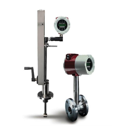
Sierra InnovaMass 240 Series Instruction Manual
Multivariable mass vortex flow meters
Hide thumbs
Also See for InnovaMass 240 Series:
- Instruction manual (20 pages) ,
- Quick install manual (2 pages) ,
- Instruction manual (16 pages)
Table of Contents
Advertisement
Quick Links
Download this manual
See also:
Instruction Manual
Advertisement
Table of Contents

Subscribe to Our Youtube Channel
Related Manuals for Sierra InnovaMass 240 Series


Summary of Contents for Sierra InnovaMass 240 Series
- Page 1 240/241 Series Modbus Instruction Manual Modbus Device Specification for Models: 240-V, -VT, -VTP, -LP & 241-V, -VT, -VTP, -LP Multivariable Mass Vortex Flow Meters Part Number: IM240/241 Modbus, Rev. V1 May 2013...
- Page 2 IMPORTANT CUSTOMER NOTICE- OXYGEN SERVICE Sierra Instruments, Inc. is not liable for any damage or personal injury, whatsoever, resulting from the use of Sierra Instruments standard mass flow meters for oxygen gas. You are responsible for determining if this mass flow meter is appropriate for your oxygen application.
- Page 3 Warnings and Cautions Warning! Agency approval for hazardous location installations varies between flow meter models. Consult the flow meter nameplate for specific flow meter approvals before any hazardous location installation. Warning! Hot tapping must be performed by a trained professional. U.S. regulations often require a hot tap permit. The manufacturer of the hot tap equipment and/or the contractor performing the hot tap is responsible for providing proof of such a permit.
- Page 4 Receipt of System Components When receiving a Sierra mass flow meter, carefully check the outside packing carton for damage incurred in shipment. If the carton is damaged, notify the local carrier and submit a report to the factory or distributor.
-
Page 5: Table Of Contents
Table of Contents Table of Contents ........................…….5 Chapter 1: Modbus Communications… ..................6 Applicable Flow Meter Models ........................... 6 Wiring..................................6 Pin Labeling (among devices)............................ 7 Menu Items ................................7 Address..................................7 Comm Protocol ................................7 Modbus Units ................................8 Modbus Order ................................ -
Page 6: Chapter 1: Modbus Communications
Chapter 1: Modbus Communications Applicable Flow Meter Models Sierra’s InnovaMass® 240 and 241 Mass Vortex Flow Meters with Modbus communication protocol and firmware version 4.00.58 and above. Overview This document describes the implementation of the Modbus communication protocol for use in monitoring common process variables in the Sierra InnovaMass Vortex flow meter. -
Page 7: Pin Labeling (Among Devices)
Pin Labeling (among devices) “RS-485 –” = “A” = “TxD-/RxD-” = “Inverting pin” “RS-485 +” = “B” = “TxD+/RxD+” = “Non-Inverting pin” “RS-485 GND” = “GND” = “G” = “SC” = “Reference” OPTION 1 OPTION 2 1 2 3 240/241 Pins Rs485 Labeling Synonyms RS485 -... -
Page 8: Modbus Units
protocol, the change is made as soon as the Enter key is pressed. Modbus Units The Modbus Units menu is to control what units, where applicable, the meter’s variables will be displayed in. Internal – these are the base units of the meter, °F, psia, lbm/sec , ft /sec, Btu/sec , lbm/ft Display –... -
Page 9: Register Definitions
30001–39999 Read-only 16 bit registers ("input 03 (read holding registers) 04 (read registers"), IEEE 754 floating point input registers) register pairs, arbitrary length strings encoded as two ASCII characters per 16- bit register 40001–49999 Read/write 16-bit registers ("holding 03 (read holding registers) 06 (write registers"), IEEE 754 floating point single register) 16 (write multiple register pairs, arbitrary length strings... - Page 10 Registers Variable Data Type Units Function Addresses Code 65100-65101 Serial number unsigned long — 03, 04 30525-30526 Totalizer unsigned long display units* 03, 04 524-525 32037-32042 Totalizer units string — 03, 04 2036-2041 30009-30010 Mass flow float display units* 03, 04 30007-30008 Volume flow float...
-
Page 11: Exception Status Definitions
Display TC item in the Display Menu), then the register values will not agree exactly with the displayed values. Exception Status Definitions The Read Exception Status command (function code 07) returns the exception status byte, which is defined as follows. This byte may be cleared by setting “coil” register #00003 (function code 5, address 2, data = 0xff00). Bit(s) Definition Byte order (see Modbus Order on page 2) -
Page 12: Command Message Format
If the first byte of a message is not equal to the unit’s Modbus address, if the unit detects a parity error in any character in the received message (with even or odd parity enabled), or if the message CRC is incorrect, the unit will not respond. - Page 13 A typical response from the device is as follows: *note these are the older register definitions 01 04 18 00 00 03 E8 00 00 7A 02 6C 62 00 00 41 BA 87 F2 3E BF FC 6F 42 12 EC 8B 4D D1 01 Device address 04 Function code 18 Number of data bytes = 24...
- Page 14 01 Device address 05 Function code 5 = write single coil 00 09 Coil address = 9 FF 00 Data to reset totalizer 8C 3A CRC (not the correct CRC EJS-02-06-07) The unit responds with an identical message to that transmitted, and the totalizer is reset. If the “coil” is turned off as in the following message, the response is also identical to the transmitted message, but the totalizer is not affected.
Need help?
Do you have a question about the InnovaMass 240 Series and is the answer not in the manual?
Questions and answers