Table of Contents
Advertisement
Quick Links
Series 780S Instruction Manual
Table of Contents
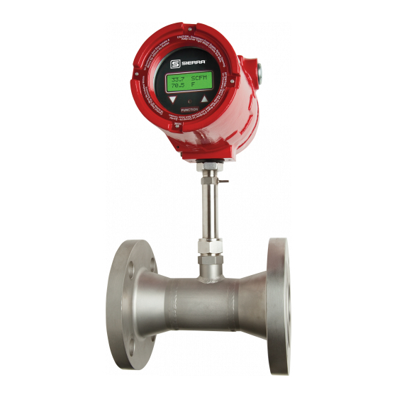
Sierra 780S Series Flat-Trak
™
Mass Flow Meter
Instruction Manual
Part Number IM-78S
07/99 Revision B
5 Harris Court, Building L Monterey, CA 93940
(831) 373-0200 (800) 866-0200
Fax (831) 373-4402
http://www.sierrainstruments.com
Sierra Instruments b.v. Bolstoen 30A 1046 AV Amsterdam The Netherlands
+31(0)20-6145810 Fax +31(0)20-6145815
IM-78S-B
0-1
Advertisement
Table of Contents

Subscribe to Our Youtube Channel
Related Manuals for Sierra 780S Series Flat-Trak


Summary of Contents for Sierra 780S Series Flat-Trak
- Page 1 Mass Flow Meter Instruction Manual Part Number IM-78S 07/99 Revision B 5 Harris Court, Building L Monterey, CA 93940 (831) 373-0200 (800) 866-0200 Fax (831) 373-4402 http://www.sierrainstruments.com Sierra Instruments b.v. Bolstoen 30A 1046 AV Amsterdam The Netherlands +31(0)20-6145810 Fax +31(0)20-6145815 IM-78S-B...
- Page 2 Series 780S Instruction Manual Customer Notice Sierra Instruments, Inc. is not liable for any damage or personal injury, whatsoever, resulting from the use of Sierra Instruments standard mass flow meters for oxygen gas. You are responsible for determining if this mass flow meter is appropriate for your oxygen application.
-
Page 3: Table Of Contents
Series 780S Instruction Manual Table of Contents Table of Contents Chapter 1 Introduction Series 780S Flat-Trak Mass Flow Meters ......1-1 Using this Manual..........1-1 Note and Safety Information........1-2 Receipt of System Components .........1-2 Technical Assistance..........1-2 The Series 780S Flow Sensing Principle......1-3 Smart Electronics Features..........1-4 Enclosure Options .............1-5 ™... - Page 4 Table of Contents Series 780S Instruction Manual Chapter 4 Troubleshooting and Repair Troubleshooting the Flow Meter........4-1 Returning Equipment to the Factory.........4-3 Appendix A Product Specifications List of Figures 1-1. Series 780S Flow Sensing Principle .......1-3 2-1. Flow Meter Orientation........2-2 2-2. Wiring Access NEMA 4X Enclosures .....2-4 2-3.
-
Page 5: Warnings And Cautions
Series 780S Instruction Manual Table of Contents Warnings and Cautions Warning! Agency approval for hazardous location installations varies between flow meter models. Consult the flow meter nameplate for specific flow meter approvals be- fore any hazardous location installation. Warning! All wiring procedures must be performed with the power off. Warning! To avoid potential electric shock, follow National Electric Code safety practices or your local code when wiring this unit to a power source and to peripheral devices. - Page 6 Table of Contents Series 780S Instruction Manual IM-78S-B...
-
Page 7: Chapter 1 Introduction
Series 780S Flat-Trak Mass Flow Meters ™ Sierra’s Series 780S Flat-Trak Mass Flow Meter provides a reliable solution for monitoring gas mass flow rate. Low-flow sensitivity, fast response and outstanding rangeability have made this model the instrument of choice for many critical gas flow applications. The... -
Page 8: Note And Safety Information
If the problem persists after following the troubleshooting procedures outlined in Chapter 4, contact Sierra Instruments by fax or by E-mail (see inside front cover). For urgent phone support you may call (800) 866-0200 or (831) 373-0200 between 8:00 a.m. and 5:00 p.m. PST. -
Page 9: The Series 780S Flow Sensing Principle
™ Sierra’s unique Steel-Trak sensor probe is responsible for the un- surpassed accuracy, ruggedness and reliability of Sierra industrial flow meters. The immersible Steel-Trak sensor consists of two sensing elements–a velocity sensor and a temperature sensor that automatically corrects for changes in gas temperature. -
Page 10: Smart Electronics Features
Chapter 1 Introduction Series 780S Instruction Manual Smart Electronics Features Instrument Validation Two simple tests offer full “field-validation” of your Smart mass flow meter. The first test checks the system electronics, linearization and microprocessor functionality and is performed by injecting a known input value and confirming that the flow meter outputs the expected value. -
Page 11: Enclosure Options
Smart Interface Software ™ ™ Sierra’s Smart Interface Windows -based software is available for connecting your PC directly to the mass flow meter. An RS-232 se- rial cable along with floppy disks containing the program and sys- tem files are available from the factory. See the Smart Interface User Guide included with the software package for operating instructions. - Page 12 Chapter 1 Introduction Series 780S Instruction Manual IM-78S-B...
-
Page 13: Installation Overview
Series 780S Instruction Manual Chapter 2 Installation Chapter 2 Installation Installation Overview ™ The Series 780S Flat-Trak is available with ANSI or DIN flanges, NPT or butt-weld connections. For ease of installation, the meter is Warning! pre-assembled with the sensor probe installed in the flow body. Agency approval for hazardous location installations varies between flow meter models. -
Page 14: Unobstructed Flow Requirements
(1) Number of diameters (D) of straight pipe required between upstream disturbance and the flow meter sensor. Table 2-1. Pipe Length Requirements for Installation Installing the Flow Meter Enclosure SIERRA adjustable to any viewing position Flow direction indicator should point downstream... -
Page 15: Changing Display Orientation
Series 780S Instruction Manual Chapter 2 Installation To install the flow meter: 1. Turn off the flow of process gas. Verify that the line is not pres- surized. Confirm that the installation site meets the minimum up- Caution! stream pipe diameter requirements shown in Table 2-1. When using toxic or cor- rosive gases, purge the line with inert gas for a... -
Page 16: Wiring Connections
Chapter 2 Installation Series 780S Instruction Manual Wiring Connections For NEMA 4X enclosures, use TB2 for power and signal connec- tions, TB1 is for sensor connections. (The terminal designations are labeled inside the enclosure cover.) Warning! To avoid potential electric shock, follow National Elec- Wiring connections NEMA 4X enclosure... -
Page 17: Input Power Wiring
Series 780S Instruction Manual Chapter 2 Installation Input Power Wiring AC Power Wiring The AC power wire size must be 26 to 16 AWG with the wire Warning! stripped 1/4 inch (6 mm). Connect 100 to 240 VAC (300 mA load, All wiring procedures must maximum) to the Neutral and Line terminals on the small, two- be performed with the power... -
Page 18: Dc Input Power Connections (Hazardous-Area)
Chapter 2 Installation Series 780S Instruction Manual DC Power Wiring The DC power wire size must be 26 to 16 AWG with the wire stripped 1/4 inch (6 mm). Connect 18 to 30 VDC (625 mA load, Warning! maximum) to the terminals marked PWR+ and PWR– on the terminal All wiring procedures block. -
Page 19: Output Signal Wiring
Series 780S Instruction Manual Chapter 2 Installation Output Signal Wiring Output signal cable should be completely screened with a 100% shield. You must use metal cable glands that provide cable screen clamping. The cable screen should be connected to the gland and shielded at both ends over 360 degrees. -
Page 20: Load Resistance Versus Input Voltage
Chapter 2 Installation Series 780S Instruction Manual 4-20 mA Output Wiring The 4-20 mA current loop output can be self-powered (non-isolated) or externally powered (isolated). To use the 4-20 mA isolated output, an external 12 to 36 VDC power supply is required. The maximum loop resistance (load) for both types of current loop outputs are de- pendent upon the supply voltage and are given in Figure 2-10. - Page 21 Series 780S Instruction Manual Chapter 2 Installation NEMA 4X Enclosures Current R load 4-20 out (+) 4-20 out (–) – 12 VDC 36 VDC Figure 2-11. Isolated 4-20 mA Current Loop Connections NEMA 4X Enclosures Jumper AUX PWR OUT Current R load 4-20 out (+) V out (–)
-
Page 22: Alarm Output Wiring
Chapter 2 Installation Series 780S Instruction Manual Alarm Output Wiring Two alarm outputs (Low Alarm and High Alarm) are included on the flow meter terminal block. The alarm outputs use optical relays that are normally-open single-pole relays with one common connection. There are two connection options for alarm outputs–the first with a sepa- rate power supply (isolated) and the second using the flow meter power supply (non-isolated). -
Page 23: Remote Sensor Probe Wiring
When connecting the sensor probe to a remotely mounted flow meter enclosure, use only factory supplied cables. The electronics, Caution! sensors and interconnecting cables supplied by Sierra Instruments Changing the length of ca- are calibrated as a complete precision mass flow circuit. - Page 24 Chapter 2 Installation Series 780S Instruction Manual NEMA 4X Enclosures Remote Sensor enclosure probe GREEN Temperature Velocity sensor sensor ORANGE WHITE BLACK Note: Sensor wire color may vary - see label in cover Figure 2-19. Remote Electronics Enclosure to Sensor Connections Figure 2-20.
-
Page 25: Range Selection Wiring
Series 780S Instruction Manual Chapter 2 Installation Figure 2-22. Sensor Junction Box to Remote Enclosure Connections Range Selection Wiring To access range selection, connect two wires on the terminal strip as shown below. When the switch is closed the device changes to Range 2. - Page 26 Chapter 2 Installation Series 780S Instruction Manual 2-14 IM-78S-B...
-
Page 27: Flow Meter Start Up
Series 780S Instruction Manual Chapter 3 Operation Chapter 3 Operation This chapter covers flow meter operation, programming and instru- ment validation procedures. All instructions include directions for using either the optional LCD display or the internal Smart electron- ics device for programming. If your meter is not equipped with the optional display, you will need a good quality digital voltmeter or multimeter for programming and validation procedures. -
Page 28: Using The Smart Electronics Basic Features
Chapter 3 Operation Series 780S Instruction Manual Using the Smart Electronics Basic Features This section covers the basic features of the Smart electronics and in- cludes instructions on: entering alarm parameters Caution! Before making any ad- changing the user full scale justment to the Smart adjusting the K-factor electronics device, verify... -
Page 29: Lcd Display Programming Menu
Series 780S Instruction Manual Chapter 3 Operation LCD Display Programming Menu Start Up Screens Sierra Flow meter model Flow Meter Software version Version Meter serial number Serial No. Run Mode LCD Display FUNCTIONS Current flow rate Flow Totalized flow Total Flow... -
Page 30: Single-Digit Led Programming Menu
Chapter 3 Operation Series 780S Instruction Manual Single-Digit LED Programming Menu Run Mode FUNCTION Software version Assignments Version shown in series of 3 digits Voltage Zero Press Range Range in use FUNCTION Voltage Span Press FUNCTION to view or Current Zero change settings. -
Page 31: Entering Alarm Parameters
If you choose not to use reporting or measuring gas the high alarm for a specific alarm function, Sierra recommends that flow during adjustments. you set the high alarm at 100% of the user full scale setting which creates an “over-range”... -
Page 32: K-Factor Adjustment
Chapter 3 Operation Series 780S Instruction Manual K-Factor Adjustment Entering a K-factor adjusts the meter’s output signal without affect- ing the factory calibration curve. Use the K-factor calibration offset for additional flow profile compensation (the factory includes an ini- tial flow profile correction in the calibration curve of the unit). Caution! Entering a K-factor using the LCD Display The flow meter must not be... -
Page 33: User Full Scale Adjustment
Series 780S Instruction Manual Chapter 3 Operation User Full Scale Adjustment The user full scale (UFS) feature adjusts the flow meter output range anywhere within 50% to 100% of the factory full scale (FFS). This feature allows you to re-range the voltage or current output of the Caution! The flow meter must not be meter to accommodate different flow rates. -
Page 34: Time Response Delay Adjustment
Chapter 3 Operation Series 780S Instruction Manual Time Response Delay Adjustment Changing the Time Response Delay using the LCD Display 1. Select FUNCTION, enter the password. Select FUNCTION again until Time Response appears on the display. 2. Use UP or DOWN to adjust the time response delay from 0.10 to 7.2 seconds. -
Page 35: Totalizer Reset
Series 780S Instruction Manual Chapter 3 Operation Totalizer Reset If your device is equipped with the optional LCD display, reset the totalizer using the magnetic switches or device buttons. If you are unable to open the flow meter enclosure, use a magnet to reset the totalizer as shown below. - Page 36 Chapter 3 Operation Series 780S Instruction Manual 3-10 IM-78S-B...
-
Page 37: Using The Smart Electronics Advanced Features
Series 780S Instruction Manual Chapter 3 Operation Using the Smart Electronics Advanced Features Zero and span (Function 1 through 4) can be used to validate system operation and calibrate the digital to analog signals on the Smart Caution! electronics device. Additionally, these functions can compensate for Adjusting zero or span will resistance in long signal cables connected to your data collection or affect meter calibration. -
Page 38: Current Zero Adjustment
Chapter 3 Operation Series 780S Instruction Manual Note: when adjusting zero the current signal will be driven to 4 mA and when adjusting span the current signal will be driven to 20 mA. We recom- mend recording the current values before making any changes to the current zero or span settings. -
Page 39: Instrument Validation
Series 780S Instruction Manual Chapter 3 Operation Instrument Validation System electronics are verified by injecting a known input value and confirming that the flow meter outputs the expected value. This test confirms that the microprocessor, analog to digital and digital to analog converters, the linearizer and the display are working prop- erly. -
Page 40: Electronics Validation Procedure
Chapter 3 Operation Series 780S Instruction Manual Electronics Validation Procedure 1. Verify the flow meter is off line from any remote communica- tions. Make sure the meter’s user full scale setting is the same as the factory full scale setting. If not, adjust the user full scale Caution! value as needed. -
Page 41: Sensor Validation Procedure
Series 780S Instruction Manual Chapter 3 Operation Calibration Certificate Values Validation Test Results Flow Flow Sample Bridge Indicated Output Indicated Meter Output Meter Point Voltage Flow (V or mA) Flow Stated (V or mA) Stated (LCD) Accuracy Accuracy 100% Table 3-1. Electronics Validation Results Sensor Validation Procedure 1. -
Page 42: Sensor Validation Results
Chapter 3 Operation Series 780S Instruction Manual 4. Set the multimeter to read Ohms in the 2K range. Connect the multimeter to the terminals of J5 and J6 (temperature sensor). Measure the resistance between J5 and J6 and record the tem- perature sensor resistance (in Ohms) in Table 3-2. -
Page 43: Chapter 4 Troubleshooting And Repair
Flow Meter Calibration Sierra Instruments maintains a fully-equipped calibration laboratory. All measuring and test equipment used in the calibration of Sierra meters are traceable to NIST standards. Sierra is ISO-9001 regis- tered and conforms to the requirements of ANSI/NCSL-Z540 and ISO/IEC Guide 25. - Page 44 Chapter 4 Troubleshooting & Repair Series 780S Instruction Manual Problem Possible Cause Solution Velocity measurement is Very erratic or non-uniform flow Follow installation requirements shown erratic or fluctuating in Chapter 2 Moisture present in gas flow Install a water trap or filter upstream of the flow meter sensor Flow conditioning plates are not Correct flow meter orientation...
-
Page 45: Returning Equipment To The Factory
Returning Equipment to Factory Before returning any mass flow meter to the factory, you must re- quest and complete a Sierra Calibration/Repair Data Sheet. To obtain the data sheet contact Customer Service at: (800) 866-0200 or (831) 373-0200 in the US or +31(0)20-6145810 in Europe. - Page 46 Chapter 4 Troubleshooting & Repair Series 780S Instruction Manual IM-78S-B...
-
Page 47: Appendix A Product Specifications
Series 780S Instruction Manual Appendix A Specifications Appendix A Product Specifications Performance Specifications Accuracy ± 2% of reading from 10 to 100% of calibrated range ± 0.5% of full scale below 10% of calibrated range Repeatability ± 0.2% of full scale Temperature Coefficient ±... - Page 48 Appendix A Specifications Series 780S Instruction Manual –4 Leak Integrity 1 X 10 atm cc/sec of helium maximum Power Requirements 18 to 30 VDC (regulated), 625 mA maximum 100 to 240 VAC , 50/60 Hz, 15 watts maximum* not available on NEMA 4X enclosures Output Signal Linear 0-5 VDC or 0-10 VDC proportional to mass flow rate, 1000 Ohms mini- mum load resistance, or Linear 4-20 mA proportional to mass flow rate, 700...
Need help?
Do you have a question about the 780S Series Flat-Trak and is the answer not in the manual?
Questions and answers