Sierra QuadraTherm 640i Instruction Manual
Profibus dp device specification for thermal mass flow meters
Hide thumbs
Also See for QuadraTherm 640i:
- Instruction manual (132 pages) ,
- Quick start manual (4 pages) ,
- Instruction manual (26 pages)
Table of Contents
Advertisement
Quick Links
See also:
Instruction Manual
Advertisement
Table of Contents

Related Manuals for Sierra QuadraTherm 640i


Summary of Contents for Sierra QuadraTherm 640i
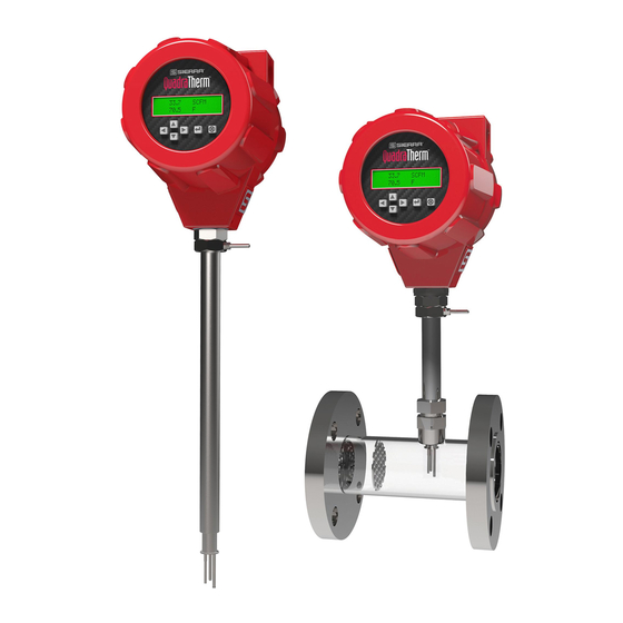
- Page 1 QuadraTherm 640i & 780i ® Profibus DP Instruction Manual Profibus DP Device Specification for Models: 640i and 780i Thermal Mass Flow Meters Part Number: IM-640i/780i-DP, Rev. V1 June 2014 Part Number: IM600/700 Profibus DPDP Rev.V1 May 2013...
- Page 2 IMPORTANT CUSTOMER NOTICE- OXYGEN SERVICE Sierra Instruments, Inc. is not liable for any damage or personal injury, whatsoever, resulting from the use of Sierra Instruments standard mass flow meters for oxygen gas. You are responsible for determining if this mass flow meter is appropriate for your oxygen application.
- Page 3 Warnings and Cautions Warning! Agency approval for hazardous location installations varies between flow meter models. Consult the flow meter nameplate for specific flow meter approvals before any hazardous location installation. Warning! Hot tapping must be performed by a trained professional. U.S. regulations often require a hot tap permit. The manufacturer of the hot tap equipment and/or the contractor performing the hot tap is responsible for providing proof of such a permit.
- Page 4 For urgent phone support you may call (800) 866-0200 or (831) 373-0200 between 8:00 a.m. and 5:00 p.m. PST. In Europe, contact Sierra Instruments Europe at +31 72 5071400. In the Asia-Pacific region, contact Sierra Instruments Asia at +86-21-58798521.
-
Page 5: Table Of Contents
Table of Contents Chapter 1: Introduction ..........................6 Set Up Step Plan ............................6 Chapter 2: Field Bus Installation........................7 Wiring ................................7 Cable ................................8 Termination ..............................8 Status LEDs ..............................9 Chapter 3: Configuration ..........................11 GSD File ..............................11 Cyclic Data Overview (inputs)........................ -
Page 6: Chapter 1: Introduction
Chapter 1: Introduction This manual will explain how to add a Sierra flow meter to a Profibus DP network. Profibus DP allows access to all relevant data available in the flow meter. This manual does not cover the operation of the QuadraTherm 640i/780i. See the... -
Page 7: Chapter 2: Field Bus Installation
Chapter 2: Field Bus Installation Wiring Option DP1 This option uses a full five-wire Profibus DP connection using the M12 connector per the Profibus DP standard. This connection allows you to use ready-made cables, tees, and terminators which maintain a daisy chain topology. -
Page 8: Cable
Option DP2 For applications where the Profibus DP cable needs to be protected in conduit, we offer an alternate terminal block Profibus DP connection. This must be requested at the time of ordering. The PB-5V and PB-GND will not be available to power a terminator. The last device on the Profibus DP segment may need an external “powered terminator”... -
Page 9: Status Leds
Figure 4: Powered Terminator Ready-made terminators are available for easy installation. Status LEDs The interface has two multi-color LED’s mounted inside the enclosure to indicate the status. To access the LED’s, remove the display side cap. Network Status Status LED Status Description Flashing Green/red... - Page 10 Dip Switch The dip switches are located to the left of the LEDs. 1 2 4 8 16 32 64 128 The dip switch is binary encoded with the LSB (least significant bit) on the left side. The switch is only read during power-up.
-
Page 11: Chapter 3: Configuration
Profibus DP system. The GSD-file is a text file containing: Identification info: o Model name: “QuadraTherm 640i/780i” o Vendor name: “Sierra Instruments Inc.” o File name SIER0E14 o Identification number: 0x014E o Bitmap device: “640i_de”... -
Page 12: Dpv0 Cyclic Data Reads (Inputs)
Incoming Cyclic Data (Slave to Master Module 3) Data Description Size (bytes) Format Address Totalizer 32 INT Alarm Status 8 INT Module 4, Module 1+2 Module 5, Module 2+3 Module 6, Module 1+2+3 DPV0 Cyclic Data Reads (inputs) Flow Data type: 32 bit real (same as 32 bit floating point or IEEE 754) Description: The actual flow as measured by the instrument in the active flow units on the 640i/780i. - Page 13 Slot 2 Meter Tune: This 32 bit real number will adjust the flow calibration of the active gas. The factory calibration should be already correct. However this can be used to correct an undetermined application issue. Example 1.100 would increase the flow readings by 10%. Slot 3 Change Active Gas: This is a 16 bit integer data type.
- Page 14 Slot 14 Reads the Last Factory Calibration Date: This 10-character ASCII string has the most recent factory calibration date. Example: 10/10/2010 Slot 15: Reads T1 Wattage: This is an 8-character ASCII string with the reference T1 wattage done at ambient conditions during calibration.
- Page 15 2. The main window is loaded. Go to the file menu and select “Copy GSD.” 3. Locate the SIER0E14.gsd GSD file and load it. The GSD file is added to the Sycon library but it isn’t available yet. Quit the program and restart it to make it available. Configuring a Slave Create a New Configuration and Insert a Master 1.
- Page 16 2. Leave the station address set to zero. Press the “Add” button and then the “OK” button. 3. A window pops up showing the driver linked to the selected master. Press “Yes” to use the hardware. Note: The board ID number changes when extra PCI cards are added to the PC.
- Page 17 Add Slave Here 2. Set the slave filter to “Sierra Instruments Inc.” Select the desired GSD file, press the “Add” button, set the slave address and description to match the slave and press the “OK” button.
- Page 18 3. Double click on the added slave in the main window. The slave configuration window appears. 4. Select the desired module (one only) by double clicking on the module name. Note that you have a choice between module 1, 2, 3, 4, 5, and 6. In the above example, module 6 is chosen for all cyclic data.
- Page 19 Press “Yes” to continue. The data is downloaded to the master: After the download, you can double click the new slave again and see the actual data addresses assigned to your network under the “I Addr.” column. The QuadraTherm is now configured. Click “OK” to close this window. You can now save this configuration file in a convenient location to be used later.
- Page 20 Check The Configuration To confirm the configuration worked, you can start the debug mode. If everything is working correctly then the line between the master and the slave will be green and the bit map shows a green check.
- Page 21 To see the diagnostic status, double click on the slave. Press the “OK” button and leave the debug mode (Online -> Stop Debug Mode). If the line turns red (error found), double click the slave to find out what the problem is.
- Page 22 The diagnostic window gives an indication of a problem, “Station Non Existent” wrong address here: In this case the slave is deactivated. Check the address of “Slave1” to see if it matches with the physical address of the hardware slave. Correct any error found.
- Page 23 2. A window titled “New Channel- Identification” will appear. Type in the new channel name in the “Channel name” field then click “Next.” 3. Choose a master. Below we are using a Hilscher CIF50 master. After choosing a master, click “Next.”...
- Page 24 5. Chose the board and type then click “Next.” 6. You’ll need to import the setup 640i_test.pb file that we created earlier in Syscon. You may browse to the location where you saved it. Click on the Browse button.
- Page 25 7. Browse to the 640i_test.pb you just created in Sycon. Once highlighted, click “Open.” 8. You should see the warning shown below. Click “OK” to synchronize. 9. You can review the summary of the new channel you just created.
- Page 26 10. You may now add your first slave device. Click on “Click to add a device.” 11. Give your new device a name.
- Page 27 12. Set the device ID. Note: ID# 0 was already used for the master, so chose #2. The next two screens will be fine at the default settings. Click “Next.” 13. In the “New Device – Device Type” window choose the “Profibu DP Slave” type. Click “Next.”...
- Page 28 14. To review the new device summary, click “Next.” 15. You have now created a new salve device for your network. Click “Finish.” Adding Tags to Cyclic Data You will now need to create tags to access each piece of cyclic data. Click on “Click to add a static tag”...
- Page 29 The example above is for the Flow. Module 6 was configured so tags for Temperature (IOD4S Float), Pressure (IOD8S Float), Total (IOD12S Float), Total (IOD16S Dword), and Alarm Status (IOB20S) may also be added. Click Ok when done ProfiCore Ultra Diagnostic Kit For a DPV1 data example, we will be using the popular ProfiCore Ultra diagnostic kit.
- Page 30 If you cycle the power on a slave, it will also display it’s name. You can also click on the highlighted square and it will display more information about it to the left. 3. Click on the ProfiCaptain tab. For this test, you won’t need to add the 640i/780i slave to the network sheet.
-
Page 31: Gsd File (Sieroe14.Gsd)
You can use this method to read or write to any DPV1 acyclic Slots. GSD File (SIEROE14.gsd) Below is a printed copy of the SIER0E14.gsd file #Profibus DP_DP ; Sierra Instruments Inc. ; Version 1.0 ; This GSD-File is intended for the Smart Trak mass flow meter ; This Unit support DPV0, DPV1 ;... - Page 32 | ASCII ; 14 | 10 | ASCII ; 15 | System Response | 10 | ASCII ;... GSD_Revision Vendor_Name = "Sierra Instruments Inc." Model_Name = "640i Quadratherm" Revision = "V1.0" Ident_Number = 0x0E14 Protocol_Ident Station_Type FMS_supp Hardware_Release = "V1.2"...
- Page 33 MaxTsdr_19.2 = 60 MaxTsdr_45.45 = 60 MaxTsdr_93.75 = 60 MaxTsdr_187.5 = 60 MaxTsdr_500 = 100 MaxTsdr_1.5M = 150 MaxTsdr_3M = 250 MaxTsdr_6M = 450 MaxTsdr_12M = 800 Redundancy Repeater_Ctrl_Sig = 0 24V_Pins Implementation_Type = "VPC3+C" Bitmap_Device = "640i_De" Bitmap_Diag = "640i_Di" Bitmap_SF = "640i_Sf"...
- Page 34 Prm_Text_Ref=1 EndExtUserPrmData Ext_User_Prm_Data_Const(0) = 0x00,0x00,0x00 Ext_User_Prm_Data_Ref(0) = 1 ; <Module-Definition-List> Module = "Modul 1, 4 bytes in" 0x93 EndModule Module = "Modul 2, 3 x 4 bytes in" 0x93,0x93,0x93 EndModule Module = "Modul 3, 4B 1B in" 0x93,0x90 EndModule Module = "Modul 4, M1 + M2"...
Need help?
Do you have a question about the QuadraTherm 640i and is the answer not in the manual?
Questions and answers