Sierra Top-Trak 820 Series Instruction Manual
Mass flow meters
Hide thumbs
Also See for Top-Trak 820 Series:
- Quick installation instructions (2 pages) ,
- Instruction manual (45 pages)

Related Manuals for Sierra Top-Trak 820 Series


Summary of Contents for Sierra Top-Trak 820 Series
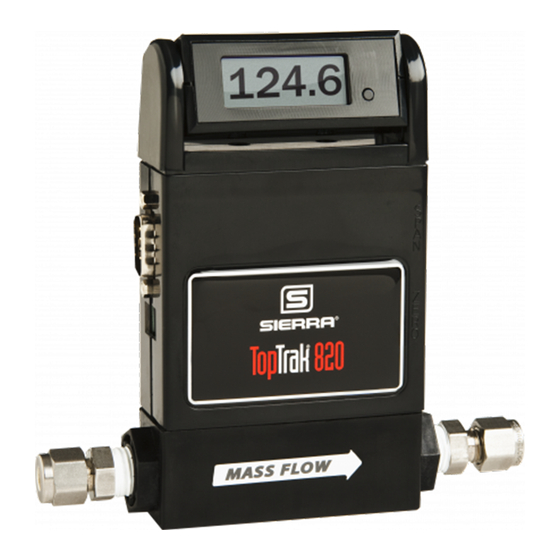
- Page 1 Sierra 820 Series Top-Trak™ Mass Flow Meters Models: 820, 820S, 822, 822S, 824, 824S, 826 and 827 Instruction Manual Part Number IM-82 Revision H, November 2017...
- Page 2 Sierra Instruments, Inc. is not liable for any damage or personal injury, whatsoever, resulting from the use of Sierra Instruments standard mass flow meters or controllers for oxygen gas. You are re- sponsible for determining if this mass flow meter or controller is appropriate for your oxygen appli- cation.
-
Page 3: Table Of Contents
Series 820 Instruction Manual Table of Contents Table of Contents Chapter 1 Introduction Introduction ................. 1-1 Using this Manual .............. 1-1 Safety Information ............. 1-2 Receipt of System Components ........1-2 Technical Assistance ............1-2 Top Trak Features ..............1-3 The 820 Series Flow Sensing Principle ........ - Page 4 Table of Contents Series 820 Instruction Manual Appendix A Conversion Formulas and Gas Tables Appendix B 822/824 Product Specifications Appendix C 822S/824S Product Specifications Appendix D 826/827 Product Specifications List of Figures 1-1. Top-Trak Features (Typical) ........1-2. Flow Paths through the Transducer ......1-3.
- Page 5 Series 820 Instruction Manual Table of Contents Cautions Caution! Only qualified personnel should install the transducer. Caution! Do not supply +DC power at the D-connector while using a power supply at the power jack. Both supplies may be damaged. Caution! Operating a 12 VDC transducer at 24 VDC will cause equip- ment damage.
-
Page 7: Chapter 1 Introduction
Gas tables and conversion formulas are found in Appendix A. The product specifications and dimensional drawings are found in Appendix B. Throughout this manual, we use the word transducer as a ge- neric term to represent all models of Sierra’s 820 Series Top- Trak Mass Flow Meters. IM-82... -
Page 8: Safety Information
Troubleshooting, for specific information and recommendations. If the problem persists after following the troubleshooting proce- dures outlined in Chapter 4, contact Sierra Instruments by fax or by E-mail (see inside front cover). For urgent phone support you may call (800) 866-0200 or (831) 373-0200 between 8:00 a.m. and 5:00 p.m. -
Page 9: Top Trak Features
Series 820 Instruction Manual Chapter 1 Introduction Top-Trak Features Standard Top-Trak Mass Flow Meters require a 12 to 15 VDC ex- ternal power source (24 VDC input power optional). The transduc- er’s 0 to 5 VDC output signal allows for flow recording, data-logging or control. -
Page 10: The 820 Series Flow Sensing Principle
Chapter 1 Introduction Series 820 Instruction Manual The 820 Series Flow Sensing Principle The operating principle of Top-Trak transducers is based on heat transfer and the first law of thermodynamics. During operation process gas enters the instrument’s flow body and divides into two flow paths, one through the sensor tube, the other through the la- minar flow element bypass. -
Page 11: Chapter 2 Installation
Series 820 Instruction Manual Chapter 2 Installation Chapter 2 Installation Installation Overview To ensure a successful installation, inlet and outlet tubing should be clean and free from burrs or rims caused by cutting prior to plumbing the transduc- er into the system. The protective caps covering the inlet/outlet fittings should not be removed until immediately prior to installation. -
Page 12: Installing The Transducer
Chapter 2 Installation Series 820 Instruction Manual Installing the Transducer Follow the installation instructions that apply to your transducer’s process connection. For all 1/2-inch size process connections, observe Caution! the piping recommendations given on page 2-3. Before operation, all Only qualified personnel plumbing should be checked carefully for leaks and the transducer should install the purged with dry nitrogen. - Page 13 Series 820 Instruction Manual Chapter 2 Installation 1/4 inch Female NPT Connections (standard on nylon flow bodies 1. Position the transducer with the flow direction arrow pointing in the di- rection of flow. 2. Use a good quality paste pipe thread sealant. Apply to pipe threads. 3.
-
Page 14: Wiring The Transducer
Chapter 2 Installation Series 820 Instruction Manual Wiring the Transducer Standard Top-Trak transducers require a 12 to 15 VDC power supply (15 VDC nominal, 100 mA maximum). 24 VDC input power is optional. Transducers are connected to the power supply through Caution! either the dedicated DC power jack or through the 9-pin D-connector Do not supply +DC power... - Page 15 Series 820 Instruction Manual Chapter 2 Installation Figure 2-2. Transducer D-Connector Pin Assignments Note: The power jack requires a plug that has a 2.5mm inner diameter and a 5mm outer diameter. The center is positive (+). IM-82...
-
Page 16: Standard 0-5 Vdc Output Signal Wiring
Chapter 2 Installation Series 820 Instruction Manual Standard 0-5 VDC Output Signal Wiring The standard 0-5 VDC output signal flows from Pin 3 (0-5 VDC Out) through the load (1K Ohm minimum) to Pin 7 (Power Common). The figure below is a typical example of input power and output signal connections. -
Page 17: Remote Display Installation
Series 820 Instruction Manual Chapter 2 Installation Figure 2-5. Multiple Transducer Current Loop Connections Remote Display Installation Mount the remote display at a convenient location within reach of the supplied interface cable. The maximum cable length is 100 feet (30 m). Figure 2-6. -
Page 19: Chapter 3 Operation
Series 820 Instruction Manual Chapter 3 Operation Chapter 3 Operation The output signal of the transducer is either 0-5 VDC (standard) or 4-20 mA (optional). The output signal is linear and proportional to the gas mass flow rate. For example, for a 0-5 VDC output signal, 5.00 VDC is the output signal for the full scale listed on the trans- ducer’s nameplate, 2.50 VDC is for one-half of full scale, and 0.00 VDC is for zero flow. -
Page 20: Referencing The Transducer To Non-Standard Conditions
Chapter 3 Operation Series 820 Instruction Manual Referencing the Transducer to Non-Standard Conditions The gas flow rate output of your transducer is referenced to “normal” conditions of 21 °C (70°F) and 760 mm of mercury (1 atmosphere) unless otherwise specified on the certificate of calibration. -
Page 21: Zero And Span Adjustments
Series 820 Instruction Manual Chapter 3 Operation Zero and Span Adjustments The zero and span potentiometers are accessed through the ports marked on the side of the transducer. Normally, span adjustments are not made unless you are calibrating the transducer. The span adjustment should not be used unless you have a known, precise non- zero flow rate that you wish to match. - Page 22 Chapter 3 Operation Series 820 Instruction Manual 820 Totalizer Operation The optional 820 totalizer is designed to provide a totalizer func- tion within the digital display of the 820 series. It will display the flow rate, the total flow or both at once. If your instrument has this option, it is described below.
-
Page 23: Chapter 4 Maintenance And Repair
Calibration of Sierra Instruments flow meters and controllers re- quires a calibrating standard of at least equal accuracy and prefera- bly an order of magnitude better than the transducer, and a skilled factory technician familiar with the Top-Trak. -
Page 24: Flow Path Cleaning Model 822/824
Chapter 4 Maintenance and Repair Series 820 Instruction Manual Flow Path Cleaning Model 822/824 Figure 4-1. Model 822/824 Flow Components Inlet and Outlet Screens 1. Remove the transducer from the system. 2. Remove inlet and outlet fittings. Caution! When using toxic or cor- 3. -
Page 25: Laminar Flow Element
Series 820 Instruction Manual Chapter 4 Maintenance and Repair Laminar Flow Element The laminar flow element (LFE) is a precision flow divider which diverts a preset amount of flow through the sensor tube. The par- ticular LFE used depends on the gas and flow range of the instru- Caution! Removing ment. -
Page 26: Flow Path Cleaning Model 826/827
Chapter 4 Maintenance and Repair Series 820 Instruction Manual Flow Path Cleaning Model 826/827 Laminar Flow Element The laminar flow element (LFE) is a precision flow divider which diverts a preset amount of flow through the sensor tube. The par- ticular LFE used depends on the gas and flow range of the instru- Caution! Removing ment. -
Page 27: Flow Path Cleaning Model 822-S/824-S
Series 820 Instruction Manual Chapter 4 Maintenance and Repair Flow Path Cleaning Model 822-S/824-S Laminar Flow Element The laminar flow element (LFE) is a precision flow divider which diverts a preset amount of flow through the sensor tube. The LFE is made of precision machined 316 stainless steel. -
Page 28: Medium Flow Transducer Lfe Cleaning
Chapter 4 Maintenance and Repair Series 820 Instruction Manual 4. Inspect the LFE for damage and replace if necessary. Remember that removal or replacement of the LFE or inlet screen requires transducer re-calibration. 5. Re-assemble components. When the transducer is installed in the system, leak test the connection. -
Page 29: High Flow Transducer Lfe Cleaning
Series 820 Instruction Manual Chapter 4 Maintenance and Repair 4. Inspect the honeycomb element for damage and replace if ne- cessary. Replacement of the LFE or inlet screen requires trans- ducer re-calibration. 5. Re-assemble components. When the transducer is installed in the system, leak test the connection. -
Page 30: Sensor Cleaning And Inspection
Sensor cleaning is accomplished by simply rodding out the sen- sor with the Sensor Cleaning Stylette, part number “CKÓ availa- ble from Sierra. A 0.028 inch diameter piano wire may also be used. To access the sensor for inspection or cleaning: 1. -
Page 31: Transducer Calibration
Re-zero the transducer (see Chapter 3). Transducer Calibration Calibration of Sierra’s flow meters requires a calibration standard of at least four times the accuracy of the transducer. Sierra’s Cal- Bench Automated Primary Calibration System is the preferred me- Caution! It is important that this... - Page 32 Chapter 4 Maintenance and Repair Series 820 Instruction Manual • replacement of components in the flow path do not exactly match the original parts This completes transducer calibration. To adjust linearity, continue with Step 4. Step 4. Adjusting Linearity (see Figure 4-7) First gain access to the printed circuit board inside the enclosure: 1.
-
Page 33: Transducer Troubleshooting
Series 820 Instruction Manual Chapter 4 Maintenance and Repair Figure 4-7. Printed Circuit Board Component Locations Transducer Troubleshooting When you suspect that the transducer is not operating correctly, there are a few simple checks that can be made before taking the unit out of service: 1. - Page 34 Chapter 4 Maintenance and Repair Series 820 Instruction Manual Problem Possible Cause Solution No output No power Plug in power supply Clean or Inlet filter screen clogged replace screen Return to Clogged sensor factory for cleaning* Return to PCB defective factory for repair Unit will not zero Find and correct leaks...
-
Page 35: Returning Equipment To The Factory
Factory Calibration—All Models Sierra Instruments maintains a fully-equipped calibration laboratory. All measuring and test equipment used in the calibration of Sierra transducers are traceable to NIST Standards. Sierra is ISO-9001 registered and con- forms to the requirements of ANSI/NCSL-Z540 and ISO/IEC Guide 25. - Page 36 Material Safety Data Sheet (MSDS) must be enclosed & attached to the outside of the box to alert Sierra personnel of the potential hazard. Also, make sure the inlet & outlet are solidly plugged off.
- Page 37 Series 820 Instruction Manual Appendix A Appendix A Conversion Formulas and Gas Tables Conversion of Flow Rate to Other T and P Conditions The flow rate of your transducer is referenced to certain “standard” conditions of temperature and pressure. Unless otherwise specified in your order, these standard conditions are 21 °C (70°F) and 760 mm of mercury (1 atmosphere).
- Page 38 Appendix A Series 820 Instruction Manual Example 2: Finding the “Actual” Flow Rate If the flow rate and calibrated standard conditions are as given in Example 1 and you wish to find the actual flow rate at 100°F and 30 psig, then you would use Equation (1) as follows: 14.7 460 + 100 ( 1 0 .
- Page 39 Series 820 Instruction Manual Appendix A Where: = The constant amount of heat applied to the sensor tube, µ = The mass flow rate of the gas (gm/min) = The coefficient of specific heat of the gas (Cal/gm); is given in the Table (at 0°C), ΔT = The temperature difference between the downstream and upstream coils, and...
- Page 40 The value from the tables is preferred because in many cases it was obtained by experiment. Sierra calibrates every transducer with prima- ry standards using the actual gas or a molecular equivalent reference gas.
- Page 41 Series 820 Instruction Manual Appendix A Calculating Dual Gas Mixtures Equation (6) is used for gas mixtures, but we must calculate N/ p for the mixture. The equivalent values of , and N for a dual gas mixture are given as follows: The equivalent gas density is: m T P 1 m T P 2...
- Page 42 Series 820 Instruction Manual Appendix A Chemical K-factor Density Elastomer* Nylon Corrosive Relative Actual Gas Symbol (Cal/g) (g/l) @ O-ring* Valve Compatible 0°C Limited Warranty Seat Acetylene 0.58 0.4036 1.162 Viton® Viton® 0.24 1.293 Viton® Viton® Allene (Propadiene) 0.43 0.352 1.787 Ammonia 0.73...
- Page 43 Chemical K-factor Density Elastomer* Nylon Corrosive Relative Actual Gas Symbol (Cal/g) (g/l) @ O-ring Valve Compatible 0°C Limited Warranty Seat Cyanogen 0.61 0.2613 2.322 Viton® Cyanogen Chloride CICN 0.61 0.1739 2.742 800 Only Cychlopropane 0.46 0.3177 1.877 Viton® Deuterium 0.1722 1.799 Viton®...
- Page 45 Chemical K-factor Density Elastomer* Nylon Corrosive Relative Actual Gas Symbol (Cal/g) (g/l) @ O-ring Valve Compatible 0°C Limited Warranty Seat Germane 0.57 0.1404 3.418 Viton® Viton® Germanium GeCL 0.27 0.1071 9.565 Viton® Tetrachloride Helium 1.454 1.241 0.1786 Viton® Viton® Hexafluoroethane 0.24 0.1834 6.157...
- Page 46 Chemical K-factor Density Elastomer* Nylon Corrosive Relative Actual Gas Symbol (Cal/g) (g/l) @ O-ring Valve Compatible 0°C Limited Warranty Seat Pentaborane 0.26 0.38 2.816 Viton® Pentane 0.21 0.398 3.219 Viton® Perchloryl Fluoride 0.39 0.1514 4.571 Viton® Perfluoropropane 0.174 0.197 8.388 Viton®...
- Page 47 Series 820 Instruction Manual Appendix B Appendix B 822/824 Product Specifications...
- Page 49 Series 820 Instruction Manual Appendix C Appendix C 822S/824S Product Specifications...
- Page 52 Series 820 Instruction Manual Appendix D Appendix D 826/827 Product Specifications...
Need help?
Do you have a question about the Top-Trak 820 Series and is the answer not in the manual?
Questions and answers