
Related Manuals for Sierra SmartTrak C100


Summary of Contents for Sierra SmartTrak C100
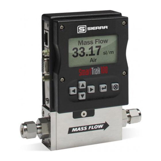
- Page 1 Sierra Instruments Instruction Manual SmartTrak 100 Series ® SmartTrak Series 100 ® Mass Flow Meters and Controllers Models: C100, M100, C101, and M101 Instruction Manual IM-100, Revision: V October 2021...
- Page 2 IMPORTANT CUSTOMER NOTICE: OXYGEN SERVICE Sierra Instruments, Inc. is not liable for any damage or personal injury, whatsoever, resulting from the use of Sierra Instruments standard mass flow meters or controllers for oxygen gas. You are responsible for determining if this mass flow meter or controller is appropriate for your oxygen application.
-
Page 3: Table Of Contents
Sierra Instruments Instruction Manual SmartTrak 100 Series ® Table of Contents Chapter 1: Introduction ..................... 5 Welcome to the future of gas flow measurement! ..............5 Using This Manual ......................... 5 Safety Information ........................6 Receipt of your instrument ..................... 7 The SmartTrak Flow Sensing Principle ................. - Page 4 Sierra Instruments Instruction Manual SmartTrak 100 Series ® Chapter 5: Digital Operation RS-232 & SmartTrak Software ........48 Power Up Your Instrument ....................48 Power Up Your Computer ....................50 Loading the SmartTrak Software ..................50 Connecting SmartTrak to Your Computer ................51 If your computer has a serial port…...
-
Page 5: Chapter 1: Introduction
CHAPTER 1: INTRODUCTION Welcome to the future of gas flow measurement! This manual is your guide to SmartTrak. Visit the Sierra Instruments website www.sierrainstruments.com any time for more information about this product. The SmartTrak instruments offer a variety of features for ease of operation. Among these features: ✓... -
Page 6: Safety Information
Sierra Instruments Instruction Manual SmartTrak 100 Series ® SAFETY INFORMATION Caution and warning statements are used throughout this book to draw your attention to important information. Warning! Caution! This statement appears with information that is important to This statement appears with information that is important for protect people and equipment from damage. -
Page 7: Receipt Of Your Instrument
(as ordered). Make sure any spare parts or accessories are not discarded with the packing material. Do not return any equipment to the factory without first contacting one of Sierra’s Technical Support Centers:... - Page 8 Sierra Instruments Instruction Manual SmartTrak 100 Series ® DEFINITIONS USED IN THIS MANUAL The following terms are used frequently in this manual. They are presented here with their definitions for your information. Setpoint—The command or control signal supplied to a flow controller is called its setpoint.
-
Page 9: The Smarttrak Flow Sensing Principle
Sierra Instruments Instruction Manual SmartTrak 100 Series ® THE CAPILLARY THERMAL OPERATING PRINCIPLE Watch Video: www.sierrainstruments.com/CapPrinciple. The operating principle of the SmartTrak instruments is based on heat transfer and the first law of thermodynamics. During operation process gas enters the instrument’s flow body and divides into two flow paths, one through the sensor tube, and the other through the laminar flow bypass. - Page 10 Sierra Instruments Instruction Manual SmartTrak 100 Series ® Figure 1-3. Sensor Temperature Distribution Figures 1-2 and 1-3 show the mass flow through the sensor tube as inversely proportional to the temperature difference of the coils. The coils are legs of a bridge circuit with an output voltage in direct proportion to the difference in the coils’...
- Page 11 Sierra Instruments Instruction Manual SmartTrak 100 Series ® plug, assumes the exact height above the valve’s orifice required to maintain the valve’s command flow (set point). The result is excellent resolution.
-
Page 12: Chapter 2 Installation
32°F (0°C) and ambient temperature is 0-50°C. If your Injury can result if line pressure exceeds the application exceeds any of these parameters, contact your Sierra Sales Agent before maximum rating of installation. You may also contact one of Sierra’s Technical Support Centers. FACTORY... -
Page 13: Installing The Instrument-Plumbing
2. Sierra strongly recommends you install an in-line filter upstream of the instrument. Recommended filter size: 10 micron. A 10 micron filter is available from Sierra as an accessory. See Appendix B or contact your local Sierra distributor. 3. Do not locate the instrument in areas subject to sudden temperature changes, excessive moisture or near equipment radiating significant amounts of heat. -
Page 14: Compression Fittings
Sierra Instruments Instruction Manual SmartTrak 100 Series ® Follow the installation instructions that are applicable to your instrument’s process connection. Ensure that the tubing is free from burrs or sharp rims that may result from cutting. CAUTION: Before use, all plumbing should be checked carefully for leaks, especially at the connecting fittings. -
Page 15: 1/4 Inch Female Npt
Sierra Instruments Instruction Manual SmartTrak 100 Series ® Position the instrument with the flow direction arrow pointing the direction of flow. Install new gaskets that are compatible with the gas to be used. Tighten the nut finger-tight, and then 1/8 turn tighter with a wrench. Do not over- tighten! Check the system’s entire flow path thoroughly for leaks. -
Page 16: Installing Your Instrument-Mechanical Mounting
® For this reason, special precautions need to be taken for use with CO₂. When you order the instrument, Sierra can equip it with 90D Viton® O-rings. For controllers, Sierra offers ValFlex™ valve seats that are more resistant. Sierra recommends avoiding depressurizing C100 CO₂ units if possible. If... -
Page 17: Installing Your Instrument-Electrical Connections
Sierra Instruments Instruction Manual SmartTrak 100 Series ® Alternately, you can lay the Remote Pilot Module on its back and insert the CAT-5 cable into the socket in the bottom. Installing your Instrument—Electrical Connections All electrical connections for your SmartTrak instrument are made on the left (inlet) side panel. - Page 18 Sierra Instruments Instruction Manual SmartTrak 100 Series ® SmartTrak is provided with a high density 15-pin D Connector called an “HD DB-15” located on the side of the enclosure and either one of our optional pre-assembled communications cables or an empty mating connector. Power must be supplied to the HD DB-15 connector.
- Page 19 The SmartTrak requires a 15-24 VDC power supply. If you are using the power supply supplied by Sierra, connect it to the 15-pin HD DB-15 connector on the side of the instrument. If you are supplying your own power source, it must be a regulated 15-24 VDC with ripple not to exceed 100 mV peak-to-peak.
- Page 20 Sierra Instruments Instruction Manual SmartTrak 100 Series ® Figure 2-5: Power Supply Requirements Instrument Type Recommended Input Minimum Current Voltage Required (mA) M100L Meter 15-24 VDC (+ 10%) M100M Meter 15-24 VDC (+ 10%) M100H Meter 15-24 VDC (+ 10%)
- Page 21 Sierra Instruments Instruction Manual SmartTrak 100 Series ® ▪ Valve Close: To force the valve closed, connect the black (pin 12) wire to pin 10 ▪ Purge: To force the valve to its maximum open position which we call “Purge,” connect the pink (pin 4) wire to the white (pin 11) wire.
- Page 22 Sierra Instruments Instruction Manual SmartTrak 100 Series ® CAUTION: The CAT-5 connector on the side of the SmartTrak is NOT an Ethernet connector. It is for use with the optional Remote Pilot Module or CRN cable. Do not plug an Ethernet...
-
Page 23: Chapter 3: Analog Operation
Power Your Instrument: Provide adequate power per Figure 2-5. Apply power using Sierra’s power supply or your own power source. The green LED at the top of the inlet side will light to confirm power. If your instrument has a Pilot Module, it will begin its start-up cycle. -
Page 24: Analog Operation, Mass Flow Controller
2. Power Your Instrument: Provide adequate power per Figure 2-5. Apply power using Sierra’s power supply or your own power source. The green LED at the top of the inlet side will light to confirm power. If your instrument has a Pilot Module, it will begin its start-up cycle. -
Page 25: Smarttrak Features
Manual Valve Override—Valve Close Manual valve override is provided for all Sierra mass flow controllers. This feature includes both a valve close command and a valve maximum open command (called purge). When the valve is directed to close or to purge, it will no longer respond to a... -
Page 26: Manual Valve Override-Valve Purge Function
Sierra Instruments Instruction Manual SmartTrak 100 Series ® FOR VALVE CLOSE: connect pin 12 to analog ground Remember that the valve in the SmartTrak is not a positive shut-off device. The Controller will return to normal automatic operation about 4 seconds after pin 12 is left floating. - Page 27 Material Safety Data Sheet (MSDS) must be enclosed & attached to the outside of the box to alert Sierra personnel of the potential hazard. Also, make sure the inlet & outlet are securely sealed.
-
Page 28: Chapter 4: Digital Operation With Pilot Module
Sierra Instruments Instruction Manual SmartTrak 100 Series ® CHAPTER 4: Digital Operation with Pilot Module Your SmartTrak instrument may be operated in three different ways: THREE CONTROL OPTIONS A. Analog Input/Output Operation (Chapter 3): Using analog input/output signals at the HD DB-15 connector. - Page 29 Next, place the other end into one of the two matching jacks on the Pilot Module. For your convenience, Sierra has provided two jacks—one on the back and one on the bottom of the Remote Pilot Module. You may use whichever jack is most convenient for your application as they both have identical functions.
-
Page 30: Pilot Module Operation, Mass Flow Meters
Sierra Instruments Instruction Manual SmartTrak 100 Series ® These are shown in the photo below: Up, Down Escape Left, Right Enter Pilot Module Operation, Mass Flow Meter After your instrument is installed and the system has undergone a complete leak check as discussed in detail in Chapter 2, follow these steps: 1. - Page 31 Controller before it was shut down, you must assume that the valve will open when power is applied. TAKE NECESSARY PRECAUTIONS. 2. Power Up Your Instrument: Apply power to your instrument using Sierra’s power supply or your own input power source. See Chapter 2, Figure 2-5: Power Supply Requirements.
- Page 32 Sierra Instruments Instruction Manual SmartTrak 100 Series ® Mass Flow 0.000 sl/m NOTE: If gas is flowing and the Pilot Module has a setpoint greater than zero, it will immediately begin to accurately display the gas mass flow rate on the LCD panel. If you have chosen alternate units or another gas, the display will show the selected units instead of those above.
- Page 33 Sierra Instruments Instruction Manual SmartTrak 100 Series ® ❖ Valve operation mode (normal, valve close or purge) ❖ Current meter full scale value with units (user selectable) 2 Lower Level Screens: permit changes to instrument operation. They are password protected.
- Page 34 Sierra Instruments Instruction Manual SmartTrak 100 Series ® Map of the Pilot Module Interface The Pilot Module user interface is presented below in a graphical format. Once you have some familiarity with the user interface, you may find you want to make a copy of this and keep it with the instrument for reference.
- Page 35 Sierra Instruments Instruction Manual SmartTrak 100 Series ® The seven Upper Level Screens display a variety of information. You are able to move between the screens by pressing the left or right arrows. No password is required for the Upper Level Screens.
- Page 36 Sierra Instruments Instruction Manual SmartTrak 100 Series ® The state of the valve can be: 1. Closed (Remember that the SmartTrak is not a positive shut-off device). 2. Purge--Maximum Open (recommended 120% of the calibrated full scale value, but can be much more and can be dangerous) 3.
- Page 37 Sierra Instruments Instruction Manual SmartTrak 100 Series ® Lower Level Screens (Changing Parameters) Getting to the Lower Level Screens: Your instrument is password protected so that unauthorized personnel will be unable to change the operating parameters of SmartTrak. To enter the Lower Level Screens at any time you must first supply the correct password.
-
Page 38: Making Changes Using The Lower Level Screens
When you press any button, you will return to the Mass Flow Screen in the Upper Level. Press the “enter” key to try again. LOST PASSWORDS & GENERAL CUSTOMER SERVICE: If you lose your password, it will be necessary to contact one of Sierra’s Technical Support Centers. Email Customer Service: service@sierrainstruments.com FACTORY USA Customer Service:... - Page 39 Sierra Instruments Instruction Manual SmartTrak 100 Series ® This is the position where you can change the setpoint value of the mass flow controller. To make a change to the displayed value, press the enter key. The first number in the display will blink.
- Page 40 Sierra Instruments Instruction Manual SmartTrak 100 Series ® Change Units Screen If you are already in the Lower Level Screens, push the right or left arrow until you reach the Change Units screen. To get to this screen at any time, Press Escape—Press Enter—...
- Page 41 Sierra Instruments Instruction Manual SmartTrak 100 Series ® You can make additional changes by using the left and right arrow keys to move to other Lower Level Screens. You may also choose to press the escape key to return to the Upper Level Screens and to observe your change.
- Page 42 Sierra Instruments Instruction Manual SmartTrak 100 Series ® Automatic From this screen you may set the valve to open all the way (“Purge”), force the valve to remain closed until further changes are made (“Valve Closed”) or set the valve to control flow when it receives a setpoint from some source (“Automatic”).
- Page 43 Sierra Instruments Instruction Manual SmartTrak 100 Series ® setpoint command signal from the Pilot Module or a computer using the RS-232 link, the display must show: Change Setpoint Source Pilot/RS232 If, instead of using the Pilot Module or the RS-232 link, you prefer to supply an analog setpoint signal to the SmartTrak, press the enter button.
- Page 44 Sierra Instruments Instruction Manual SmartTrak 100 Series ® Change Output Signals 0-5 VDC/0/4-20 mA Here you can re-configure the analog output signals for the instrument. The SmartTrak always outputs one current signal of 0/4-20mA but the voltage signal may be selected using this screen.
- Page 45 Sierra Instruments Instruction Manual SmartTrak 100 Series ® The accuracy is always 1% of full scale under calibration conditions of the original factory full-scale calibration value. Caution: For any instrument, if a value greater than the factory full scale calibration value is entered on this screen, the SmartTrak will modify the requested value to equal the factory full scale calibration value.
- Page 46 Sierra Instruments Instruction Manual SmartTrak 100 Series ® Keep in mind that you can change the span for each individual gas, thus, a change in the span to one gas will not affect the span of another gas. You can make additional changes by using the left and right arrow keys to move to other Lower Level Screens.
-
Page 47: Lost Passwords And General Customer Service
Lost Passwords and General Customer Service The “creator” password is 6363- this will override all other passwords. If this does not work, it will be necessary to contact one of Sierra’s Technical Support Centers. Email Customer Service: service@sierrainstruments.com FACTORY USA Customer Service:... -
Page 48: Chapter 5: Digital Operation Rs-232 & Smarttrak Software
If you prefer to write your own software to communicate with the SmartTrak over the RS- 232 link, this is certainly possible. Sierra Instruments will provide the Source Code including the Command Set upon request. Unfortunately, this is the limit of software Technical Support we can extend. - Page 49 After your instrument is installed and the system has undergone a complete leak check (discussed in detail in Chapter 2), apply power using Sierra’s power supply or your own input power source. See Chapter 2, for power supply requirements. The green LED at the top of the left side will light.
-
Page 50: Power Up Your Computer
Sierra Instruments Instruction Manual SmartTrak 100 Series ® CAUTION: If you do not know the position of the valve before it was shut down, you must assume that the valve will open when power is applied. Take necessary precautions. Power Up Your Computer Apply power to your computer per the manufacturer’s recommendations. -
Page 51: Connecting Smarttrak To Your Computer
® If your computer has a serial port… We suggest you use the optional Sierra Instruments RS-232 communication cable (part number CRN). This pre-manufactured cable has the correct DB9 connection to mate with most computers and a CAT 5 connector which should be connected to the jack on the side of your new instrument. -
Page 52: If Your Computer Has No Serial Port, But Has A Usb Port
Sierra Instruments Instruction Manual SmartTrak 100 Series ® CAT 5 HD DB 15 Figure 5-1: SmartTrak Connections If you do not have the Pilot Module display, you can connect pins 7 (serial transmit), 13 (serial receive) and 3 (analog ground) on the instrument’s 15-pin mini- D Connector to an appropriate serial port using a standard DB-9 connector instead of using the supplied CRN cable (see Chapter 2 for wiring instructions). -
Page 53: If You Plan To Control More Than One Smarttrak Instrument From Your Computer
USB ports as outlined in the sections above. Open a separate software window for each meter and you can monitor all of them at one time. If connecting your computer to the SmartTrak creates any confusion, please contact Sierra Instruments or your IT person for assistance. - Page 54 Sierra Instruments Instruction Manual SmartTrak 100 Series ® Select the comport pull down menu: Use the pull-down menu to choose the port number that corresponds to the serial port channel your SmartTrak is connected to (from 1 to 255). If you have only one serial port, select “Comm Port 1.”...
- Page 55 Sierra Instruments Instruction Manual SmartTrak 100 Series ® Proceed to the next section. If the screen appears, but the yellow and white boxes are all empty, you have selected the wrong “Com Port number.” See the section titled “Com Port” on page 5-16 for instructions on how to change the communication port number.
- Page 56 Sierra Instruments Instruction Manual SmartTrak 100 Series ® Using the SmartTrak Software A. Upper Section of Software Window Across the upper half of the SmartTrak Software window you will see 3 yellow boxes. These are titled: ❖ Flow ❖ Setpoint (flow controllers only. Will show zero for meters) ❖...
- Page 57 Sierra Instruments Instruction Manual SmartTrak 100 Series ® Flow The box displays the mass flow rate, the engineering units, the gas choice and the analog output choice. Setpoint If you have a Mass Flow Meter, this box is zero (as shown above). The Setpoint box displays...
- Page 58 (Purge) or closed (Closed). See the section titled “Change Valve Operation” below for further instructions Full Scale This screen displays the current full-scale value of the instrument with engineering units. It also displays the com port selected and a counter for the com port (for Sierra Troubleshooting only).
- Page 59 Sierra Instruments Instruction Manual SmartTrak 100 Series ® B. Lower Section of Software Window– Changing Parameters Across the bottom half of the screen you will find a number of white boxes. Each box allows you to adjust one or more meter functions. The various functions are reviewed in the following section.
- Page 60 Sierra Instruments Instruction Manual SmartTrak 100 Series ® Change Valve Operation –Automatic, Close, Purge This function enables or overrides any setpoint command given to the SmartTrak. At Automatic: start-up, the box will show In this normal operating position, the valve is ready to control flow when it receives a setpoint from some source.
- Page 61 Sierra Instruments Instruction Manual SmartTrak 100 Series ® Choose the correct gas for your current application and click. The new gas selection will appear in the box. Within a few seconds, the new gas selection will also appear in the yellow Flow box and the values of the mass flow, setpoint and the full scale will be adjusted for this new gas.
- Page 62 Sierra Instruments Instruction Manual SmartTrak 100 Series ® C: ADJUSTMENTS: Clicking on “adjustments” brings up the meter settings screen.
- Page 63 Sierra Instruments Instruction Manual SmartTrak 100 Series ® This screen allows for zeroing, spanning and adjusting the full scale for each of the 10 gases in the gas table individually. The screen will be displayed for the gas selected in the gas table on the main screen Caution: the values in this screen can be set individually for each of the 10 gases.
- Page 64 Sierra Instruments Instruction Manual SmartTrak 100 Series ® offset. Also, the best zero is obtained by using the actual gas at the listed operating pressure. After 30 minutes, if your zero reading and/or calibration are off (i.e. show flow at zero), we recommend that you perform the re-zeroing procedure.
- Page 65 Sierra Instruments Instruction Manual SmartTrak 100 Series ® For example, the meter reads 98. The desired reading is 100. A span value of 1.02 will adjust the meter output to read 100. Caution: this number should not be adjusted beyond 0.8 to 1.2.
- Page 66 Sierra Instruments Instruction Manual SmartTrak 100 Series ® The instrument’s maximum flow rate is also recorded on the data label (at the back of the instrument) and on the calibration certificate. You may select any full-scale value between 100% and 50% of the maximum full-scale value.
- Page 67 Sierra Instruments Instruction Manual SmartTrak 100 Series ® Here are some guidelines to remember if you choose to modify the Full Scale Value: Changing the full-scale value of the instrument does not affect the accuracy of the measurement. Instrument accuracy is a percentage of the original factory full-scale value If you enter a full-scale value beyond the instrument’s calibrated maximum range, the...
- Page 68 Sierra Instruments Instruction Manual SmartTrak 100 Series ® Read Controller Parameters Use this function if you believe your computer and your SmartTrak instrument may have stopped communicating. It is essentially a re-boot command for the SmartTrak microprocessor. When you switch Comm Ports, it is recommended that you use this function.
-
Page 69: Chapter 6: Technical Support & Service
Verify that your settings and adjustments are consistent with factory recommendations. If the problem persists, Sierra is eager to help you. You may contact us at any of the following Technical Support Centers. It may also help to call your Sierra Sales Agent, who is also well trained in the operation of the product. -
Page 70: Factory Calibration-All Models
To request a rough estimate of the pricing, contact your local Sierra Instruments distributor or contact one of our offices directly. A detailed quote will be provided following a full evaluation of your instrument. - Page 71 WARNING: If an instrument used with a toxic or corrosive gas is returned to the factory, a Material Safety Data Sheet (MSDS) must be enclosed & attached to the outside of the box to alert Sierra personnel of the potential hazard. Also, make sure the inlet & outlet...
- Page 72 Sierra Instruments Instruction Manual SmartTrak 100 Series ® Appendix A: C100/M100 SmartTrak Product Specifications, Dimensions and Mounting...
- Page 73 Sierra Instruments Instruction Manual SmartTrak 100 Series ®...
- Page 74 Sierra Instruments Instruction Manual SmartTrak 100 Series ®...
- Page 75 Sierra Instruments Instruction Manual SmartTrak 100 Series ®...
- Page 76 Sierra Instruments Instruction Manual SmartTrak 100 Series ®...
- Page 77 Sierra Instruments Instruction Manual SmartTrak 100 Series ®...
- Page 78 Sierra Instruments Instruction Manual SmartTrak 100 Series ®...
- Page 79 Sierra Instruments Instruction Manual SmartTrak 100 Series ® Appendix B: C101/M101 MicroTrak™ Product Specifications...
- Page 80 Sierra Instruments Instruction Manual SmartTrak 100 Series ®...
- Page 81 Sierra Instruments Instruction Manual SmartTrak 100 Series ®...
- Page 82 Sierra Instruments Instruction Manual SmartTrak 100 Series ® Appendix C: Gas Tables & K-factors (same for all 100 Series) SmartTrak Pre-programmed Gases: Dial-A-Gas The following gases have been programmed into the SmartTrak instrument in this order. If you are using one of these gases, you may use the Dial-A-Gas feature in either the Pilot Module or the Software Package and the instrument will adjust the outputs automatically.
- Page 83 Sierra Instruments Instruction Manual SmartTrak 100 Series ® Gas Tables and K-factors NOTE: If no O-ring material is specified then O-ring to be used is Viton. NEO is neoprene or equivalent. KR is DuPont Kalrez or equivalent. Valve Seat applies only to controllers.
- Page 84 Sierra Instruments Instruction Manual SmartTrak 100 Series ® Chemical K-factor Density Density Elastomers* Relative to Actual Gas Symbol (Cal/g) (g/l) @ 70°F (g/l) @ 0°C O-ring Valve Seat Cyanogen 0.611 0.2613 2.156 2.322 Viton® Cyanogen Chloride CICN 0.611 0.1739 2.545 2.742...
- Page 85 Sierra Instruments Instruction Manual SmartTrak 100 Series ® Chemical K-factor Density Density Elastomers* Relative to Air Actual Gas Symbol (Cal/g) (g/l) @ (g/l) @ O-ring Valve 70°F 0°C Seat Hexafluoroethane 0.241 0.1834 5.716 6.157 Viton® (Freon-116) Hexane 0.18 0.3968 3.569 3.845...
- Page 86 Sierra Instruments Instruction Manual SmartTrak 100 Series ® Chemical K-factor Density Density Elastomers* Relative to Air Actual Gas Symbol (Cal/g) (g/l) @ (g/l) @ O-ring Valve Seat 70°F 0°C Phosgene COCl 0.441 0.1394 4.101 4.418 Viton® Phosphine 0.762 0.2374 1.408 1.517...
- Page 87 Sierra Instruments Instruction Manual SmartTrak 100 Series ® Appendix D: (same for all Flow Chart for Pilot Module User Interface 100 Series) NOTE: If you press the escape key at any time, you will immediately return to the main Mass Flow screen in the Upper Level.
- Page 88 Sierra Instruction Manual SmartTrak Series 100 ® Appendix E: PIN Configuration (same for all 100 Series) Figure 2-4: Wiring Definitions for Optional Communication Cable Pin # Wire Color in Cable Function Brown Analog Ground/Output 0-5 VDC Output (or 0-10, 1-5 VDC )
- Page 89 This document is for firmware version 2.044. Sierra Instruments, Inc. reserves the right to change the command set without notification to the user. However, Sierra will also make every effort to maintain backwards compatibility with previously published command sets for ®...
- Page 90 Sierra Instruction Manual SmartTrak Series 100 ® ASCII STRING COMMANDS '?Flow + CRC + cr' Version 2.xx read command '!Flow + value + CRC + cr' Version 2.xx write command '?Flow + CRC + cr' Version 1.xx read command Returns ASCII string 'Flow + value + CRC + cr' Values are a string of digits and an optional decimal place: '10.00'...
- Page 91 Sierra Instruction Manual SmartTrak Series 100 ® SETPOINT_RAM DESCRIPTION SETPOINT_RAM returns the current ram memory value setpoint with read command. The write command sets the ram memory value and makes it the active setpoint. ASCII STRING COMMANDS '?Setr + CRC + cr' Version 2.xx read command '!Setr + value + CRC + cr' Version 2.xx write command...
- Page 92 Sierra Instruction Manual SmartTrak Series 100 ® ASCII STRING COMMANDS '?Vlvi + CRC + cr' Version 2.xx read command '!Vlvi + valveIndex + CRC + cr' Version 2.xx write command '?Vlvi + CRC + cr' Version 1.xx read command 'Vlvi + valveIndex + CRC + cr' Version 1.xx write command...
- Page 93 Sierra Instruction Manual SmartTrak Series 100 ® streamString = "On", "Off", "Echo" CRC=redundancy check bytes; cr=carrage return byte. VERSION_NUMBER DESCRIPTION VERSION_NUMBER returns the firmware version. This is useful when Ver. 1.xxx and 2.xxx are in the same system to determine which command to send.
- Page 94 Sierra Instruction Manual SmartTrak Series 100 ® Returns ASCII string 'Sync + "" + CRC + cr' SyncEvent returned last to indicate all events have been sent CRC=redundancy check bytes; cr=carrage return byte. ZERO DESCRIPTION ZERO sets the flow offset value to a zero flow reading. Warning: All flow must be shut off, the unit needs to be at pressure with the gas being used.
- Page 95 Sierra Instruction Manual SmartTrak Series 100 ® /* this for loop starts with ASCCII ‘S’ and loops through to the last ASCII ‘0’ */ crc=crc^((uint)(cmnd[i]*0x0100)); /* the ASCII value is times by 0x0100 first then XORED to the current crc value */ for(j=0;...
- Page 96 Sierra Instruction Manual SmartTrak Series 100 ® crc=(crc<<1)&0xffff; if((crc&0xff00)==0x0d00) crc +=0x0100; if((crc&0x00ff)==0x000d) crc +=0x0001; if((crc&0xff00)==0x0000) crc +=0x0100; if((crc&0x00ff)==0x0000) crc +=0x0001; return crc; CRC ROUTINE IN MS VISUAL BASIC: Public Sub SendPacket(packet As String) Dim crcBytes() As Byte Dim crcLen, vpacket...
- Page 97 Sierra Instruction Manual SmartTrak Series 100 ® If (crcWord And &HFF) = &H0 Then ' zero char is death crcWord = crcWord + 1 ' make this byte &hxx01 End If ReDim Preserve crcBytes(0 To crcLen + 3) ' make room for crc and carriage return crcBytes(crcLen + 1) = Int(crcWord / &H100) ' high byte...
- Page 98 Appendix G: Warranty Policy LIMITED WARRANTY POLICY- REGISTER ONLINE All Sierra products are warranted to be free from defects in material and workmanship and will be repaired or replaced at no charge to Buyer, provided return or rejection of product is made within a reasonable period but no longer than one (1) year for calibration and non-calibration defects, from date of delivery.
Need help?
Do you have a question about the SmartTrak C100 and is the answer not in the manual?
Questions and answers