Advertisement
Overview
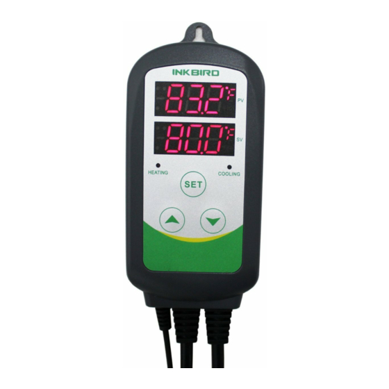
What is ITC-308?
ITC-308 is an easy-to-use, safe and reliable dual relay output temperature controller. It can be used as over-temperature protection and automatic temperature control system for various electric appliances such as equipment for home-brew, aquarium, pet breeding, incubation, BBQ, seedling heat mats, oven temperature control, terrestrial heat control, constant temperature cycle of heating pump, culture fermentation, accelerating germination, electric radiator, electric oven, etc.
This product has plug-n-play design with dual relay, be able to connect with refrigeration and heating equipment easily to realize ideal temperature control. It's equipped with dual LED display, and offers display options of Centigrade and Fahrenheit, enabling more humanized temperature control. With large output power 1200W(110V) / 2200W(220V), it's suitable for most applications.
ITC-308 is designed with compressor delay protection for refrigeration, high and low temperature alarm, and sensor fault alarm, which makes the temperature controller more safe and reliable. Functions such as temperature calibration, separately set differential for refrigeration and heating, enable more accurate temperature control.
Main features
- Plug and play design, easy to use;
- Dual relay output, be able to connect with refrigeration and heating equipment at the same time;
- Support reading with Centigrade or Fahrenheit unit;
- Maximum output load: 1200W(110V) / 2200W(220V);
- Dual display window, be able to display measured temperature and set temperature at the same time;
- Temperature calibration;
- Compressor delay protection for refrigeration control;
- High and low temperature alarms are available;
- Over-temperature and sensor fault alarm;
- Heating/cooling differential function could be set separately for refrigeration and heating to protect temperature controller from violent change.
Specification
| Temperature Control Range | -50~99°C / -58~210°F |
| Temperature Resolution | 0.1°C / 0.1°F |
| Temperature Accuracy | ±1°C (-50 ~ 70°C) / ±1°F (-50 ~ 160°F) |
| Temperature Control Mode | On/Off Control, Heating and Cooling |
| Input Power | 100 ~240VAC, 50Hz/60Hz |
| Temperature Control Output | Max. 10A, 100V ~240V AC |
| Buzzer Alarm | High and Low Temperature Alarm |
| Sensor Type | NTC sensor (Including) |
| Sensor Length | 2m / 6.56ft |
| Relay Contact Capacity | Cooling (10A, 100-240VAC) |
| Heating (10A, 100-240VAC) | |
| Input Power Cable Length | 1.5m (5ft) |
| Output Power Cable Length | 30cm (1ft) |
| Dimension | Main Body: 140x68x33mm (5.5x2.7x1.3 inch) Socket (US Version): 85x42x24mm (3.3x1.7x1.0 inch) Socket (EU Version): 135x54x40mm (5.3x2.1x1.6 inch) Socket (UK Version): 140x51x27mm (5.5x2.0x1.0 inch) |
| Ambient Temperature | -30~ 75°C / -22~ 167°F |
| Storage | Temperature -20~ 60°C / -4~ 140°F |
| Humidity 20~85% (No Condensate) | |
| Warranty | 1 Year |
Keys Instruction

- PV: Process Value. under running mode, display current temperature; under setting mode, display menu code.
- SV: Setting Value. under running mode, display setting temperature; under setting mode, display setting value.
- Cooling indicator Lamp: when the light is on, start refrigeration; when the light is flickering, the compressor is under delay protection.
- Heating Indicator Lamp: when the light is on, start heating.
- SET key: press SET key for 3 seconds to enter menu for function setting. During the setting process, press SET key for 3 seconds to quit and save setting changes.
- DECRESE key: under running mode, press DECRESE key to inquiry CD value; under setting mode, press DECRESE key to decrease value.
- INCREASE key: under running mode, press INCREASE key to inquiry HD value; under setting mode, press INCREASE key to increase value.
- Heating Device Socket: this socket is for heating output.
- Cooling Device Socket: the socket is for refrigeration output.
Key Operation Instruction
Enquiry Set Point
When the controller is working normally, short press " ![]() " key for one time, then the heating differential (HD) will be displayed; short press "
" key for one time, then the heating differential (HD) will be displayed; short press "![]() " for one time, then the cooling differential (CD) will be displayed. The screen will return to normal display mode after 2 seconds.
" for one time, then the cooling differential (CD) will be displayed. The screen will return to normal display mode after 2 seconds.
How to Set Parameters
When the controller is working normally, press "SET" key for over 3 seconds to enter parameters set up mode. "SET" indicator lamp will on. PV window displays the first menu code "TS", while SV window displays according setting value. Press "SET" key to go to next menu and display according menu code, press " ![]() " key or "
" key or " ![]() "key to set current parameter value. After setting done, press "SET" key for 3 seconds at any time to save the parameters change and return to normal temperature display mode. During setting, if there is no operation for 10 seconds, the system will quit setting mode and return to normal temperature display mode without saving the parameters change.
"key to set current parameter value. After setting done, press "SET" key for 3 seconds at any time to save the parameters change and return to normal temperature display mode. During setting, if there is no operation for 10 seconds, the system will quit setting mode and return to normal temperature display mode without saving the parameters change.
Setup Flow Chart

Menu Instruction
When the temperature is displayed in Centigrade
| Menu code | Function | Setting range | Default setting | Remarks |
| TS | Temperature Set Value | -50~99.9℃ | 25℃ | 5.1 |
| HD | Heating Differential Value | 0.3~15℃ | 2.0℃ | |
| CD | Cooling Differential Value | 0.3~15℃ | 2.0℃ | |
| AH | Alarm High Limit | -50~99.9℃ | 90℃ | 5.2 |
| AL | Alarm Low Limit | -50~99.9℃ | -40℃ | |
| PT | Compressor Delay | 0~10 minutes | 3 minutes | 5.3 |
| CA | Temperature Calibration | -15℃~15℃ | 0℃ | 5.4 |
| CF | Display in Fahrenheit or Centigrade | C | 5.5 |
When the temperature is displayed in Fahrenheit
| Menu code | Function | Setting range | Default setting | Remarks |
| TS | Temperature Set Value | -50~210℉ | 77℉ | 5.1 |
| HD | Heating Differential Value | 1~30℉ | 3℉ | |
| CD | Cooling Differential Value | 1~30℉ | 3℉ | |
| AH | Alarm High Limit | -50~210℉ | 200℉ | 5.2 |
| AL | Alarm Low Limit | -50~210℉ | -40℉ | |
| PT | Compressor Delay | 0~10 minutes | 3 minutes | 5.3 |
| CA | Temperature Calibration | -15℃~15℉ | 0℉ | 5.4 |
| CF | Display in Fahrenheit or Centigrade | F | 5.5 |
Temperature Control Range Setting (TS, HD, CD)
When the controller is working normally, the LED displays current measured temperature, and automatically identify and switch refrigeration and heating working modes. When the measured temperature PV ≥ TS(temperature set value) + CD (cooling differential value), system enters refrigeration status, the cool indicator lamp will on, and refrigeration relay starts to work; when the cool indicator lamp is flickering, it means the refrigeration equipment is under compressor delay protection status. When the measured temperature PV≤TS (temperature set value), the cool indicator lamp will off, and the refrigeration relay stops working.
When the measured temperature PV≤TS (temperature set value)-HD (heating differential value), system enter heating status, the heat indicator lamp will on, and heating relay starts to work; when the measured temperature PV≥ TS(temperature setting), the heat indicator lamp will of, and heating relay stops working.
For example, set TS=25°C, CD=2°C, and HD=3°C, then when measured temperature is higher or equal to 27°C(TS+CD), system enters refrigeration status; when temperature decline to 25°C(TS), stop refrigeration; when measured temperature is lower or equal to 22°C(TS-HD), system enters heating status; when the temperature raised to 25°C(TS), stop heating.
In case the time interval between two refrigeration is less than PT, please refer to 5.3.
Alarm High/Low Limit Setting (AH, AL)
When measured temperature is higher or equal to AH, high temperature alarm will be triggered, buzzer will alarm with tone "bi-bi-Biii" until the temperature is lower than AH or any key is pressed.
When measured temperature is lower or equal to AL, low temperature alarm will be triggered, buzzer will alarm with tone "bi-bi-Biii" until the temperature >AL or any key is pressed.
Compressor Delay (PT)
Under refrigeration mode, after power on, if the measured temperature is higher than the value of setting temperature (TS) plus cooling differential (CD), the equipment won't start refrigeration immediately, but waiting for a delay time. When the time interval between two refrigeration operation is larger than preset delay, the equipment will start refrigeration immediately; when the time interval between two refrigeration is less than preset delay, the equipment won't start refrigeration until preset delay is satisfied. Delay time will be calculated right after the moment refrigeration stops.
Temperature Calibration (CA)
When there is deviation between measured temperature and actual temperature, use temperature calibration function to align the measured temperature and actual temperature. The corrected temperature is equal to temperature before calibration plus corrected value (corrected value could be positive value, 0 or negative value).
Display in Fahrenheit or Centigrade unit (CF)
Users can select display with Fahrenheit or Centigrade temperature value according to their own habit. Default setting is display with Centigrade temperature value. For displaying with Fahrenheit temperature value, set CF value as F. Attentions: when CF value changed, all the setting value will be recovered to factory settings.
Error Description
Sensor Fault Alarm
When temperature sensor is in short circuit or open loop, the controller will initiate sensor fault mode, and cancel all the actions. The buzzer will alarm, LED displays ER. Buzzer alarm could be dismissed by pressing any key. After faults solved, the system will return to normal working mode.
Over-temperature Alarm
When measured temperature exceeds the measuring range (less than -50°C /-58°F or higher than 99°C/210°F), the controller will initiate over-temperature alarm mode, and cancel all the actions. The buzzer will alarm, LED displays HL. Buzzer alarm could be dismissed by pressing any key. When temperature returns to measuring range, the system will return to normal working status.
Technical Assistance and Warranty
Technical Assistance
If you have any problems installing or using this thermostat, please carefully and thoroughly review the instruction manual. If you require assistance, please write us to cs@ink-bird.com. We will reply your emails in 24 hours from Monday through Saturday. You can also visit our web site www.ink-bird.com to find the answers of the common technical questions.
Warranty
INKBIRD TECH. C.L. warrants this thermostat for one years from the date of purchase when operated under normal condition by the original purchaser (not transferable), against defects caused by INKBIRD's workmanship or materials. This warranty is limited to the repair or replacement, at INKBIRD's discretion, of all or part of the thermostat. The original receipt is required for warranty purposes. INKBIRD is not responsible for injury property damage or other consequential damages or damages of third parties arising directly from an actual or alleged in mater of workmanship of the product. There are no representations, warranties, or conditions, express or implied, statutory or otherwise, other than herein contained in the sale of goods act or any other statue.
Contact Us
Business Contact: sales@ink-bird.com
Technical Support: cs@ink-bird.com
Business Hours: 09:00-18:00(GMT+8) from Monday to Friday
URL: www.ink-bird.com
Copyright
Copyright© 2016 Inkbird Tech. Co., Ltd. All rights reserved. No part of this document may be reproduced without prior written permission.
Disclaimer
Inkbird has made every effort to ensure that the information contained in this document is accurate and complete; however, the contents of this document are subject to revision without notice. Please contact Inkbird to ensure you have the latest version of this document.

Inkbird Tech. Co., Ltd.
VideosInkbird WiFi ITC-308 - How to Program Video
Documents / Resources
References
Download manual
Here you can download full pdf version of manual, it may contain additional safety instructions, warranty information, FCC rules, etc.
Advertisement


Need help?
Do you have a question about the ITC-308 and is the answer not in the manual?
Questions and answers