Table of Contents
Advertisement
Quick Links
Thank you very much for selecting INKBIRD products.
Read the instruction manual carefully before use, for right application and maintenance.
█ Safety Precautions
●Ensure the product using within the specification.
●Do not touch the terminals at least while power is being supplied. Doing so may occasionally result in injury due to electric shock.
●Do not allow pieces of metal, wire clippings, or fine metallic shaving or filings from installation to enter the product. Doing so may occasionally result in electric shock, fire, or malfunction.
●Do not use the product where subject to flammable or explosive gas. Otherwise, injury from explosion may occasionally occur.
●Never disassemble, modify or repair the product or touch any of the internal parts. Electric Shock, fire, or malfunction may occasionally occur.
●If the output relays are used past their life expectancy, contact fusing or burning may occasionally occur. Always consider the application conditions and use the output relays within their rated load and electrical life
The life expectancy of output relays varies considerably with the output load and switch conditions.
█ Main Features
●Front Panel Dimension: DIN (48WmmX48Lmm), Cutout size: 45x45mm
●Support Multiple Thermocouples and Resistance Sensors (K, S, Wre, T, E, J, B, N, CU50, PT100)
●Wide Controlling Range: -50~1300º C (K sensor)
●High Accuracy of Displaying and Controlling 0.1º C, Accuracy of Measurement ±0.2%FS
●PID and ON/OFF Control Mode, High Standard Self-adjusting Function
●Multiple Outputs and Alarm Modes
●Build-in Adjustable Digital Filter Reduce Interference
●The Self-adjusting Function and Intelligent Control of the Instrument Ensure the Long-term Stability
● High Luminance, 0.39" height LED display, Anti-glare panel
●Built-in Switch Power Supply, Wide Voltage Range and Low-power Consumption
█ Specification
Degree Celsius (<1000º C)
●Units:
●Power Supply Voltage:
AC 100-240V ±10% 50/60Hz
AC/DC 12-24V ±10%
DC 12-24V ±10%
●Operating voltage range:
85~110% Rated voltage
●Power Consumption:
Approx. 5VA(100~240VAC)
Approx. 4VA(12~24VAC)
Approx. 3W(12~24VDC)
●Display Character:
PV: 4 digital 9.9mm height Red LED Letters
SV: 4 digital 8mm height Green LED Letters
●Display Accuracy:
±0.2%FS 0.1º C(<1000º C);1º C(≥1000º C)
●Period of Sampling:
0.5S
●Temperature Compensation:
0-50º C
●Main Output:
Relay Contact Output (ITC-100R):
Voltage Pulses Output (ITC-100V):
●Life Expectancy of Relay: Mechanical≥10,000,000 operations
●Weight: Approx. 140g
●Environmental Conditions:
-10~55º C(no icy or condensation), RH 35-85% Humidity
●Storage Temperature: -25~65º C(no icy or condensation)
●Data Storage: 10year
●Mounting Method: Flush mounting and screw terminals
█ Connection
●Dimension (unit: mm)
Shell
· Push the instrument into the hole of panel and insert mounting bracket from back side,
· Ensure that the ambient temperature should not be exceed the specified working temperature, especially when installed more than two instruments.
●Connection
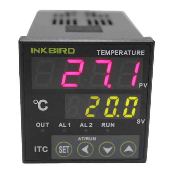
█ Front Panel and Operation
●PV Process Value
Measured Value/Mode Value
●SV Set Value
Set Value/ Mode Context Value
●Status Display LED
OUT:Output pilot lamp
AL1:Alarm1 pilot lamp
AL2:Alarm2 pilot lamp
RUN:Manual pilot lamp
●Up Key:
●Down Key:
{
●Move Key: When setting temperature value or parameter, press
●Self-Adjustment Key: When SV/PV at normal display, keep pressing the "《 " Key more than 2S to start or end self-adjusting function.
●Shift Key: When SV/PV at normal display, press "《 " Key less than 1S to shift between automatic and manual control modes.
●SET Key: When SV/PV at normal display, press the SET key to check PV and SV value, keep pressing it more than 2 seconds can access parameter setting mode.
PID Temperature Controller
50/60Hz
AC250V 3A (Resistive load) ON/NC.
Alarm 1 AC250V 3A (Resistive load) ON/NC.
DC 12V, 30mA;
Alarm 1 AC250V 3A (Resistive load) ON/NC
Electrical≥10,000,000 operations
Mounting bracket
Increase the value in setting, Keep pressing can increase value quick.
Decrease the value in setting, Keep pressing can increase value quick.
Manual
Panel Cutout
ensure that there are no gaps between the panel and mounting bracket, and then screw cap down.
"《 " Key to switch to the value needed
Model: ITC-100
Advertisement
Table of Contents

Related Manuals for Inkbird ITC-100


Summary of Contents for Inkbird ITC-100
- Page 1 PID Temperature Controller Manual Model: ITC-100 Thank you very much for selecting INKBIRD products. Read the instruction manual carefully before use, for right application and maintenance. █ Safety Precautions ●Ensure the product using within the specification. ●Do not touch the terminals at least while power is being supplied. Doing so may occasionally result in injury due to electric shock.
- Page 2 LOC parameters themselves. User can set all parameters only when setting LOC value is “2”, “40” or “808”. Details are as follows: INKBIRD TECH. CO. LTD. Loc=0, Temperature setting value and EP1-EP8 can be revamped. Loc=1, Data can not be revamped, only can be checked.(Except LOC parameters) www.ink-bird.com...
Need help?
Do you have a question about the ITC-100 and is the answer not in the manual?
Questions and answers