Table of Contents
Advertisement
Quick Links
Advertisement
Table of Contents

Subscribe to Our Youtube Channel
Related Manuals for ADTRAN 1200222L1


Summary of Contents for ADTRAN 1200222L1
- Page 1 HDLC Module User Manual Part Number 1200222L1 61200222L1-1A November1998...
- Page 2 901 Explorer Boulevard P.O. Box 140000 Huntsville, AL 35814-4000 (256) 963-8000 © 1998 ADTRAN, Inc. All Rights Reserved. Printed in U.S.A.
- Page 3 YEAR 2000 Compliance All ADTRAN transmission hardware and software products have been tested and found to be fully compliant with the YEAR 2000 requirements. This is true for all models and revisions regardless of the date of manufacture or delivery.
- Page 4 Federal Communications Commission Radio Frequency Interference Statement This equipment has been tested and found to comply with the limits for a Class A digital device, pur- suant to Part 15 of the FCC Rules. These limits are designed to provide reasonable protection against harmful interference when the equipment is operated in a commercial environment.
-
Page 5: Table Of Contents
Features ............................... 1-4 Physical Description ..........................1-4 Chapter 2 Installation ........................2-1 Unpack and Inspect ..........................2-1 Contents of ADTRAN Shipment ..................... 2-1 Installing the HDLC Module ........................2-1 Power-Up and Initialization ........................2-2 Warranty and Customer Service ......................2-2 Chapter 3 Operation ........................ - Page 6 Table of Contents DS0s Used ............................3-6 DS0 Rate, 56 / 64 K ........................3-6 TX Frames ............................3-6 RX Frames ............................3-6 Error Counters ..........................3-7 Clr Cntr ............................3-7 ATLAS Features used with the HDLC Module ..................3-7 System Self- Test ............................3-7 Index ........................Index-1 HDLC Module User Manual 61200222L1-1...
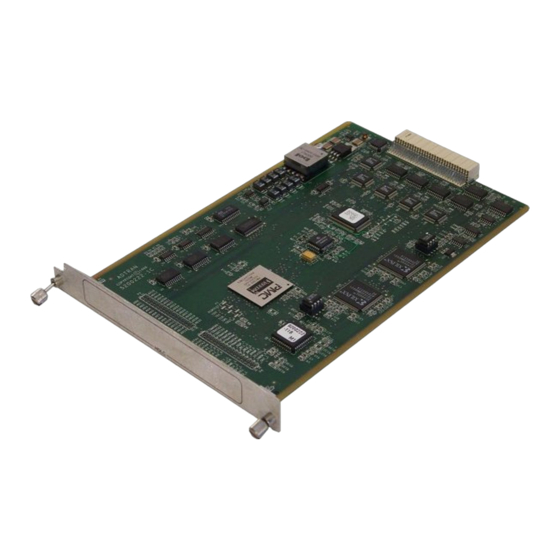
- Page 7 List of Figures Figure 1-1. ATLAS Private Frame Relay Application ................ 1-1 Figure 1-2. HDLC Module ........................1-5 Figure 2-1. Installing the HDLC Module ..................... 2-2 Figure 3-1. Modules Menu Tree for HDLC Module ................3-2 Figure 3-2. Modules Menu ........................3-2 Figure 3-3.
- Page 8 List of Figures and Tables viii HDLC Module User Manual 61200222L1-1...
-
Page 9: Chapter 1 Introduction
Introduction Chapter 1 WHAT IS HDLC? HDLC (High-Level Data Link Control) is a synchronous, bit-oriented data link control protocol that is used extensively in wide-area networks. Because of its popularity, HDLC has been the basis for a number of other protocols including LAPD (ISDN), PPP, and Frame Relay. -
Page 10: Hdlc Module - When Is It Needed
Chapter 1. Introduction HDLC MODULE - WHEN IS IT NEEDED? The HDLC Module is required for ATLAS applications requiring a large HDLC Controllers ( number of the HDLC Module includes 128 HDLC Con- trollers). As a resource module for the ATLAS system, the HDLC Module has no external physical interfaces. -
Page 11: Atlas Support Of Hdlc Controllers
Chapter 1. Introduction ATLAS SUPPORT OF HDLC CONTROLLERS ATLAS allocates HDLC Controllers to meet the user-application require- ments without user intervention. Table 1-1 describes ATLAS hardware components that include HDLC controllers. Table 1-1. ATLAS Components and Integrated HDLC Controllers Component Controllers Description ATLAS 800 Base Unit... -
Page 12: Hdlc Module Functional Description
Chapter 1. Introduction This situation requires 24 HDLC Controllers and, therefore, requires the HDLC Module. 3. T3 Transporting One or More PRI Circuits When a T3 circuit is transporting one or more PRI circuits, the HDLC Module is required to process the PRIs' D Channels. Two general-purpose HDLC Controllers can terminate a PRI from PLUS the T3 as needed, if you are using the ATLAS800... -
Page 13: Chapter 2 Installation
Carefully inspect the HDLC Module for shipping damages. If damage is suspected, file a claim immediately with the carrier and then contact ADTRAN Technical Support. If possible, keep the original shipping con- tainer for use in returning the HDLC Module for repair or for verification of shipping damage. -
Page 14: Power-Up And Initialization
Any self-test failures display in the terminal menu self-test log. WARRANTY AND CUSTOMER SERVICE ADTRAN will replace or repair this product within five years from the date of shipment if the product does not meet its published specification, or if it fails while in service. For detailed warranty, repair, and return... -
Page 15: Chapter 3 Operation
Operation Chapter 3 OVERVIEW The HDLC Module menus can be viewed from two sources, as shown in Table 3-1. The ATLAS User Manual provides detailed instructions on operating each of the supported management approaches. The remain- der of this chapter describes the menu items available for managing the HDLC Module using the terminal menu. -
Page 16: Menu Access
Chapter 3. Operation Type Part Number Menu Info Serial Number Alarms Board Revision Modules Test State Status Status DS0s Available Channel ID Channels DS0s Used DS0 Rate TX Frames Total Errors RX Frames CRC Errors Error Counters Aborted Frames Clear Counters Invalid Frames Figure 3-1. -
Page 17: Slt
Chapter 3. Operation > Write security: 3; Read security: 5 (Slot) Displays the number of available slots in the ATLAS chassis. Slot 0 refers to the ATLAS Base Unit. TYPE > Write security: 3; Read security: 5 Displays the module type currently installed in the slot or the module type you plan to install in the slot. -
Page 18: Status
Chapter 3. Operation Only if S reads O , can ATLAS use an installed module’s TATE NLINE resources. STATUS > Read security: 5 Displays status information on the following: Online The module is enabled and is responding to the System Controller’s status polls. -
Page 19: Info Menu
Chapter 3. Operation Figure 3-3. Menus Panel INFO MENU > Read security: 5 (Information) Displays information about the HDLC Module (see Figure 3-4). Figure 3-4. Info Menu » Part Number Displays the part number of the HDLC Module. » Serial Number Displays the serial number of the HDLC Module. -
Page 20: Channels
Chapter 3. Operation Figure 3-5. Status Submenu » Channels Read security: 5 Displays status information about the resources that have been allocated on the HDLC Module (see Figure 3-6). Figure 3-6. Channels Submenu »» Channel ID Indicates the resource number of the allocated resource listed. If a num- ber does not appear in the list, that resource is not currently allocated. -
Page 21: Error Counters
Chapter 3. Operation Displays the total number of errors received by the resource. Press »» Error Counters Enter on this field to view the number of T , CRC E OTAL RRORS RRORS , and I (Clear Counters) BORTED RAMES NVALID RAMES clears this menu item. - Page 22 Chapter 3. Operation HDLC Module User Manual 61200222L1-1...
-
Page 23: Index
Index aborted frames 3-7 hardware revision, locating 3-4 aborted frames errors 1-4 HDLC accessing the menus 3-2 menus 3-1 alarms menu 3-3 See Modules menu ATLAS features 3-7 module ATLAS system controller 3-2 features 1-4 functional description 1-4 installation procedure 2-1 installation, general information 1-4 bandwidth management methods 3-1... - Page 24 Index See also status submenu rev (revision) 3-4 serial number, locating 3-5 slt (slot) 3-3 service 2-2 state 3-3 shipping status 3-4 contents 2-1 See also status menu damage 2-1 test 3-3 slot 0 3-3 type 3-3 slt (slot) menu 3-3 moving through the menus 3-2 specifying module type 3-3 state menu 3-3...
- Page 25 (888) 4ADTRAN Repair and Return If ADTRAN Technical Support determines that a repair is needed, Technical Support will coordinate with the Customer and Product Service (CAPS) department to issue an RMA number. For information regarding equipment currently in house or possible fees associated...
Need help?
Do you have a question about the 1200222L1 and is the answer not in the manual?
Questions and answers