
Subscribe to Our Youtube Channel
Related Manuals for Maxcess Fife TruWide SE-45 Series


Summary of Contents for Maxcess Fife TruWide SE-45 Series
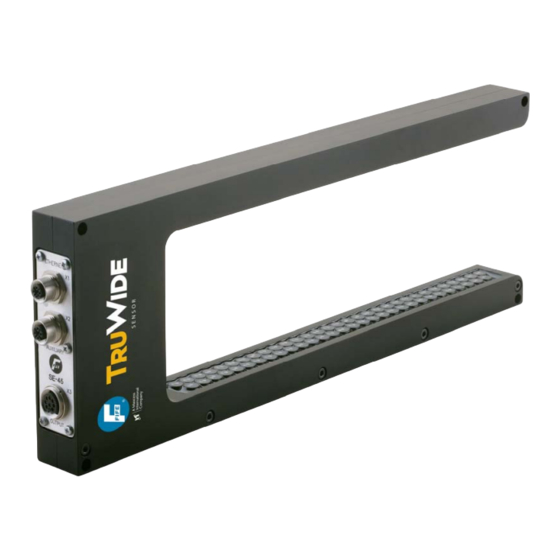
- Page 1 SE- 45 TRUWIDE ULTRASONIC SENSOR USER MANUAL SE-45 ULTRASONIC SENSOR (SE-45-52-10 Shown) 5/19/2009 © 2009 Fife Corporation. All rights reserved. Figure Sheet 1-903-A...
- Page 2 This page is intentionally blank. 5/19/2009 © 2009 Fife Corporation. All rights reserved. Figure Sheet 1-903-A...
-
Page 3: Copyright
SE-45 TRUWIDE ULTRASONIC SENSOR USER MANUAL COPYRIGHT COPYRIGHT All of the information herein is the exclusive proprietary property of Fife Corporation, and is disclosed with the understanding that it will be retained in confidence and will be used only for the purpose intended. Any reproduction of this User Manual, in any form, in whole or in part, requires the prior written consent of Fife Corporation. - Page 4 This page is intentionally blank. 5/19/2009 Page Figure Sheet 1-903-A...
-
Page 5: Table Of Contents
SE-45 TRUWIDE ULTRASONIC SENSOR USER MANUAL TABLE OF CONTENTS COPYRIGHT..............................i TABLE OF CONTENTS ..........................iii GENERAL INTRODUCTION ........................1 DEFINITION OF TERMS ......................... 1 SE-45 TRUWIDE ULTRASONIC SENSOR GENERAL INFORMATION ........2 CAUTIONS AND WARNINGS ......................2 GETTING STARTED ............................ 3 CONNECTIONS, SE-45 SENSOR .................... - Page 6 SE-45 TRUWIDE ULTRASONIC SENSOR USER MANUAL SW Number........................26 Distributed System ......................26 Configuration Menu Structure ................... 26 NETWORK............................. 27 TCP/IP..........................27 MAXNET ........................... 27 MAC-ID ..........................27 Network Menu Structure ....................27 SERVICE ............................28 MEASURING POINTS ...................... 28 Service Menu Structure ....................
-
Page 7: General Introduction
SE-45 TRUWIDE ULTRASONIC SENSOR USER MANUAL GENERAL INTRODUCTION DEFINITION OF TERMS 1. Controller/Processor – The electronics processing unit that controls and drives the actuators that are attached to it, in response to position feedback from the sensors. 2. MAC Address – (Media Access Control). This is the factory assigned hardware address of a SE-45 Sensor. -
Page 8: Se-45 Truwide Ultrasonic Sensor General Information
SE-45 TRUWIDE ULTRASONIC SENSOR USER MANUAL SE-45 TRUWIDE ULTRASONIC SENSOR GENERAL INFORMATION The instructions contained in this User Manual are written to support operation of the SE-45 TruWide Ultrasonic Sensor. Additionally, where applicable, instructions are included for communications with Fife Controllers/Processors, such as the Fife D-MAX Web Guide Controller. -
Page 9: Getting Started
SE-45 TRUWIDE ULTRASONIC SENSOR USER MANUAL GETTING STARTED CONNECTIONS, SE-45 SENSOR X1 – ETHERNET ETHERNET NETWORK CONNECTION. X2 – AUXILIARY AUXILIARY POWER (+10.5 TO +51 VDC). ANALOG OUTPUT (WEB WIDTH). X3 – OUTPUT CONNECTION TO CONTROLLER (DEFAULT). POWER INPUT (+10.5 TO +13.2 VDC). ANALOG OUTPUTS (EDGE1, EDGE2, WEB WIDTH). -
Page 10: Network Connection
SE-45 TRUWIDE ULTRASONIC SENSOR USER MANUAL NETWORK CONNECTION Optional Network Communication Settings in the SE-45 TruWide Sensor; 1. The IP Address of each Ethernet Device in a network must be unique to each Device in the network. All SE-45 Sensors are shipped from the factory with the same IP Address (10.0.0.150). If it is necessary to change the IP Address of the SE-45 Sensor, see “Network”... -
Page 11: Sensor Operation
SE-45 TRUWIDE ULTRASONIC SENSOR USER MANUAL SENSOR OPERATION SE-45 BASIC OPERATION The SE-45 TruWide Ultrasonic Sensor utilizes scanning technology to detect on-web and off-web transition edges of web material that is located within the sensor’s field of view. This allows new edges to be detected at any time. -
Page 12: Operation Modes
SE-45 TRUWIDE ULTRASONIC SENSOR USER MANUAL parameters. Recalling a Job immediately activates the position and proportional bands for all Virtual Sensors. The sensor default has only a single Job enabled and is configured as a Single Proportional Band, which is described below. In order to use more than one Job it must first be enabled in the “Job Enable”... -
Page 13: Se-45 Multiple Proportional Band Mode Of Operation
SE-45 TRUWIDE ULTRASONIC SENSOR USER MANUAL SE-45 Multiple Proportional Band Mode Of Operation The Multiple Proportional Band operation mode of the SE-45 TruWide Ultrasonic Sensor requires an Ethernet connection to a network device, such as a PC or a Fife D-MAX Operator Interface for configuration of the sensor. -
Page 14: Modbus/Tcp Interface
SE-45 TRUWIDE ULTRASONIC SENSOR USER MANUAL MODBUS/TCP INTERFACE The SE-45 Tru-Wide™ Sensor provides Modbus/TCP slave capability. (An optional Ethernet cable is required for communication between the sensor and a network device). The default settings permit the collection of lateral position information for up to 8 webs (16 edges). The default SE-45 configuration also supports remote control commands for Virtual Sensor operations such as learning edge positions and shifting Virtual Sensors individually or in groups. -
Page 15: Default Data
SE-45 TRUWIDE ULTRASONIC SENSOR USER MANUAL Default Data The default data available from SE-45 Modbus slave is as follows: SE-45 to Customer (57 words) Register Parameter Description Reserved Reserved. RemReqCmd Remote control command. (See remote control) RemReqStatus Remote control status. (See remote control) RemReqParam1 Remote control parameter. -
Page 16: Remote Control
SE-45 TRUWIDE ULTRASONIC SENSOR USER MANUAL Customer to SE-45 (4 words) Register Parameter Description Command Remote control command. Parameter1 New position (for absolute or relative shifting) Parameter2 Mask indicating which virtual sensors are included (if applicable) Parameter3 Shift speed (for shifting operations) Remote Control Issuing commands via Modbus/TCP can control various aspects of the sensor operation. - Page 17 SE-45 TRUWIDE ULTRASONIC SENSOR USER MANUAL Cancel any pending operation. This command can also be used to Cancel 0x1000 “ping” the sensor to verify its presence. Command Syntax: UNIT Parameter1 Not used. Parameter2 Not used. Parameter3 Not used. Response: RemReqCmd Duplicates the supplied command.
- Page 18 SE-45 TRUWIDE ULTRASONIC SENSOR USER MANUAL Move VS 0x4xxx Move virtual sensor to an absolute position. Absolute Command Syntax: UNIT Parameter1 Required Positive value indicating the desired virtual sensor position. It is interpreted according to the UNIT field described below. Parameter2 Optional Parameter used when LNK = 1 to move one or more virtual sensors when...
- Page 19 SE-45 TRUWIDE ULTRASONIC SENSOR USER MANUAL Move VS 0x5xxx Move virtual sensor relative to its current position. Relative Command Syntax: UNIT Parameter1 Required Signed value indicating the desired distance and direction to move the specified virtual sensor. It is interpreted according to the UNIT field described below.
- Page 20 SE-45 TRUWIDE ULTRASONIC SENSOR USER MANUAL Build a virtual sensor centered on each edge located in the sensor. Learn 0x6000 The virtual sensor numbers are assigned sequentially from the Edges closed end of the sensor to the open end. Command Syntax: UNIT Parameter1 Not used...
-
Page 21: Se-45 Web Page
SE-45 TRUWIDE ULTRASONIC SENSOR USER MANUAL SE-45 WEB PAGE The SE-45 TruWide Ultrasonic Sensor contains an integrated HTTP server that provides web page access to the sensor’s configuration parameters. This requires an optional Ethernet cable connected to a network device such as a PC, which contains a Web Browser. To communicate with the SE-45 Sensor, the PC and the Web Browser must be configured to match the SE-45 Sensor’s network settings. - Page 22 SE-45 TRUWIDE ULTRASONIC SENSOR USER MANUAL The parameters of the Analog Channels that can be edited, are as follows; Signal Source – The source of the signal that controls the Analog Outputs via the Analog Channels. (The source can be configured for each of the three Analog Channels, and for each Job, independently).
-
Page 23: Operator Interface
SE-45 TRUWIDE ULTRASONIC SENSOR USER MANUAL OPERATOR INTERFACE Note: The information and procedures in this section assume the use of an optional Ethernet cable, connecting the SE-45 TruWide Ultrasonic Sensor to a D-MAX Operator Interface. SE-45 HOME SCREEN 10/8 SE-45.SENSOR SE-45 JOB1 (Device Home Screen Shown) -
Page 24: Key Definitions
SE-45 TRUWIDE ULTRASONIC SENSOR USER MANUAL KEY DEFINITIONS A. Screen Select Key. This key is used to scroll through the devices that exist on the network. If the key is held for at least two seconds, a list of the devices is displayed. B. - Page 25 SE-45 TRUWIDE ULTRASONIC SENSOR USER MANUAL L. Left Arrow Key. In the Menu Levels, this key is used to enable/disable entries in the displayed list and also to move the cursor when editing values. M. Right Arrow Key. In the Menu Levels, this key is used to enable/disable entries in the displayed list and also to move the cursor when editing values.
- Page 26 SE-45 TRUWIDE ULTRASONIC SENSOR USER MANUAL This page is intentionally blank. 5/19/2009 Page Figure Sheet 1-903-A...
-
Page 27: Menus
SE-45 TRUWIDE ULTRASONIC SENSOR USER MANUAL MENUS Note: The information and procedures in this section assume the use of an optional Ethernet cable, connecting the SE-45 TruWide Sensor to a network device, such as the D-MAX Operator Interface. MENU NAVIGATION NOTES 1. -
Page 28: Job Settings Menu Structure
SE-45 TRUWIDE ULTRASONIC SENSOR USER MANUAL Setting the Proportional Band Size establishes the width of the Virtual Sensors. This is a global setting that applies to all Virtual Sensors. Sensor Linking provides a means to link two or more Virtual Sensors together. Then, if one of the Virtual Sensors is shifted, all of the Virtual Sensors that are linked to that Virtual Sensor will follow it as it shifts. -
Page 29: Select Job
SE-45 TRUWIDE ULTRASONIC SENSOR USER MANUAL SELECT JOB To enter the Select Job Menus, follow the “Select Job Menu Structure”, shown below. These menus may be used to select the desired job. (If the desired job is not listed, see “Job Enable” in the “Control Options” menus). -
Page 30: Hardware Settings
SE-45 TRUWIDE ULTRASONIC SENSOR USER MANUAL HARDWARE SETTINGS To enter the Hardware Settings Menus, follow the “Hardware Settings Menu Structure”, shown below. These menus may be used to calibrate the SE-45 Sensor. Use the up and down arrow keys to scroll through the list of items in a menu level. -
Page 31: Control Options
SE-45 TRUWIDE ULTRASONIC SENSOR USER MANUAL CONTROL OPTIONS To view or modify any of the following Control Options, follow the “Control Options Menu Structure”, shown below. Use the up and down arrow keys to scroll through the list of items in a menu level. Press the ENTER key to advance to the next menu level, or press the ESC key to revert back to the previous menu level. -
Page 32: Configuration
SE-45 TRUWIDE ULTRASONIC SENSOR USER MANUAL CONFIGURATION To view or modify any of the Configuration Settings, follow the “Configuration Menu Structure”, shown below. Use the up and down arrow keys to scroll through the list of items in a menu level. Press the ENTER key to advance to the next menu level, or press the ESC key to revert back to the previous menu level. -
Page 33: Network
SE-45 TRUWIDE ULTRASONIC SENSOR USER MANUAL NETWORK To view or modify any of the SE-45 Sensor Network Settings, follow the “Network Menu Structure”, shown below. Use the up and down arrow keys to scroll through the list of items in a menu level. Press the ENTER key to advance to the next menu level, or press the ESC key to revert back to the previous menu level. -
Page 34: Service
SE-45 TRUWIDE ULTRASONIC SENSOR USER MANUAL SERVICE To view any of the Service Menus, follow the “Service Menu Structure”, shown below. Use the up and down arrow keys to scroll through the list of items in a menu level. Press the ENTER key to advance to the next menu level. - Page 35 SE-45 TRUWIDE ULTRASONIC SENSOR USER MANUAL (Continued from previous page) 1X.9.1.2 Power 1X.9.1.2.1 Input Voltage (Input Voltage is displayed). 1X.9.1.2.2 Temperature A [°C] (Internal Temperature A is displayed). 1X.9.1.2.3 Temperature B [°C] (Internal Temperature B is displayed). 1X.9.1.2.4 (-6V Supply value is displayed). 1X.9.1.2.5 (+6V Supply value is displayed).
- Page 36 SE-45 TRUWIDE ULTRASONIC SENSOR USER MANUAL This page is intentionally blank. 5/19/2009 Page Figure Sheet 1-903-A...
-
Page 37: Specific Procedures
SE-45 TRUWIDE ULTRASONIC SENSOR USER MANUAL SPECIFIC PROCEDURES JOG VIRTUAL SENSORS If “Multiple Proportional Band” is selected in the “Job Settings”, “Set Sensor Mode” menu, then “Jog” will be displayed on the SE-45 Home Screen, adjacent to the “F5” key. This allows the operator to shift the position of selected Virtual Sensors. -
Page 38: Application Filtering
SE-45 TRUWIDE ULTRASONIC SENSOR USER MANUAL APPLICATION FILTERING Overview If desired, the SE-45 Sensor may be configured so that a D-MAX Operator Interface (OI) will be denied communication with the SE-45 Sensor. (This may be desired so that unauthorized personnel do not have access to the internal settings of the SE-45 Sensor). - Page 39 SE-45 TRUWIDE ULTRASONIC SENSOR USER MANUAL The next step is to configure the Operator Interface unit/s that will be communicating with the above, configured SE-45 Sensor/s by performing the appropriate following procedure. 1. If it is desired to “hide” the SE-45 Sensor/s so that they do not show up in the List Of Devices on the Operator Interface, perform the following procedure.
-
Page 40: Assigning Names For "All Applications" Filtering
SE-45 TRUWIDE ULTRASONIC SENSOR USER MANUAL Assigning Names For “All Applications” Filtering If desired, the names of the SE-45 Sensors may be assigned. 1. Once filtering is properly setup and enabled, the items in the List of Devices are formatted as follows: Application ID;... -
Page 41: System Notes
SE-45 TRUWIDE ULTRASONIC SENSOR USER MANUAL SYSTEM NOTES 1. Disconnect power from the SE-45 Sensor before connecting or disconnecting any cables. 2. All cable connectors must be tightened sufficiently to provide the required connection for the cable shielding. 3. Job selection changes must be performed with the Controller/Processor in either Manual mode or Servo-Center mode, only. -
Page 42: Maintenance
SE-45 TRUWIDE ULTRASONIC SENSOR USER MANUAL MAINTENANCE The SE-45 TruWide Ultrasonic Sensor requires no scheduled maintenance. When Necessary, clean the surface of the transducers using a clean, water dampened cloth. If necessary, a mild soap solution may be used to dampen the cloth. DO NOT use chemical cleaners or solvents when cleaning the transducers, since those materials may cause damage to the transducers. -
Page 43: Specifications
SE-45 TRUWIDE ULTRASONIC SENSOR USER MANUAL SPECIFICATIONS GENERAL Input Voltage Range, - 12 - 48 VDC nominal at the X2 Connector 10.5 - 51 VDC min/max (Customer Supplied Power) Input Voltage Range, - 12 VDC nominal at the X3 Connector 10.5 –... -
Page 44: Inputs And Outputs
SE-45 TRUWIDE ULTRASONIC SENSOR USER MANUAL INPUTS AND OUTPUTS Communication Port Ethernet Based – 100 Mbps – Auto MDIX (Medium-Dependent Interface Crossover) Sensor Output (4) (2 connectors) - Maximum Output +20 mA Individually Programmable 0 to 10 mA (Default), 400 ohm load, Maximum 0 to 20 mA (Available), 125 ohm load, Maximum 4 to 20 mA (Available), 125 ohm load, Maximum CABLE RESTRICTIONS... -
Page 45: Certifications And Environmental Compatibility
SE-45 TRUWIDE ULTRASONIC SENSOR USER MANUAL CERTIFICATIONS AND ENVIRONMENTAL COMPATIBILITY Product Certification Protection Class, IP 50 5/19/2009 Page Figure Sheet 1-903-A... - Page 46 FIFE CORPORATION 222 W. Memorial Road, Oklahoma City, OK 73114-2317, USA / Post Office Box 26508, Oklahoma City, OK 73126-0508, USA Phone: 405.755.1600 / 800.639.3433 / Fax: 405.755.8425 / E-mail: fife@fife.com / Web: www.fife.com 5/19/2009 Page Figure Sheet 1-903-A...
Need help?
Do you have a question about the Fife TruWide SE-45 Series and is the answer not in the manual?
Questions and answers