Table of Contents
Advertisement
Quick Links
Fife-Tidland GmbH
GLOBAL WEB MANAGEMENT SOLUTION
guiding inspection slitting winding
Fifestraße 1 - 65779 Kelkheim - Deutschland
Siemensstraße 13-15 - 48683 Ahaus - Deutschland
Telefon: +49 - 6195 - 7002 - 0
Fax: +49 - 6195 - 7002 - 933
GB
SE-46
Operating Instructions
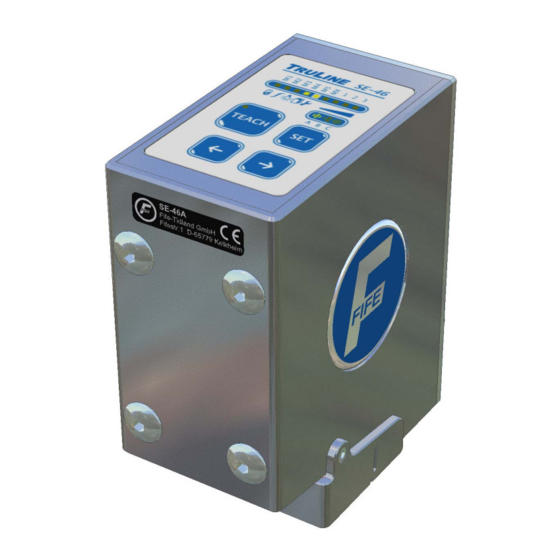
Digital Line Sensor
MI 1 1039 B
Advertisement
Table of Contents

Related Manuals for Maxcess Fife-Tidland SE-46


Summary of Contents for Maxcess Fife-Tidland SE-46
- Page 1 Fife-Tidland GmbH GLOBAL WEB MANAGEMENT SOLUTION guiding inspection slitting winding Fifestraße 1 - 65779 Kelkheim - Deutschland Siemensstraße 13-15 - 48683 Ahaus - Deutschland Telefon: +49 - 6195 - 7002 - 0 Fax: +49 - 6195 - 7002 - 933 SE-46 Operating Instructions Digital Line Sensor...
-
Page 2: Table Of Contents
CONTENTS INTRODUCTION About these operating instructions ........1-1 Proper use . - Page 3 CONTENTS User interface ............6-2 Keys and their functions .
- Page 4 CONTENTS TROUBLESHOOTING 11-1 Information ............11-1 Display possibilities .
-
Page 5: Introduction
INTRODUCTION 1 - 1 INTRODUCTION About these operating instructions These Operating Instructions describe the commissioning, operation and maintenance of the SE-46 digital line sensor and provide important instructions for proper use. These operating instructions are intended for both the system construction master as well as the operator who uses the SE-46 sensor in production. -
Page 6: Operating Principle
INTRODUCTION 1 - 2 Operating principle Active illumination (7) makes the material web brighter, which makes Information such as contrast transitions, lines or structures more visible. The SE-46 sensor samples this information with an imager (8) and compares it with an image line of the template saved during the calibration (reference). -
Page 7: Options
INTRODUCTION 1 - 3 45mm 1 Ambient light hood 6 Viewing direction 2 Marking of sensor center line 7 Material web 3 Marking of viewing area at a 8 Sensor field of view distance of 10mm 4 Marking of viewing direction A Distance from the viewing area to the target 5 Target light light... - Page 8 INTRODUCTION 1 - 4 Fife-Tidland GmbH offers additional types of illumination for other applications that cannot be detected with this standard lighting. Beginning with firmware version 004, the sensor can also be used for back light applications. A D-MAX operator interface is used for control The SE-46 sensor can also be set and calibrated with a D-MAX operator device.
-
Page 9: Safety Instructions
SAFETY INSTRUCTIONS 2 - 1 SAFETY INSTRUCTIONS Notes on using the SE-46 sensor Problem-free and reliable operation of the SE-46 sensor requires that the system be properly transported, stored, installed and placed in operation. Proper operation and careful maintenance will ensure a long service life for your sensor. -
Page 10: Symbols
SAFETY INSTRUCTIONS 2 - 2 Symbols Warning/caution - dangerous area Reference to general hazards that may result in bodily injuries or damage to the device Warning/caution - danger due to crushing Refers to danger of injury caused by crushing Warning/caution - danger due to cutting Refers to danger of injury caused by cutting Warning/caution - danger due to temporary blinding Refers to dangers that may be caused by being briefly... -
Page 11: Operation
SAFETY INSTRUCTIONS 2 - 3 The sensor must only be placed in operation if it has been securely mounted. Electrical connections on the sensor should always be made or disconnected while there is no electrical power in the system. Failure to observe this instruction may result in damage to the sensor. -
Page 12: Installation
INSTALLATION 3 - 1 INSTALLATION Transport and storage – The sensor must be protected against slipping during transport. – The sensor must be stored in a cool, clean, and dry place. – The sensor must not be stored close to strong magnetic fields. -
Page 13: Dimensions
INSTALLATION 3 - 2 Dimensions Fig 3.1 shows the dimensions of sensor SE-46. A Mounting holes D Viewing area B Material web E Sensor field of view C Recommended distance from the material web to the sensor Fig. 3.1: Dimensions of sensor SE-46 Installation location of sensor SE-46 –... - Page 14 INSTALLATION 3 - 3 – The material edge must be guided through a support roller in the sensor field of view so that there is no plane change (see 3.2). – The material web must run parallel to the lower edge of the sensor (see 3.3).
-
Page 15: Mechanical Fastening
INSTALLATION 3 - 4 Mechanical fastening To assist in mounting the SE-46 sensor, holes have been drilled in the housing (see A in 3.1). Together with various sensor bracket, this provides a wide range of installation options. Fig. 3.4: SE-46 mounted Assembly of the SE-46 with sensor bracket M Sensor bracket with distance adjustment Screw the micro-adjusting device (1) onto the SE-46... - Page 16 INSTALLATION 3 - 5 Sensor bracket M Sensor bracket MB " " M-20 25,5 MB-20 10,5 M-25 MB-25 M-32 27,5 MB-32 12,5 Fig. 3.6: Sensor bracket M and MB of the SE-46 Assembly of the SE-46 with sensor bracket MB Sensor bracket without distance adjustment Screw the adapter plate (2) onto the sensor with the M4x6 screws (5)
-
Page 17: Electrical Connection
INSTALLATION 3 - 6 Electrical connection CAUTION: Electrical connections on the sensor should always be made or disconnected while there is no electrical power in the system. Failure to observe this instruction may result in damage to the sensor. The sensor must be connected to the web guide controller as shown in the system diagram that appears in the system documentation. -
Page 18: Commissioning Of The Se-46 Sensor
COMMISSIONING OF THE SE-46 SENSOR 4 - 1 4 COMMISSIONING OF THE SE-46 SENSOR Sensor SE-46 The sensor can be placed in operation when – all assembly and connection tasks have been checked and – the SE-46 is in proper working condition. WARNING: There is a danger of cutting on the material web and a danger of crushing on the actuator if the web guide... - Page 19 COMMISSIONING OF THE SE-46 SENSOR 4 - 2 2. The sensor should be mounted at a distance of 10mm from the surface of the material web. This mechanical setting can optionally be checked with an adjustment tool. (see M5.1 Distance Gauge, page 7-9) 3.
-
Page 20: Commissioning Of Web Guide Controllers
COMMISSIONING OF WEB GUIDE CONTROLLERS 5 - 1 5 COMMISSIONING OF WEB GUIDE CONTROLLERS D-MAX Note: Fife-Tidland GmbH GLOBAL WEB MANAGEMENT SOLUTION guiding inspection slitting winding Fifestrasse 1 - 65779 Kelkheim - Germany Detailed information about sensor calibration is available in Siemensstrasse 13-15 - 48683 Ahaus - Germany Phone: +49 - 6195 - 7002 - 0 Fax: +49 - 6195 - 7002 - 933... - Page 21 COMMISSIONING OF WEB GUIDE CONTROLLERS 5 - 2 c. D-MAX operator interface (D-MAX OI): Press the F4 key to - select the job with y = 'J' if the SE-46 sensor is connected to input X5 or - select the job with y = 'K' if the SE-46 sensor is connected to input X9.
- Page 22 COMMISSIONING OF WEB GUIDE CONTROLLERS 5 - 3 1.3. Calibrating the locking signal on the D-MAX Depending on how the sensor is connected to the D-MAX Controller, perform the calibration for: – S 01 - Locking signal (menu 1y.5.1.1) if the SE-46 sensor is connected to input X5 or for –...
- Page 23 COMMISSIONING OF WEB GUIDE CONTROLLERS 5 - 4 d. Menu structure of controller (D-MAX OI): (2. Reference Value (Upper Limit)) Press the ENTER key ENTER e. Menu structure of controller (D-MAX OI): Press the ENTER key to save the calibration ENTER 1.4.
- Page 24 COMMISSIONING OF WEB GUIDE CONTROLLERS 5 - 5 c. Sensor keyboard: Press the Right Arrow key to select 10mA Menu structure of SE-46 sensor (D-MAX OI): Use the arrow keys to select a signal assignment of 10mA d. Menu structure of controller (D-MAX OI): (2.
-
Page 25: Setting The Asc (Automatic Sensor Control)
COMMISSIONING OF WEB GUIDE CONTROLLERS 5 - 6 2. Setting the ASC (Automatic Sensor Control) Note: Connection to X5: job with y = 'J' Connection to X9: job with y = 'K' 2.1. Setting ASC thresholds a. Menu structure of controller (D-MAX OI): Select menu 1y.3.y6.2 (Job Settings ASC Threshold 1 (Pos)) -
Page 26: Operation
COMMISSIONING OF WEB GUIDE CONTROLLERS 5 - 7 3.2. Setting the gain The gain must be set optimally. a. Menu structure of controller (D-MAX OI): Select menu 1.y.3.y3 (Job Settings Gain) Set the gain Operation Note: Depending on whether the sensor is connected to X5 or X9, operation on the D-MAX Controller in „Automatic”... - Page 27 COMMISSIONING OF WEB GUIDE CONTROLLERS 5 - 8 DP-20 Note: Fife-Tidland GmbH GLOBAL WEB MANAGEMENT SOLUTION guiding inspection slitting winding Fifestraße 1 - 65779 Kelkheim - Germany You can find detailed information about sensor calibration in Siemensstraße 13-15 - 48683 Ahaus - Germany Telephone: +49 - 6195 - 7002 - 0 Fax: +49 - 6195 - 7002 - 933 the "DP-20 Operating Instructions".
- Page 28 COMMISSIONING OF WEB GUIDE CONTROLLERS 5 - 9 Press the SET key. Menu structure of SE-46 sensor (D-MAX OI): Select menu xy.5.3 Simulate Analog Signals (Hardware Settings Simulate Analog Signales) Press the ENTER key ENTER Note: M5.3 Simulate Analog Signals, page 7-10 for additional information.
- Page 29 COMMISSIONING OF WEB GUIDE CONTROLLERS 5 - 10 Press the ENTER key d. Sensor keyboard: Press the Right Arrow key to select 10mA Menu structure of SE-46 sensor (D-MAX OI): Use the arrow keys to select a signal assignment of 10mA e.
- Page 30 COMMISSIONING OF WEB GUIDE CONTROLLERS 5 - 11 Menu structure of SE-46 sensor (D-MAX OI): Use the arrow keys to select a signal assignment of 0mA c. DP-20 web guide controller: Determine the first reference value Press the ENTER key d.
-
Page 31: Setting The Asc (Automatic Sensor Control)
COMMISSIONING OF WEB GUIDE CONTROLLERS 5 - 12 Menu structure of SE-46 sensor (D-MAX OI): Press and hold the ESC key until you reach the top level of the sensor 2. Setting the ASC (Automatic Sensor Control) 2.1. Selecting the ASC source a. -
Page 32: Operation
COMMISSIONING OF WEB GUIDE CONTROLLERS 5 - 13 3.2. Setting gain Gain must be set optimally. a. DP-20 web guide controller: Select menu 3D.1.1 (Manual Basic Gain) Set the gain Operation Note: The DP-20 web guide controller must be operated in „Automatic“... -
Page 33: Cdp-01
COMMISSIONING OF WEB GUIDE CONTROLLERS 5 - 14 CDP-01 Note: Detailed information about sensor calibration is available in the "CDP-01 Operating Instructions". "Supplementary CDP-01 Operating Manual Operating Instructions“ may also be available. If the system documentation includes "Supplementary Operating Instructions" for the CDP-01, follow the sequence described in that manual for commissioning the CDP-01. - Page 34 COMMISSIONING OF WEB GUIDE CONTROLLERS 5 - 15 Menu structure of SE-46 sensor (D-MAX OI): Select menu xy.5.3 Simulate Analog Signales (Hardware settings Simulate analog signals) Press the ENTER key ENTER Note: M5.3 Simulate Analog Signals, page 7-10 for additional information.
- Page 35 COMMISSIONING OF WEB GUIDE CONTROLLERS 5 - 16 Menu structure of SE-46 sensor (D-MAX OI): Use the arrow keys to select a signal assignment of 10mA f. CDP-01 web guide controller: Press the F2 key (5) to determine the second reference value g.
-
Page 36: Setting The Asc (Automatic Sensor Control)
COMMISSIONING OF WEB GUIDE CONTROLLERS 5 - 17 Menu structure of SE-46 sensor (D-MAX OI): Use the arrow keys to select a signal assignment of 10mA f. CDP-01 web guide controller: Press the F2 key (5) to determine the second reference value g. -
Page 37: Setting The Polarity And Gain
COMMISSIONING OF WEB GUIDE CONTROLLERS 5 - 18 c. CDP-01 web guide controller: Press the F1 key (4) to select the left ASC threshold d. CDP-01 web guide controller: Use the + or - key to set the left ASC threshold so that the first and second LED from the left on the LED bar are lit e. -
Page 38: Operation
COMMISSIONING OF WEB GUIDE CONTROLLERS 5 - 19 a. CDP-01 web guide controller: Continue pressing the Setup key (13) until LED 17 is lit b. CDP-01 web guide controller: Continue pressing the Sensor key (8) until LED 11 is lit Set the desired guiding direction Note: Additional information may be found in the section entitled... -
Page 39: Operation Via Sensor Keyboard
OPERATION VIA SENSOR KEYBOARD 6 - 1 OPERATION VIA SENSOR KEYBOARD Precondition Commissioning of the sensor must be performed as described in the relevant section of these Operating Instructions and must be completed successfully. Safety instructions While the sensor is in operation, the following safety instructions must be observed. -
Page 40: User Interface
OPERATION VIA SENSOR KEYBOARD 6 - 2 User interface Keys and their functions Fig. 6.1 shows the layout of the SE-46 sensor user interface. The sensor has four keys and two LED displays. Designation Function – Performs a calibration TEACH key –... - Page 41 OPERATION VIA SENSOR KEYBOARD 6 - 3 – During operation the LED display shows the currently detected position of the reference if the calibration was valid (the picture on the side shows an example of this) or lock information. The designations and symbols in the display have no meaning for this function.
-
Page 42: Se-46 Operation States
OPERATION VIA SENSOR KEYBOARD 6 - 4 web during operation - corresponds to what appears in the LED display The distance between the target light and the viewing area is 45mm (see also A in Fig. 1.2, page 1-3). SE-46 operation states Three operation states must be distinguished when the SE-46 is in operation: Calibration valid - reference detected... -
Page 43: Scan Frequency
OPERATION VIA SENSOR KEYBOARD 6 - 5 to the reference are encountered, as this could have a negative result on material guiding. If multicoloured patterns are used as a reference, note that drifting of the individual colours may occur during the printing process. -
Page 44: Sensor Mode
OPERATION VIA SENSOR KEYBOARD 6 - 6 insufficient, a lower setting of the scan frequency must be selected. High settings of the scan frequency cannot be used with unambiguous scanning conditions (for example strong contrast, no possibility of confusion). A diagram in Appendix B (see 14-1) provides help for making the setting of the scan frequency. -
Page 45: Calibration Of The Se-46
OPERATION VIA SENSOR KEYBOARD 6 - 7 Calibration of the SE-46 Setting the scan frequency see menu M2 Scan Frequency, page 7-3 Press the TEACH key to start the calibration process If a valid calibration is already active, hold the TEACH key down for 2 seconds. -
Page 46: Enhanced Functionality
OPERATION VIA SENSOR KEYBOARD 6 - 8 Enhanced functionality Deviation Tolerance The deviation tolerance of the SE-46 sensor indicates the degree to which the current information in the sensor field of view must match the calibrated reference in order to generate a valid sensor signal (see also menu M1 Deviation Tolerance, page... -
Page 47: Interrupted Reference
OPERATION VIA SENSOR KEYBOARD 6 - 9 Interrupted reference Generally there is no limit for the ratio between the length of the reference and the length of the interruption. The reference must contain at least the minimum length depending on the scan frequency setting. Please note, however, that if the position mark is lost, the sensor may respond to similar patterns in the printed image, thereby destabilising control. -
Page 48: Parameter Setting Via Sensor Keyboard
PARAMETER SETTING VIA SENSOR KEYBOARD 7 - 1 PARAMETER SETTING VIA SENSOR KEYBOARD Notes This section describes how to set the parameters of the SE-46 using the keyboard on the sensor. All parameters can also be set by an optional D-MAX OI (Operator Interface) (see Section The D-MAX operator interface is used for control, page... -
Page 49: M1 Deviation Tolerance
PARAMETER SETTING VIA SENSOR KEYBOARD 7 - 2 M1 Deviation Tolerance Description The Deviation Tolerance parameter of the SE-46 indicates how completely the current information in the sensor field of view must agree with the calibrated reference to generate a valid sensor signal (see also Deviation Tolerance, page 6-8). -
Page 50: M2 Scan Frequency
PARAMETER SETTING VIA SENSOR KEYBOARD 7 - 3 M2 Scan Frequency Description The Scan Frequency parameter is used to define a time window for determining a valid position value (see also Scan frequency, page 6-5). Scan frequency diagram: The scan frequency diagram is used to facilitate selection of the optimum setting (see Appendix B Page 14-1). - Page 51 PARAMETER SETTING VIA SENSOR KEYBOARD 7 - 4 Input Reduce or increase the scan frequency with the arrow keys Save the entry with the TEACH key Press the SET key for 2seconds to cancel 26.01.09 SE-46 MI 1 1039 B...
-
Page 52: M3 Type Of Illumination
PARAMETER SETTING VIA SENSOR KEYBOARD 7 - 5 M3 Type of Illumination Description The Type of Illumination parameter can be used to select between standard illumination (RGB) and other types of illumination. Menu Key sequence for menu: Press and hold until LED M1 is flashing Press repeatedly until LED M3 is flashing Press, LED M3 is lit The LED of the current setting for the Type of Illumination... -
Page 53: M4 Active Profile
PARAMETER SETTING VIA SENSOR KEYBOARD 7 - 6 M4 Active Profile Description This parameter is used to select the active profile. The settings of a continually recurring reference can thus be used again without having to perform an additional calibration. The sensor permits a selection from 3 fixed and 2 additional profiles. - Page 54 PARAMETER SETTING VIA SENSOR KEYBOARD 7 - 7 Active Profile Optional Optional Input Select the desired profile with the arrow keys Save the entry with the TEACH key Press the SET key for 2seconds to cancel MI 1 1039 B SE-46 26.01.09...
-
Page 55: M5 Hardware Settings
PARAMETER SETTING VIA SENSOR KEYBOARD 7 - 8 M5 Hardware Settings The hardware settings are used – to adjust the sensor mechanically and – to adjust the web guide controller used in the system to the analog signals of the sensor The following menus are available for hardware settings: –... -
Page 56: M5.1 Distance Gauge
PARAMETER SETTING VIA SENSOR KEYBOARD 7 - 9 M5.1 Distance Gauge Description The Distance Gauge menu is used to adjust the distance between the sensor and material web during the mechanical adjustment of sensor SE-46. A strong contrast is required for the template. A black line on white paper is optimal for this purpose. -
Page 57: M5.3 Simulate Analog Signals
PARAMETER SETTING VIA SENSOR KEYBOARD 7 - 10 M5.3 Simulate Analog Signals Description If a web guide controller processes the analog guiding signals of the sensor, the web guide controller must be checked and adjusted if necessary during commissioning or after a component is replaced (SE-46, cable or web guide controller). - Page 58 PARAMETER SETTING VIA SENSOR KEYBOARD 7 - 11 Press the ’Right-Arrow’ key LEDs 1, 2 and 3 flash. Sensor SE-46 sends 10mA to both signal outputs. The calibration of analog signal inputs must be performed according to the information about the relevant web guide controller in Section Commissioning of the SE-46...
-
Page 59: Mx Menus
PARAMETER SETTING VIA SENSOR KEYBOARD 7 - 12 MX menus The following menus are available for additional settings: – MX.1 - Active Field of View – MX.2 - Profile Switching activated? 26.01.09 SE-46 MI 1 1039 B... -
Page 60: Mx.1 - Active Field Of View
PARAMETER SETTING VIA SENSOR KEYBOARD 7 - 13 MX.1 - Active Field of View Note: The menu is present starting at firmware number ... - 004. Description The parameter for Active Field of View is used to set the range in which the sensor should recognise the reference. - Page 61 PARAMETER SETTING VIA SENSOR KEYBOARD 7 - 14 Save the entry with the TEACH key Press the SET key for 2seconds to cancel 26.01.09 SE-46 MI 1 1039 B...
-
Page 62: Mx.2 - Profile Switching Activated
PARAMETER SETTING VIA SENSOR KEYBOARD 7 - 15 MX.2 - Profile Switching activated ? Note: The menu is present starting at firmware number ... - 004. Description The parameter Profile Switching activated ? is used to define whether the sensor will use a fallback profile if the reference of the currently used profile is lost. - Page 63 PARAMETER SETTING VIA SENSOR KEYBOARD 7 - 16 Input Select the desired setting with the arrow keys Save the entry with the TEACH key Press the SET key for 2seconds to cancel 26.01.09 SE-46 MI 1 1039 B...
-
Page 64: The D-Max Operator Interface Is Used For Control
THE D-MAX OPERATOR INTERFACE IS USED FOR CONTROL 8 - 1 THE D-MAX OPERATOR INTERFACE IS USED FOR CONTROL Notes This section describes only the operation of the SE-46 via a D-MAX operator interface. Note: The following section is a supplementary description of the D-MAX operator interface containing information about how to set up the SE-46 sensor via the D-MAX operator interface. -
Page 65: Top Level
THE D-MAX OPERATOR INTERFACE IS USED FOR CONTROL 8 - 2 Top level All control functions required for normal operation of the SE-46 sensor are available on the top level of the D-MAX operator interface: A Selection of "devices" B Teach key E Select profile G Deviation tolerance menu (see Page... -
Page 66: D-Max Menu Of The Se-46
THE D-MAX OPERATOR INTERFACE IS USED FOR CONTROL 8 - 3 D-MAX menu of the SE-46 Note: Information about how to operate the menus of the D-MAX operator interface may be found in the "D-MAX" operating instructions. Menu structure Section Appendix C - Menu structure of D-MAX, page 15-1 contains an overview of all menus of the D-MAX operator interface related to the SE-46 sensor. -
Page 67: Application Examples
APPLICATION EXAMPLES 9 - 1 9 APPLICATION EXAMPLES Edges of printed images For example, the edge of a printed image might be the outer edge of a printed image or a striking longitudinal colour contrast. The edge of a printed image should be calibrated with sensor mode 'B - Edge mode'. -
Page 68: Guiding Lines
APPLICATION EXAMPLES 9 - 2 After sections without a position signal (6), the sensor is sensitive to other edges of printed images (7). When the edge of printed image is offset in the field of view, the sensor recognises this contrast transition as valid, resulting in a guiding fault. -
Page 69: Complex Patterns As Guiding Lines
APPLICATION EXAMPLES 9 - 3 Fig 9.4 A Web running direction B Sensor field of view 1 Clean scanning of guiding line Guiding active 2 No position signal present Locking active 3 Clean scanning of guiding line Guiding active 4 Contrast transition deviates too much Locking active 5 Width of guiding line deviates Locking active... - Page 70 APPLICATION EXAMPLES 9 - 4 A pattern as the term is used here is an arrangement of lines and/or edges extending in the direction in which the web is running which provides a mark that cannot be confused because of the sequence of individual contrast transitions. The edge of a printed image should be calibrated with sensor mode 'C - Pattern mode'.
-
Page 71: Setting The Width Of The Reference Pattern
APPLICATION EXAMPLES 9 - 5 Setting the width of the reference pattern During the calibration process, the user can use the arrow keys to determine which area of the pattern will be saved in the sensor field of view as a reference. This setting indirectly affects the size of the offset range. - Page 72 APPLICATION EXAMPLES 9 - 6 – Otherwise only one of the two edges can be calibrated in sensor mode 'B - Edge mode'. A Web running direction B Sensor field of view 1 No print mark Locking active 2 Scanning of print mark Guiding active 3 No print mark Locking active...
-
Page 73: Maintenance
MAINTENANCE 10 - 1 MAINTENANCE Maintenance work The sensor's viewing window must not have any contamination on it. Therefore the viewing window must be cleaned at regular intervals with a neutral glass cleaner and a soft cloth. There are no other maintenance tasks to be performed for the SE-46 sensor. -
Page 74: Troubleshooting
TROUBLESHOOTING 11 - 1 TROUBLESHOOTING Information The SE-46 is capable of detecting errors that occur. If a D-MAX operator interface is present in the system, error messages can be viewed on the display of the D-MAX OI. Display possibilities The following displays must be checked when an error occurs: –... -
Page 75: Led Display On The Se-46
TROUBLESHOOTING 11 - 2 LED display on the SE-46 LED display Indicates Remedy Calibration invalid because Perform calibration – faulty or see also Calibration of the – calibration not performed SE-46, page 6-7 Reference not in the sensor field of view: Guiding locked Reference in the sensor field of view:... - Page 76 TROUBLESHOOTING 11 - 3 LED display Indicates Remedy No display present No power supply? Check the power supply Displays not listed in this table Is the sensor in a menu? Continue pressing the SET key until a normal operating display appears If that is not successful, please contact an employee of Fife-Tidland GmbH...
-
Page 77: Faults
TROUBLESHOOTING 11 - 4 Faults Fault Reason Remedy Restore the original light The ambient light has conditions or changed significantly Recalibrate the sensor Dirt on the sensor's field of see Section Maintenance, vision page 10-1 Lock ambient light hood in The sensor is recognising the place reference poorly or is no... -
Page 78: Problems When Calibrating The Reference
TROUBLESHOOTING 11 - 5 Problems when calibrating the reference Various problems may occur on the sensor during calibration to prevent calibration from being successfully performed. The sensor indicates this only through the operation state message "Calibration invalid". If there are problems with the calibration, check first whether the required reference is in the sensor field of view and whether the distance from the sensor to the material web is... -
Page 79: Problems With Guiding
TROUBLESHOOTING 11 - 6 Continue pressing the SET key until LEDs A, B and C in the display for the sensor mode are flashing simultaneously Press the Teach key The sensor is reset to the last valid calibration and switches back to normal operation. The target light points at the position of the reference if it is in the field of view. -
Page 80: Error Messages On The Optional D-Max Operator Interface
TROUBLESHOOTING 11 - 7 Error messages on the optional D-MAX operator interface The optional D-MAX operator interface is capable of recognising errors that occur and displaying them accordingly in operating mode "Calibration invalid". Error message when exiting a menu If the parameters for scan frequency or type of illumination are changed, the error message Parameters contradict profile appears in the display of the D-MAX operator interface. - Page 81 TROUBLESHOOTING 11 - 8 Message Reason Remedy The current scan frequency 3: Scan freq.setting Increase or reduce the scan setting is not suitable for unsuitable! frequency setting calibration. Check whether the scan frequency setting can be The time window of the scan reduced.
-
Page 82: Technical Data
TECHNICAL DATA 12 - 1 TECHNICAL DATA General information Housing ABS coated Covering window Glass Housing dimensions Length = 110mm Width = 65mm Height = 120mm Weight about 1000g Protection type According to DIN EN 60529: IP54 Ambient conditions 0°C - 60°C at max. 90% relative humidity, non-condensing 60°C up to 1000m altitude 50°C up to 3000m altitude Optical properties... -
Page 83: Electrical Connection
TECHNICAL DATA 12 - 2 Electrical connection X1 plug connector for Ethernet M12 socket, 4-pin, D-coded X1 plug assignment: Description Housing Shield X2 plug connector for power supply and analog outputs M12 plug, 5-pin, B-coded X2 plug assignment: Description Uv (+) Position signal Lock signal Detect... -
Page 84: Power Supply
TECHNICAL DATA 12 - 3 Power supply The system provided is optimised for the required application in terms of the electrical connection of the SE-46 sensor. Changes to this application may result in an alternative connection for the sensor and should therefore always be discussed with Fife-Tidland GmbH. -
Page 85: Appendix A - Menu Structure
APPENDIX A - MENU STRUCTURE 13 - 1 APPENDIX A - MENU STRUCTURE 26.01.09 SE-46 MI 1 1039 B... -
Page 86: Appendix B - Scan Frequency Diagram
APPENDIX B - SCAN FREQUENCY DIAGRAM 14 - 1 APPENDIX B - SCAN FREQUENCY DIAGRAM MI 1 1039 B SE-46 26.01.09... -
Page 87: Appendix C - Menu Structure Of D-Max
APPENDIX C - MENU STRUCTURE OF D-MAX 15 - 1 APPENDIX C - MENU STRUCTURE OF D-MAX „x“ - Sensor mode: 1 - Line mode A 2 - Edge mode B 3 - Pattern mode C „y“ - Selected profile (K, L, M, N or O) ENTER xy.3 Deviation Tolerance... -
Page 88: 16 Service
Deutschland Telefon: +49 - 6195 - 7002 - 0 Fax: +49 - 6195 - 7002 - 933 Web: www.maxcess.eu Fife-Tidland Ltd. Millennium House - Progress Way Denton/Manchester, M34 2GP - Great Britain Telefon: +44 - 161 - 320 - 2000...
Need help?
Do you have a question about the Fife-Tidland SE-46 and is the answer not in the manual?
Questions and answers