
Related Manuals for Maxcess FIFE DST-1


Summary of Contents for Maxcess FIFE DST-1
- Page 1 FIFE GUIDING SOLUTIONS DST-1 Web Guiding Sensor with Operator Interface User Manual MI 2-311 1 B...
-
Page 2: Table Of Contents
CONTENTS INTRODUCTION About these operating instructions ..............5 Product overview ..................... 6 Model number ....................6 Serial number....................6 DST-1 components ..................7 Ordering information ..................7 SAFETY Instructions for use ..................8 Symbols used ....................8 Basic safety information .................. 9 INSTALLATION Product dimensions .................. - Page 3 CONTENTS MANUAL SETUP PROCEDURE Manual setup procedure steps ..............39 SENSOR MAINTENANCE Backup and restore device settings ............... 40 9.1.1 Save device settings ................40 Device restore ....................41 9.2.1 Restore device settings ..............41 Firmware update ................... 42 Replacing DST-1 components ............... 43 9.4.1 Replacing the sensing element ............
- Page 4 CONTENTS FIGURES Figure 1. Component identification ..................7 Figure 2. Dimensions: DST-1 sensing element and operator interface ........ 11 Figure 3. Cable and USB connections ................... 11 Figure 4. Operator interface wall mount installation ............12 Figure 5. Operator interface panel mount installation ............13 Figure 6.
-
Page 5: 1.0 Introduction
About these operating instructions All of the information herein is the exclusive proprietary property of Maxcess International, and is disclosed with the understanding that it will be retained in confidence and will neither be duplicated nor copied in whole or in part nor be used for any purpose other than for which disclosed. -
Page 6: Product Overview
INTRODUCTION Product overview The DST-1web guiding sensor is a smart sensor product, packaged with a powerful and simple to use operator interface. The DST-1 sensing element is based on a wide angle, far- looking NIR (Near Infra-Red) digital image sensor. The web guiding sensor can drive two independent outputs, producing edge or line tracking signals, web center or web width, near edge or far edge, by processing up to four... -
Page 7: Dst-1 Components
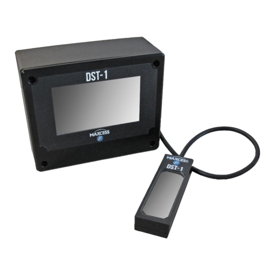
INTRODUCTION DST-1 components 1 - DST-1 Operator interface 2 - DST-1 Sensing element 3 - DST-1 Sensing element mounting bracket kit Figure 1. Component identification Ordering information Item Part number Drawing (reference) DST-1 Sensor (complete unit) 290007510 225799 DST-1 Operator interface 290007404 225698 DST-1 Sensing element... -
Page 8: 2.0 Safety
SAFETY INSTRUCTIONS 2.0 Safety Instructions for use To ensure safe and problem free installation of the DST-1, it must properly transported and stored, professionally installed and placed in operation. Proper operation and maintenance will ensure a long service life of the device. Only persons who are acquainted with the installation, commissioning, operation and maintenance of the system and who possess the necessary qualifications for their activities may work on the DST-1. -
Page 9: Basic Safety Information
Moving webs of material can produce large static voltage potentials. Protect against electric shocks by ensuring that the DST-1 is properly connected to a Maxcess web guiding controller and that the controller is properly grounded via the PE circuit of the building or machine. - Page 10 SAFETY INSTRUCTIONS Basic safety information continued WARNING – Death or injury can result from unexpected movement of the machine into which the DST-1 is installed. Protect against unexpected movement by removing electrical power from the DST-1 and the machine into which the DST-1 is being installed.
-
Page 11: 3.0 Installation
INSTALLATION 3.0 Installation Use shielded cable for all cables except for power cable. Product dimensions Units are in millimeters [inches] Figure 2. Dimensions: DST-1 sensing element and operator interface sensing element (a) USB port: DST-1 or memory stick (b) Power/signal cable Figure 3. -
Page 12: Mounting The Dst-1 Operator Interface
DST-1 sensing element with cable** Output cable assembly** Figure 4. Operator interface wall mount installation * These parts are available as a kit – Maxcess PN 290007415 ** Feed these two items through the wall mount adapter to the cable clearance cutouts. www.maxcessintl.com... -
Page 13: Panel Mount
Dog point set scr, M4 x 40, 4 each* DST-1 sensing element with cable** Output cable assembly** Figure 5. Operator interface panel mount installation * These parts are available as a kit – Maxcess PN 290009991 ** Feed these two items through the panel cutout www.maxcessintl.com DST-1... -
Page 14: Dst-1 Mounting Bracket Assembly
INSTALLATION 3.2.3 DST-1 mounting bracket assembly CAUTION – Never place electrical cables under mechanical strain. Always provide mechanical support of wiring with either clamps or flexible or rigid conduit. Description Part number Extrusion Custom length (see drawing 225774 for options) Mounting bracket 290007372 Flat hd cap scr, M5 x 8, 2 each... -
Page 15: Electrical
INSTALLATION Electrical 1. Connect the power/signal connector from the DST-1 to any Maxcess guide or D-MAX unit. When a guide is powered on, it will supply power for the DST-1 sensor. Wiring diagrams DST-1 Connector layout Operator interface pinout (viewed from the back side) -
Page 16: Analog Outputs
INSTALLATION Analog outputs 3.5.1 DST-1 Analog output 1 and 2 The outputs are designed to provide real-time control signal to a web guide system. They provide proportional response to detected web offset. Both of the outputs are formed by open-drain transistor pins and the Common Return signal. -
Page 17: Optical Sensor Installation
INSTALLATION Optical sensor installation When planning to install DST-1 sensor, please be aware the sensor’s large field of view and working distance. Any elements of machine frame in the view can potentially distract the sensor from the web guiding. Maximize the web view and minimize the presence of non- related elements to web guiding process. -
Page 18: Sensor Placement Guidelines
INSTALLATION 3.6.2 Sensor placement guidelines Dimensions are in mm [inches] (a) Main sensing element (b) Secondary sensing element Figure 10. DST-1 sensor optical center location (a) Sensing element (b) Web Figure 11. DST-1 recommended sensor to web distance All sensing elements face the 'web' in this illustration. A - Edge guiding B - Edge guiding C - Center guiding... -
Page 19: 4.0 Dst-1 Password Security
SECURITY 4.0 DST-1 Password Security Overview Password security settings allow administrators or privileged operators to protect selected functions from being changed or performed by personnel who do not have the authority. Definitions for the purpose of this chapter: Admin (or privileged operator) has a password and full access to all menus. -
Page 20: Set Up Password Security (First Time Use)
SECURITY Set up password security (first time use) ENABLE PASSWORD MAIN SCREEN > SETUP > ADMIN > PASSWORD to access the password options screen. Press ENABLE PASSWORD. User-selected buttons and default selections will remain highlighted until future changes are made. PASSWORD FOR... - Page 21 SECURITY SET PASSWORD 1. Press to set password; a number keypad or a keyboard will open, depending on the selected password type. 2. Enter a password. 1234 Save password entry; return to the password options screen. Cancel entry. 3. At the password options screen: Save all password settings and return to ADMIN menu.
-
Page 22: Identifying Security Status
SECURITY Identifying security status Admin is logged in; no security - Password protection is enabled but not activated. - No password required; all menus are accessible to all users. - Admin needs to log out to activate security. Security is activated. - Operators cannot access any function with a lock icon on its button. -
Page 23: Change Password Or Password Type
SECURITY Change password or password type MAIN SCREEN > SETUP > ADMIN > PASSWORD If the lock icon is present, enter password when prompted by the appearance of the login screen anywhere along the path. At the password options screen: Highlighted selections indicate the current password settings. -
Page 24: 5.0 Dst-1 Operator Interface Menu Structure
OI MENU STRUCTURE 5.0 DST-1 Operator interface menu structure Main screen (top level menu) JOBS Opens menu of saved jobs for selection. Can be password protected. SETUP Access sensor configuration settings and utilities. Can be password protected. Jobs selection menu Contains list of previously defined and saved configurations. - Page 25 OI MENU STRUCTURE Menu structure continued Service menu The Service menu contains the following group of utilities. VIEW SIGNALS Analog outputs monitor Troubleshoot device outputs and performance. TEST OUTPUTS Analog outputs You can manually modify each output to generate sine- wave and saw-tooth signals.
-
Page 26: 6.0 Sensor Operating Parameters
OPERATION 6.0 Sensor operating parameters To aid in understanding the device configuration procedure, this section presents the device structure, key parameters, their practical functions and graphical representation on the OI screen. DST-1 signal internal processing consists of three major system elements, illustrated in Figure 13: 1) Acquiring a web image 2) Processing it... -
Page 27: Global Parameter Group
0 to 10 mA, 0 to 20 mA, 4 to 20 mA Output 2 polarity Second output polarity toggle selection. Switches between incremental and decremental output behavior. Background Do not use unless recommended by Maxcess Technical Support. www.maxcessintl.com DST-1 MI 2-311 1 B... - Page 28 OPERATION Edge markers Main edge Visual aid toggle switch to enable or disable main edge detection point. Visible when edge is detected. ROI (Region of Interest) Visual aid toggle switch to enable or disable ROI presence Minor edge Visual aid toggle switch to enable or disable minor edge detection point.
-
Page 29: Manual Setup Parameters
Opaque, matte, non-gloss, non-glare Clear, reflective, glossy Gain Default: 16 Range: 16 to 63 Do not use unless recommended by Maxcess Technical Support. Depth Main backlight control parameter Default: 100 (for web distance 20 to 50 mm) Range: 0 to 1000* (*effective maximum) -
Page 30: Signal Function Types
OPERATION Signal function types As the camera sensing element feeds a web image to the signal block, it can be interpreted in a number of ways. To simplify the web image translation, the signal parameter defines this process. Camera Signal 1 Output (sensing (current) - Page 31 OPERATION Signal web processing parameters These parameters configure web image processing algorithms. They are unique for each signal. From the main screen, select SETUP > SETTINGS > JOB SETUP > MANUAL SETUP > OUTPUT 'N' > select tab S1 or S2. When a signal is enabled, its tab is bright.
-
Page 32: Edge/Line Detection Functions
OPERATION 6.4.1 Edge/Line detection functions Each function has an associated image and code name, for example, Fn. Press the icon four times to cycle through the options. Code Icon Description Web type Example Opaque web F1 function is always Opaque looking for the right edge Non-gloss in associated ROI. -
Page 33: Roi Definition And Configuration
OPERATION 6.4.2 ROI definition and configuration Region of Interest, or ROI, is a very important set of parameters for the web processing algorithms. ROI is an element of the communication link between the technician setting up the job and the sensor image processing methods. -
Page 34: Using Dst-1 Oi Touch Screen To Set Roi
OPERATION 6.4.3 Using DST-1 OI touch screen to set ROI Example 1. Defining ROI size. Use two fingers to re-size and watch for the maximum size limits. Example 2. Defining ROI position. Drag the ROI with your finger over web edge/line. If the Dynamic ROI setting is enabled, the horizontal position will be controlled by the configured edge location, and dragging the ROI... -
Page 35: Automatic Setup Procedure
OPERATION Automatic setup procedure Many opaque web materials use guiding settings that are simple enough for the sensor automatic setup procedure. The procedure is based on the following rules: 1) Auto-setup will overwrite the current job settings. If you wish to save the current job, enable and select a new job before running auto-setup. - Page 36 OPERATION Auto-setup continued There are four possible outcomes for auto-setup. Right edge guiding Left edge guiding Center guiding Web detection failed Press RESTART to run auto-setup again, if you wish. Save results. Cancel and return to previous screen. www.maxcessintl.com DST-1 MI 2-311 1 B Page 36 of 48...
-
Page 37: Figure 19. Signal Data And Manual Setup Flow Directions
OPERATION Manual setup procedure Manual setup is used for web materials with special properties or for setting a guide target at the specific place in a web. The manual setup procedure works in the opposite direction of the sensor data flow as described in the Sensor Operating Parameters chapter. -
Page 38: Table 2. Factory Default Job Configuration Settings
OPERATION Table 2. Factory default job configuration settings Parameter group 1 CAMERA Parameter name Default value Notes CLR/REFL WEB Default setting for Opaque web Gain Minimum Depth Value for a web distance 20 to 50 mm Brightness Minimum Parameter group 2 OUTPUT N Signal Function Output 1 - Signal 1... -
Page 39: Manual Setup Procedure Steps
OPERATION Manual setup procedure steps 1. Job selection Select a new job, if necessary. This step is optional. Go to Global Setup and press Enable Jobs. 2. Camera backlight Access the backlight settings. This is the first step in the process, since the underlying web detection functions all rely on well-lit web image. -
Page 40: Sensor Maintenance 9.1 Backup And Restore Device Settings
MAINTENANCE 9.0 Sensor maintenance Backup and restore device settings You can create up to five device restoration points in the device internal memory or to an external USB drive. Each of these restoration files saves all device settings, except for 1) the sensor pairing key and 2) password security settings. -
Page 41: Device Restore
MAINTENANCE Device restore You can restore device configuration settings from the device internal memory storage or from an external USB drive. When a USB memory stick is inserted, it takes precedence over the DST-1 internal memory. The display will show only the backup points created on the memory stick. -
Page 42: Firmware Update
MAINTENANCE Firmware update 1. Back up your device configuration. (See page 9.0.) 2. Shutting off the power to the OI is optional. Remove the sensing element from USB port located on the back side of the operator interface. 3. Plug in USB drive that holds the new firmware file(s). Confirm it by green USB memory icon on the OI screen. -
Page 43: Replacing Dst-1 Components
MAINTENANCE Replacing DST-1 components 9.4.1 Replacing the sensing element Note: Shutting off the power to the OI is optional. Remove the existing sensing element from USB port located on the back side of the operator interface. Plug the new sensing element into the USB port. Enter the pairing key code;... -
Page 44: 10.0 Device Recovery Options
10.0 Device recovery options Reset device configuration to default factory settings 1. Turn off power to the DST-1 unit. 2. Turn power back on — when the Maxcess logo appears, place and hold three fingers on the screen until the confirmation screen appears. -
Page 45: Troubleshooting 11.1 Fault Diagnostics And Rectification
Wrong web material type for Refer to the manual for the auto- Auto-setup setup conditions OI security access is denied Password mismatch Contact Maxcess technical support to re-set password OI display is dark OI power connection Check power/signal connection and re-connect... - Page 46 SPECIFICATIONS 12.0 Specifications General specifications OI display type Color, touchscreen, 480 x 272 px OI connection type USB 2.0 Sensor working spectrum NIR (Near Infrared) Operating temperature range °C [°F] 0 to 60 [32 to 140] Storage temperature range °C [°F] -10 to 80 [14 to 176] Physical specifications 112 x 18 x 34...
- Page 47 Phone: 1.405.755.1600 Telefon: +49.6195.7002.0 Fax: 1.405.755.8425 Fax: +49.6195.7002.933 Web: www.maxcessintl.com Web: www.maxcess.eu When ordering replacement parts, please indicate, where possible, part number, drawing number and model description. If it is necessary to return the product for service, take care to properly package the unit to prevent damage during shipment.
- Page 48 AND AFRICA AND SE ASIA Tel +1.405.755.1600 Tel +86.756.881.9398 Tel +91.22.27602633 Tel +81.43.421.1622 Tel +49.6195.7002.0 asia@maxcessintl.com Fax +1.405.755.8425 Fax +86.756.881.9393 Fax +91.22.27602634 Fax +81.43.421.2895 Fax +49.6195.7002.933 www.maxcess.asia sales@maxcessintl.com info@maxcessintl.com.cn india@maxcessintl.com japan@maxcessintl.com sales@maxcess.eu www.maxcessintl.com www.maxcessintl.com.cn www.maxcess.in www.maxcess.jp www.maxcess.eu © 2019 Maxcess...
Need help?
Do you have a question about the FIFE DST-1 and is the answer not in the manual?
Questions and answers