Keysight TS-5020 Site Preparation And Installation Manual
Automotive electronics functional test system
Hide thumbs
Also See for TS-5020:
- Wiring manual and hardware reference (125 pages) ,
- Site preparation and installation manual (55 pages)

Subscribe to Our Youtube Channel
Related Manuals for Keysight TS-5020


Summary of Contents for Keysight TS-5020
- Page 1 Keysight TS-5020 Automotive Electronics Functional Test System Site Preparation And Installation Guide...
- Page 4 Notices Manual Part Number © Keysight Technologies 2006 - 2015 Table 1 Keysight Call Centers No part of this manual may be reproduced E2240-90000 in any form or by any means (including United States Test and electronic storage and retrieval or...
-
Page 5: Table Of Contents
Power Recommendations Additional Power Information Mains Disconnect Requirements 3-10 Disconnect Circuit Breaker Requirements 3-10 Mains Circuit Breaker Requirements 3-10 Site Configuration for AC Power 3-11 Important recommendations about wiring 3-11 TS-5020 Automotive Electronics Functional Test System Site Preparation and Installation Guide... - Page 6 If the System Cannot be Moved in the Crate 3-14 Installing The Keyboard, Mouse and Printer Tools Required Installation Procedure Printer Tray Mouse Tray Palm Rest Connect Keyboard and Mouse TS-5020 Automotive Electronics Functional Test System Site Preparation and Installation Guide...
- Page 7 Figure 3-1. TS-5020 Automotive Electronics Functional Tests System Figure 3-2. Recommended TS-5020 Automotive Electronics Functional Layout (overhead view) Figure 3-3. Rear View of The TS-5020 Automotive Electronics Functional Test System Figure 3-4. E1135C Power Cord Installation Figure 3-5. Safety Ground Connections...
- Page 8 THIS PAGE IS INTENTIONALLY LEFT BLANK TS-5020 Automotive Electronics Functional Test System Site Preparation and Installation Guide...
- Page 9 Table 2-3. Suggested Anti-Static Solutions for Site Planning Site Preparation and Power Requirements Table 3-1. Primary Rack Dimensions Table 3-2. AC Power Requirements Installing The Keyboard, Mouse and Printer TS-5020 Automotive Electronics Functional Test System Site Preparation and Installation Guide...
- Page 10 THIS PAGE IS INTENTIONALLY LEFT BLANK viii TS-5020 Automotive Electronics Functional Test System Site Preparation and Installation Guide...
-
Page 11: Legal Information
Legal Information Warranty 1-2 Technology Licenses 1-2 Restricted Rights Legend 1-2 Service And Support 1-3 Keysight On The Web 1-3 Keysight By Phone 1-3... -
Page 12: Restricted Rights Legend
1987). U.S. Government users will receive no greater than Limited Rights as defined in FAR 52.227-14 (June 1987) or DFAR 252.227-7015 (b)(2)(November 1995), as applicable in any technical data. TS-5020 Automotive Electronics Functional Test System Site Preparation and Installation Guide... -
Page 13: Service And Support
(81) 0426 56 7832 Latin America: 305 269 7548 Asia-Pacific: (85 22) 599 7777 Manufacturing Address Keysight Technologies Microwave Products (Malaysia) Sdn. Bhd. Bayan Lepas Free Industrial Zone, 11900 Penang, Malaysia. TS-5020 Automotive Electronics Functional Test System Site Preparation and Installation Guide... - Page 14 Legal Information THIS PAGE IS INTENTIONALLY LEFT BLANK TS-5020 Automotive Electronics Functional Test System Site Preparation and Installation Guide...
-
Page 15: Safety And Regulatory Information
Safety and Regulatory Information Safety Information 2-2 Safety Summary 2-2 Safety Notice 2-2 General 2-2 Environmental Conditions 2-3 Before Applying Power 2-3 Ground The System 2-4 Fuses 2-4 Operator Safety Information 2-4 Safety Symbols and Regulatory Markings 2-5 Declaration of Conformity 2-7 Electrostatic Discharge (ESD) Precautions 2-8 End of Life: Waste Electrical and Electronic Equipment (WEEE) Directive 2002/96/EC 2-9... -
Page 16: Safety Information
DO NOT OPERATE IN AN EXPLOSIVE ATMOSPHERE. Do not operate the WAR N IN G product in the presence of flammable gases or flames. TS-5020 Automotive Electronics Functional Test System Site Preparation and Installation Guide... -
Page 17: Environmental Conditions
The protection provided by the TS-5020 system may be impaired if WAR N IN G the system is used in a manner not specified by Keysight. -
Page 18: Ground The System
Verify there are multiple and sufficient protective means (rated for the voltages you are applying) to assure the operator will NOT come into contact with any energized conductor even if TS-5020 Automotive Electronics Functional Test System Site Preparation and Installation Guide... -
Page 19: Safety Symbols And Regulatory Markings
Protective earth (ground) terminal Frame or chassis terminal Terminal is at earth potential. Used for measurement and control circuits designed to be operated with one terminal at earth potential. TS-5020 Automotive Electronics Functional Test System Site Preparation and Installation Guide... - Page 20 Australian EMC Framework regulations under the terms of the Radio Communications Act of 1992. ISM - 1A This text indicates that the instrument is an Industrial Scientific and Medical Group 1 Class A product (CISPER 11, Clause 4). TS-5020 Automotive Electronics Functional Test System Site Preparation and Installation Guide...
-
Page 21: Declaration Of Conformity
DoC by its product model or description at the following web address: http://www.keysight.com/go/conformity If you are unable to locate the DoC, please contact your local Keysight N O T E representative. TS-5020 Automotive Electronics Functional Test System Site Preparation and Installation Guide... -
Page 22: Electrostatic Discharge (Esd) Precautions
Do not move the crate or the test rack and pallet to a static sensitive area until you have removed the plastic wrap from the test rack. TS-5020 Automotive Electronics Functional Test System Site Preparation and Installation Guide... -
Page 23: End Of Life: Waste Electrical And Electronic Equipment (Weee) Directive 2002/96/Ec
Annex 1, this product is classified as a “Monitoring and Control Instrumentation” product. Do not dispose in domestic household waste To return unwanted products, contact your local Keysight office, or see: http://www.keysight.com/environment/product for more information. TS-5020 Automotive Electronics Functional Test System Site Preparation and Installation Guide... - Page 24 Safety and Regulatory Information THIS PAGE IS INTENTIONALLY LEFT BLANK. 2-10 TS-5020 Automotive Electronics Functional Test System Site Preparation and Installation Guide...
-
Page 25: Site Preparation And Power Requirements
Site Preparation and Power Requirements Preparing Your Site for the System 3-2 Typical System 3-3 System Dimensions 3-4 System Plan Drawing 3-5 System Power Requirements 3-6 Minimum Power Requirements 3-7 Power Recommendations 3-7 Additional Power Information 3-9 Mains Disconnect Requirements 3-10 Disconnect Circuit Breaker Requirements 3-10 Mains Circuit Breaker Requirements 3-10 Site Configuration for AC Power 3-11... -
Page 26: Preparing Your Site For The System
To prevent electrical shock do not remove instrument covers. The protection provided by the TS-5020 system may be impaired if the system is used in a manner not specified by Keysight. TS-5020 Automotive Electronics Functional Test System Site Preparation and Installation Guide... -
Page 27: Typical System
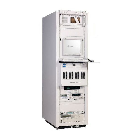
Spare rack space for application specific instruments Optional Electronic Load 66xxA Bottom 4 RU for Power Supply Power Supplies N6700B "Olympus" Front view Rear view Figure 3-1 TS-5020 Automotive Electronics Functional Tests System TS-5020 Automotive Electronics Functional Test System Site Preparation and Installation Guide... -
Page 28: System Dimensions
Table 3-1 Primary Rack Dimensions Size No. of Height Width Depth Estimated Bays per Weight Pallet 2.0m 2020mm 600mm 905mm 600 lbs (79.5 in.) (23.6 in.) (35.6 in.) TS-5020 Automotive Electronics Functional Test System Site Preparation and Installation Guide... -
Page 29: System Plan Drawing
ON/OFF switch at the rear of the E1135C PDU. BARRIER Instrument and service TS-5020 RACK access area (TOP VIEW) 600mm (23.6in) 1000mm 905mm (35.6in) (39in) Figure 3-2 Recommended TS-5020 Automotive Electronics Functional Layout (overhead view) TS-5020 Automotive Electronics Functional Test System Site Preparation and Installation Guide... -
Page 30: System Power Requirements
Unit (PDU) in your system. PDU E 1135C E 1135C M ulticom III /s E6 1 9 8B S L U Figure 3-3 Rear View of The TS-5020 Automotive Electronics Functional Test System TS-5020 Automotive Electronics Functional Test System Site Preparation and Installation Guide... -
Page 31: Minimum Power Requirements
• Use copper wire for the system drop between the AC source and system. • For Keysight E1135C PDU, a jumper wire may need to be installed for some options. This PDU has a mains disconnect switch that serves as master power for the entire rack. -
Page 32: Figure 3-4 E1135C Power Cord Installation
Product (provided with a protective earthing ground incorporated in the power cord). The mains plug shall be inserted into only a socket outlet provided with a protective earth contact. Figure 3-4 E1135C Power Cord Installation TS-5020 Automotive Electronics Functional Test System Site Preparation and Installation Guide... -
Page 33: Additional Power Information
These breaker must not be opened by force or permanent damage can result. Damaged caused by intentionally opening the breaker is not covered by warranty. TS-5020 Automotive Electronics Functional Test System Site Preparation and Installation Guide... -
Page 34: Mains Disconnect Requirements
“Disconnect Circuit Breaker Requirements” above plus the breaker must be rated a minimum 10,000 amperes interrupting capacity (AIC), for 100-240 V AC circuit, or 14,000 AIC for higher voltage circuit. 3-10 TS-5020 Automotive Electronics Functional Test System Site Preparation and Installation Guide... -
Page 35: Site Configuration For Ac Power
Use the same lengths of wire for the phase conductors, the neutral, and the ground. • It is extremely important that the neutral and ground be connected only at the transformer using an X-O bond. TS-5020 Automotive Electronics Functional Test System Site Preparation and Installation Guide 3-11... -
Page 36: Safety Ground Connection
Site Preparation and Power Requirements Safety Ground Connection As the Keysight TS-5020 is connected to the AC mains by means of a plug/socket connection, a permanent earth ground must be supplied to reduce the risk of electric shock. Make a permanent connection from the system rack to protective earth ground. -
Page 37: Ventilation
Automotive Electronics Functional Test System from mains before cleaning. Use a dry cloth or one slightly dampened with water to clean the external case parts. Do not attempt to clean internally. TS-5020 Automotive Electronics Functional Test System Site Preparation and Installation Guide 3-13... -
Page 38: System Transportation Instructions
Deploying the rack from its shipping carton requires moving it in WA R N I N G the Back- to-Front direction. NEVER stand directly in front of the rack when loading or unloading from a shipping carton. 3-14 TS-5020 Automotive Electronics Functional Test System Site Preparation and Installation Guide... -
Page 39: Installing The Keyboard, Mouse And Printer
Installing The Keyboard, Mouse and Printer Tools Required 4-2 Installation Procedure 4-3 Printer Tray 4-3 Mouse Tray 4-4 Palm Rest 4-5 Connect Keyboard and Mouse 4-6... -
Page 40: Tools Required
These nuts are located immediately below the flat panel display. If you need to locate the shelf elsewhere, four additional captive nuts are included with the shelf kit. TS-5020 Automotive Electronics Functional Test System Site Preparation and Installation Guide... -
Page 41: Installation Procedure
Attach the printer tray to the keyboard shelf. Make sure that the two hooks engage the shelf and the bottom of the tray is inserted into the tab under the keyboard shelf. Figure 4-1 Attaching Printer Tray TS-5020 Automotive Electronics Functional Test System Site Preparation and Installation Guide... -
Page 42: Mouse Tray
Attach the mouse tray to the keyboard shelf. Make sure that the two hooks engage the shelf and the bottom of the tray is inserted into the tab under the keyboard shelf. Figure 4-2 Attaching Mouse Tray TS-5020 Automotive Electronics Functional Test System Site Preparation and Installation Guide... -
Page 43: Palm Rest
Installing The Keyboard, Mouse and Printer Palm Rest Install the plastic palm rest by slipping it into the sots in the keyboard shelf. Figure 4-3 Installing Palm Rest TS-5020 Automotive Electronics Functional Test System Site Preparation and Installation Guide... -
Page 44: Connect Keyboard And Mouse
Power (ac mains) is provided at the PDU. You can route the ac power cable through the holes underneath the Test System Interface to the back of the system rack. TS-5020 Automotive Electronics Functional Test System Site Preparation and Installation Guide... - Page 45 This information is subject to change without notice. © Keysight Technologies 2006 - 2015 Edition 3, February 2015 *E2240-90000* E2240-90000 www.keysight.com...
Need help?
Do you have a question about the TS-5020 and is the answer not in the manual?
Questions and answers