
Related Manuals for Keysight TS-5400


Summary of Contents for Keysight TS-5400
- Page 1 Keysight TS-5400 High Performance PXI Functional Test System Site Preparation and Installation Guide...
- Page 2 FAR 27.401 or DFAR could result in personal injury or death. 227.7103-5 (c), as applicable in any Do not proceed beyond a WARNING technical data. notice until the indicated conditions are fully understood and met. Keysight TS-5400 Site Preparation and Installation Guide...
-
Page 3: Safety Summary
The protection provided by the TS-5400 system may be impaired if the system is used in a manner not specified by Keysight. -
Page 4: Before Applying Power
Fuses Use only fuses with the required rated current, voltage, and specified type (normal blow, time delay). Do not use repaired fuses or short-circuited fuse holders to avoid shock or fire hazard. Keysight TS-5400 Site Preparation and Installation Guide... -
Page 5: Operator Safety Information
Do not use the DMM for measurement on main circuits. The system is WARNING intended for measurements up to a maximum working voltage of 60 Vdc. Keysight TS-5400 Site Preparation and Installation Guide... -
Page 6: Safety Symbols
Keysight TS-5400 Site Preparation and Installation Guide... -
Page 7: Environmental Conditions
Environmental Conditions The TS-5400 Automotive Electronics Functional Test System is designed for indoor use only. Table 0-1 shows the general environmental requirements. Table 0-1 General environmental requirements Environment condition Requirement Maximum altitude 2000 m Operating temperature 5 °C to 40 °C... -
Page 8: Regulatory Markings
This text indicates that the product is The RCM mark is a registered an Industrial Scientific and Medical ISM 1-A trademark of the Australian Group 1 Class A product (CISPR 11, Communications and Media Authority. Clause 4). Keysight TS-5400 Site Preparation and Installation Guide... -
Page 9: Electrostatic Discharge (Esd) Precautions
Electrostatic Discharge (ESD) Precautions Static electricity is destructive to your production process and the TS-5400. Careless handling and poor site planning can cause system reliability problems and reduce your product yield. The system may not be as easily damaged as the modules you will be testing, but good anti-static planning will help ensure high reliability. -
Page 10: Waste Electrical And Electronic Equipment (Weee) Directive 2002/96/ Ec
To return this unwanted instrument, contact your nearest Keysight Service Center, or visit http://about.keysight.com/en/companyinfo/environment/takeback.shtml for more information. Sales and Technical Support To contact Keysight for sales and technical support, refer to the support links on the following Keysight website: – www.keysight.com/find/ts-5400 (product-specific information and support, software and documentation updates) –... -
Page 11: Table Of Contents
......29 Important recommendations about wiring ....30 Keysight TS-5400 Site Preparation and Installation Guide... - Page 12 ........39 Connect the keyboard and mouse ......39 Keysight TS-5400 Site Preparation and Installation Guide...
- Page 13 ... . .21 Figure 1-3 Rear view of the TS-5400 high performance PXI functional test system .......22...
- Page 14 THIS PAGE HAS BEEN INTENTIONALLY LEFT BLANK. Keysight TS-5400 Site Preparation and Installation Guide...
- Page 15 ..... . .19 Table 1-2 System electrical specifications ....23 Keysight TS-5400 Site Preparation and Installation Guide...
- Page 16 THIS PAGE HAS BEEN INTENTIONALLY LEFT BLANK. Keysight TS-5400 Site Preparation and Installation Guide...
- Page 17 Keysight TS-5400 High Performance PXI Functional Test System Site Preparation and Installation Guide Site Preparation and Power Requirements Preparing Your Site for the System System Power Requirements Mains Disconnect Requirements Safety Ground Connection System Transportation Instructions This chapter contains a detailed overview of the system software.
-
Page 18: Site Preparation And Power Requirements
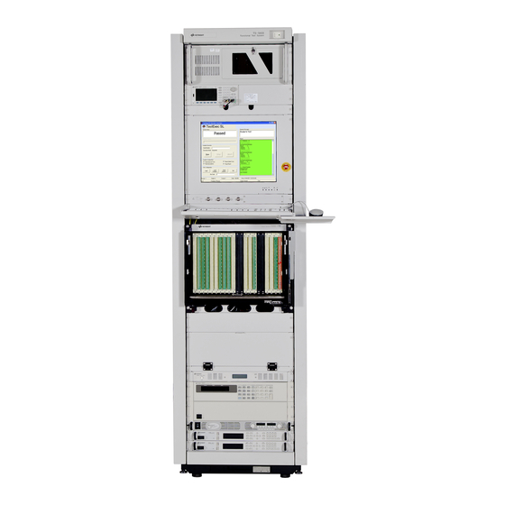
No operator-serviceable parts inside. Refer servicing to qualified personnel. WARNING To prevent electrical shock, do not remove instrument covers. The protection provided by the TS-5400 system may be impaired if the system is used in a manner not specified by Keysight. Typical system... -
Page 19: System Dimensions
TS-5400 high performance PXI functional test system System dimensions Table 1-1 shows dimensions for the primary rack only. Table 1-1 Primary rack dimensions Size 2.0 m No. of bays per pallet Height 2020 mm (79.5 in) Keysight TS-5400 Site Preparation and Installation Guide... -
Page 20: System Plan Drawing
The Remote ON/Standby switch at the upper right corner of the system rack WARNING turns off all equipment. The Main ON/OFF switch is located on the Keysight E1135C Power Distribution Unit (PDU), behind the rear cabinet door of the system (see Figure 1-3). - Page 21 Site Preparation and Power Requirements Barrier TS-5400 RACK 600mm (Top view) (23.6in) Instrument and service access area 905mm (35.6in) 1000mm Figure 1-2 Recommended TS-5400 high performance PXI functional test system layout (overhead view) Keysight TS-5400 Site Preparation and Installation Guide...
-
Page 22: System Power Requirements
Site Preparation and Power Requirements System Power Requirements The TS-5400 Functional Test System has been designed for use with a 3-phase AC voltage of either 240/415 V 3-Phase Wye with Neutral or a 120/208 V 3-Phase Wye with Neutral. Figure 1-3 shows the location of the Keysight Power Distribution Unit (PDU) in your system. -
Page 23: System Electrical Specifications
Site Preparation and Power Requirements The TS-5400 system must have the following requirements: – The AC mains power must be supplied to the E1135C PDU of the system. – The system is powered by a 240/415 V 3-Phase Wye with Neutral or a 120/208 V 3-Phase Wye with Neutral. -
Page 24: Configuring The Mains To The E1135C Pdu Connection
If loads of 220 V to 240 V are required, the neutral must be connected. NOTE The line-to-neutral voltage must not exceed 240 V. The voltage between CAUTION any two lines may be as high as 415 V. Keysight TS-5400 Site Preparation and Installation Guide... -
Page 25: Power Recommendations
Use a copper wire for the system drop between the AC source and the system. For the E1135C PDU, a jumper wire may need to be installed for some options. This PDU has a mains disconnect switch that serves as the master power for the entire rack. Keysight TS-5400 Site Preparation and Installation Guide... -
Page 26: Additional Power Information
Power is connected to the mains disconnect switch and a ground terminal attached to the chassis. For ease of installation, in areas where it meets local code requirements, use a multi-strand wire from the AC mains to the PDU. Keysight TS-5400 Site Preparation and Installation Guide... - Page 27 Reset the rocker by gently pushing it back in place. These breakers must not be opened by force or permanent damage can result. Damage caused by intentionally opening the breaker is not covered by warranty. Keysight TS-5400 Site Preparation and Installation Guide...
-
Page 28: Mains Disconnect Requirements
“Disconnect circuit breaker requirements” above and the breaker must be rated a minimum 10000 A interrupting capacity (AIC) for a 100 to 240 VAC circuit, or 14000 AIC for a higher voltage circuit. Keysight TS-5400 Site Preparation and Installation Guide... -
Page 29: Site Configuration For Ac Power
Tap into the main AC power source of the building consisting of 200 to 240 VAC, 47 to 63 Hz. Connect the power through a one-to-one or step-down transformer to the correct voltage for the system. Keysight TS-5400 Site Preparation and Installation Guide... -
Page 30: Important Recommendations About Wiring
– Use the same lengths of wire for the phase conductors, neutral, and ground. – It is extremely important that the neutral and ground be connected only at the transformer using an X-O bond. Keysight TS-5400 Site Preparation and Installation Guide... -
Page 31: Safety Ground Connection
Site Preparation and Power Requirements Safety Ground Connection As the TS-5400 is connected to the AC mains by means of a plug/socket connection, a permanent earth ground must be supplied to reduce the risk of electrical shock. Make a permanent connection from the system rack to the protective earth ground. -
Page 32: Ventilation
1 m (3.3 ft). Cleaning instructions To prevent electrical shock, disconnect the Keysight TS-5400 high WARNING performance PXI functional test system from the mains before cleaning. Use a dry cloth or one slightly dampened with water to clean the external case parts. -
Page 33: System Transportation Instructions
Avoid side-to-side or back-to-front movement except for final positioning. Deploying the rack from its shipping carton requires moving it in the WARNING back-to-front direction. NEVER stand directly in front of the rack when loading or unloading from a shipping carton. Keysight TS-5400 Site Preparation and Installation Guide... - Page 34 Site Preparation and Power Requirements THIS PAGE HAS BEEN INTENTIONALLY LEFT BLANK. Keysight TS-5400 Site Preparation and Installation Guide...
- Page 35 Keysight TS-5400 High Performance PXI Functional Test System Site Preparation and Installation Guide Keyboard, Mouse, and Printer Installation Tools Required Installation Procedure This chapter describes how to install the keyboard shelf, mouse tray, and printer tray onto the test rack; how to connect the keyboard and mouse; and how to...
-
Page 36: Keyboard, Mouse, And Printer Installation
Four captive nuts are installed on the front of the test rack to receive the NOTE keyboard shelf screws. These nuts are located immediately below the flat panel display. If you need to locate the shelf elsewhere, four additional captive nuts are included with the shelf kit. Keysight TS-5400 Site Preparation and Installation Guide... -
Page 37: Installation Procedure
Attach the printer tray to the keyboard shelf. Make sure that the two hooks engage the shelf and the bottom of the tray is inserted into the tab under the keyboard shelf. Printer tray Figure 2-1 Attaching the printer tray Keysight TS-5400 Site Preparation and Installation Guide... -
Page 38: Attach The Mouse Tray
Attach the mouse tray to the keyboard shelf. Make sure that the two hooks engage the shelf and the bottom of the tray is inserted into the tab under the keyboard shelf. Mouse tray Figure 2-2 Attaching the mouse tray Keysight TS-5400 Site Preparation and Installation Guide... -
Page 39: Install The Palm Rest
Connect the keyboard and mouse Connect the keyboard and mouse connectors to the extension cables (extension cables are labelled “Keyboard” and “Mouse”). Slide the excess cabling into the slot in the keyboard shelf. Keysight TS-5400 Site Preparation and Installation Guide... - Page 40 Figure 2-4 Connecting the keyboard and mouse If you have an optional strip printer (not provided by Keysight), connect its serial cable to one of the PC serial ports. Power (AC mains) is provided at the PDU. You can route the AC power cable through the holes underneath the Test System Interface to the back of the system rack.
- Page 41 This information is subject to change without notice. © Keysight Technologies 2012 - 2020 Edition 5, November 2020 Printed in Malaysia www.keysight.com...
Need help?
Do you have a question about the TS-5400 and is the answer not in the manual?
Questions and answers