Sign In
Upload
Manuals
Brands
Keysight Manuals
Test Equipment
TS-5020
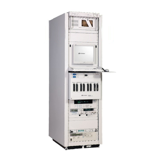
Keysight TS-5020 Manuals
Manuals and User Guides for Keysight TS-5020. We have
3
Keysight TS-5020 manuals available for free PDF download: Wiring Manual And Hardware Reference, Site Preparation And Installation Manual
Keysight TS-5020 Wiring Manual And Hardware Reference (125 pages)
Automotive Electronics Functional Test System
Brand:
Keysight
| Category:
Test Equipment
| Size: 12 MB
Table of Contents
Table of Contents
5
1 Legal Information
13
Warranty
14
Technology Licenses
14
Restricted Rights Legend
14
Service and Support
15
Keysight on the Web
15
Keysight by Phone
15
Legal Information
15
Table 1-1 Keysight Call Centers and Regional Headquarters
15
2 Safety and Regulatory Information
17
Safety Information
18
Safety Summary
18
Safety Notice
18
General
18
Environmental Conditions
19
Before Applying Power
19
Table 2-1 Environment Requirements
19
Ground the System
20
Fuses
20
Operator Safety Information
20
Safety Symbols and Regulatory Markings
21
Table 2-2 Safety Symbols and Regulatory Markings
21
Electrostatic Discharge (ESD) Precautions
23
Table 2-3 Suggested Anti-Static Solutions for Site Planning
23
End of Life: Waste Electrical and Electronic Equipment (WEEE) Directive 2002/96/EC
24
3 System Overview
25
System Intended Use
26
Instructions for Use
26
Test System Specifications and Capabilities
27
Table 3-1 Typical TS-5020 Instrumentation
27
Test Capabilities - Measurement Sample Methods
28
System Capability DC Accuracy Sample
28
Test System Interface Description
30
Test System Interface Connectors
30
Figure 3-1 Express Connect Test System Interface TC1 through TC4
31
Figure 3-2 Express Connect Test System Interface TC1 through TC8
32
Figure 3-3 Macpanel L2000 (TITAN) Test System Interface
34
Table 3-2 L2000 (TITAN) Slot 1 (System)
35
Table 3-3 L2000 (TITAN) Slot 2 (Instruments)
36
Table 3-4 L2000 (TITAN) Slot 3 (DAC)
37
Table 3-5 L2000 (TITAN) Slot 4 (RS232)
38
Table 3-6 L2000 (TITAN) Slot 6 (Pin Matrix 1St Card 34933A)
39
Table 3-7 L2000 (TITAN) Slot 7 to 9 (Matrix Card 34933A)
40
Table 3-8 L2000 (TITAN) Slot 6 (Pin Matrix 1St Card (34934A))
41
Table 3-9 L2000 (TITAN) Slot 7 (Pin Matrix 1St Card (34934A))
42
Table 3-10 L2000 (TITAN) Slot 8/21/23 (Pin Matrix Card (34934A))
43
Table 3-11 L2000 (TITAN) Slot 9/22/24 (Pin Matrix Card (34934A))
44
Table 3-12 L2000 (TITAN) Slot 12 to 15 (GP Relay Card (34938A))
45
Table 3-13 L2000 (TITAN) Slot 12 to 15 (GP Relay Card (34939A))
46
Table 3-14 L2000 (TITAN) Slot 11 to 20 (24-CH Load Card)
47
Table 3-15 L2000 (TITAN) Slot 13 to 20 (16-CH Load Card)
48
Table 3-16 L2000 (TITAN) Slot 13 to 20 (48-CH Load Card)
49
Table 3-17 L2000 (TITAN) Slot 13 to 20 (8-CH Load Card)
50
Table 3-18 L2000 (TITAN) Slot 16 & 18(Heavy Duty Load Card & Electronic Load)
51
Table 3-19 L2000 (TITAN) Slot 25 (RF)
51
Rack Layout with Express Connect Test System Interface
52
Figure 3-4 Typical TS-5020 System Rack with Express Connect Layout
52
Rack Layout with L2000 (TITAN) Test System Interface
53
Figure 3-5 Typical TS-5020 System with L2000 (TITAN) Test Interface
53
System Block Diagrams with Express Connect Test System Interface
54
Figure 3-6 TS-5020 Simplified System with Express Connect Block Diagram
54
System Block Diagrams with L2000 (TITAN) Test System Interface
55
Figure 3-7 TS-5020 Simplified System with L2000 (TITAN) Block Diagram
55
The Keysight 34980A Multifunction Switch/Measure Unit
56
Slot Allocation of the 34980A
56
Figure 3-8 Rear View of 34980A Multifunction Switch / Measure Unit
56
Figure 3-9. Cut-Out View of Slot 4 with Terminal Card to Create Instument/Pin
57
Figure 3-10 Multiple 34933A Configured as Instrumentation and Pin Matrix
58
Figure 3-11 Multiple 34934A Configured as Instrumentation and Pin Matrix
59
PC Cards
60
Keysight 53131 Universal Counter
60
Keysight 53220 Universal Counter
60
Keysight 33220 Function/Arbitrary Waveform Generator
61
Power Supplies
61
Keysight N6700 MPS
61
Channel Names
62
4 System Interconnects
63
System Interconnects for Express Connect Interface
64
Connector Keying
64
Figure 4-1 TC1-TC4 Connector Keying
64
Figure 4-2 TC1-TC8 Connector Key Configuration
64
Connectors and Tools
65
Connecting Wiring to Test Connectors TC1- TC8
65
Crimping Wires to Contacts
66
Figure 4-3 Crimping Wires to Contacts
66
Inserting Contacts and Assembling the Connectors
67
Figure 4-4 Assembling TC1 to TC4
67
Connecting to the Test System Interface
68
Figure 4-5 Connecting to the Test System Interface
68
ESD Protection Measures
69
Figure 4-6 Adding a Grounding Strap to Reduce ESD
69
Figure 4-7 Wrist Strap ESD Connector
70
Figure 4-8 Removing a Test Connector Contact
70
Operator Wrist Strap ESD Connector
70
Removing a Contact
70
Test Connector Signal Definitions
71
Figure 4-9 TC1 Pinouts
73
TC1-TC2 Pinouts
73
Figure 4-10 TC2 Pinouts
74
General TC Pins Assignment
75
Express Connect PCA Connector Definition and Pin Access
77
Figure 4-13. PCA Layout for Full Profile Express Connect (for TC1-TC8 Use)
77
Figure 4-14 View of Full Profile Express Connect PC Assembly
78
Figure 4-15. PCA Layout for Low Profile Express Connect (for TC1-TC4 Use)
79
Figure 4-18 TS-5020 Configuration Connector (J7 or J40)
82
High-Power Connector
83
Figure 4-20 Recommended System Grounding
84
System Grounding
84
System Interconnect for Mac Panel Interface
85
L2000 (TITAN) Connectors and Tools
85
5 Test System Interface Cables
91
U8970-61702 Dual Banana Metric Cable for GPIB/LXI DMM
93
U8970-61701 Cable BNC Coax to 3X1 (Non-Isolated)
93
U8970-61700 Cable Isolated Instrument BNC
93
Figure 5-1 U8970-61702 (Dual Banana Metric Cable)
93
Figure 5-2 U8970-61701 (Cable BNC Coax to 3X1)
93
Figure 5-3 U8970-61700 (Cable Isolated Instrument BNC)
93
Cables for Express Connect Interface
94
E6170-61623 Twinax DMM to Inst Matrix Cable
94
E6170-61626 DIO and Utility Power Supply to ICA Cable
94
Figure 5-4 E6170-61623 Twinax DMM to Inst Matrix Cable
94
Figure 5-5 E6170-61626 DIO and Utility Power Supply to ICA Cable
94
Table 5-1 E6170-61626 Cable Pinout Table
95
E6170-61627 DMM Trig 34980 to ICA
96
E6170-61628 DAC 34951 to ICA Cable
96
Figure 5-6 E6170-61627 DMM Trig 34980 to ICA
96
Figure 5-7 E6170-61628 DAC 34951 to ICA Cable
96
Table 5-2 E6170-61628 Cable Pinout Table
97
E6170-61629 GP Relay 34938A and Power Supply to ICA Cable
98
Figure 5-8 E6170-61629 Cable
98
Table 5-3 E6170-61629 Cable Pinout Table
99
E6170-61620 General Purpose 96-96 DINC Cable
100
E6170-61621 48 Channel Load Card Express Connect Cable
100
Figure 5-9 E6170-61620 General Purpose 96-96 DINC Cable
100
Figure 5-10 E6170-61621 48 Channel Load Card Express Connect Cable
100
E6170-61630 CAN PCI to ICA Cable
101
Figure 5-11 E6170-61630 CAN PCI to ICA Cable
101
E6170-61605 Cable for 8-CH/16-CH/24-CH Load Card to Express Connect
102
Figure 5-12 E6170-61605 Cable for Load Card to Express Connect. this Cable Can be Used for E6175A, N9377A, E6176A, E6177A, U7177A and N9378A
102
E6230-61603 Cable for 8-CH Heavy Duty Load Card to Express Connect
103
Figure 5-13 Cable for E6178B 8-CH Heavy Duty Load Card to Express Connect
103
Cables for L2000 (TITAN) Interface
104
E6218-61601 Cable, One Matrix (34933A) to L2000 (TITAN)
104
Figure 5-14 E6218-61601 Cable, One Matrix (34933A) to L2000 (TITAN)
104
E6218-61614 Cable, E6175A to L2000 (Titan)
105
E6218-61615 Cable, E6176A to L2000 (Titan)
105
Figure 5-15 E6218-61614 CABLE, E6175A to L2000 (TITAN)
105
E6218-61620 Cable, N9379A to L2000 (Titan)
106
Figure 5-17 E6218-61620 CABLE, N9379A to L2000 (TITAN)
106
E6218-61621 Cable, 34951-Dac to L2000 (Titan)
107
E6218-61622 Cable, 34980-DMM (Trig) to L2000 (Titan)
107
Figure 5-18 E6218-61621 CABLE, 34951-DAC to L2000 (TITAN)
107
Figure 5-19 E6218-61622 CABLE, 34980-DMM (TRIG) to L2000 (TITAN)
107
E6218-61624 Cable, E6178B to L2000 (Titan)
108
Figure 5-20 E6218-61624 CABLE, E6178B to L2000 (TITAN)
108
E6218-61625 Cable, One U7177A to L2000 (Titan)
109
Figure 5-21. E6218-61625 Cable, One U7177A to L2000. this Cable Is Used for E6177A
109
E6218-61627 Cable, Dio to L2000 (Titan)
110
E6218-61628 Cable, Ps to L2000 (Titan) (Med Current)
110
Figure 5-22 E6218-61627 CABLE, DIO to L2000 (TITAN)
110
Figure 5-23 E6218-61628 CABLE, PS to L2000 (TITAN) (MED CURRENT)
110
E6218-61629 Cable, 34938 to L2000 (Titan)
111
E6218-61630 Cable, Can to L2000 (Titan)
111
Figure 5-24 E6218-61629 CABLE, 34938 to L2000 (TITAN)
111
Figure 5-25 E6218-61630 CABLE, CAN to L2000 (TITAN)
111
E2240-61621 Cable, 34934A to ICA (TITAN)
112
Figure 5-26. E2240-61621 Cable, 34934A to ICA (TITAN). One Cable Requires Two TITAN
112
E2240-61622 Cable, 34939A to ICA (TITAN)
113
Figure 5-27 E2240-61622 Cable, 34934A to ICA (TITAN)
113
E2240-61623 Cable, Electronic Load to ICA (TITAN)
114
Figure 5-28. E2240-61623 Cable, Electronic Load to ICA (TITAN). this Cable Has an In-Line
114
E2240-61626 Cable, System Resources E6198B and PCI DIO 1750
115
E6218-61619 Cable, System Resources to L2000 (TITAN)
116
E6218-61626 CABLE, Dual 24-CH Load Card to L2000 (TITAN)
117
6 Replaceable and Spare Parts
119
Keysight E2230A Replaceable Parts
120
Keysight E2240A Recommended Spare Parts for Express Connect
122
Keysight E2240A Recommended Spare Parts for L2000 (TITAN)
123
Advertisement
Keysight TS-5020 Site Preparation And Installation Manual (55 pages)
Compact Functional Test System
Brand:
Keysight
| Category:
Test Equipment
| Size: 2 MB
Table of Contents
Table of Contents
5
Legal Information
12
Warranty
12
Technology Licenses
12
Restricted Rights Legend
12
Service and Support
13
Keysight on the Web
13
Keysight by Phone
13
Table 1-1 Keysight Call Centers and Regional Headquarters
13
2 Safety and Regulatory Information
15
Safety Information
16
Safety Summary
16
Safety Notice
16
General
16
Environmental Conditions
17
Before Applying Power
17
Ground the System
17
Table 2-1 Environment Requirements
17
Fuses
18
Operator Safety Information
18
Safety Symbols and Regulatory Markings
18
Table 2-2 Safety Symbols and Regulatory Markings
19
Declaration of Conformity
21
Electrostatic Discharge (ESD) Precautions
22
Table 2-3 Suggested Anti-Static Solutions for Site Planning
22
End of Life: Waste Electrical and Electronic Equipment (WEEE) Directive 2002/96/EC
23
3 Site Preparation and Power Requirements
25
Preparing Your Site for the System
26
Typical System
27
Figure 3-1 TS-5020 Automotive Electronics Functional Tests System
27
Figure 3-2 TS-5040 Rack Layout (Rear Mount)
28
Figure 3-3 TS-5040 Rack Layout (Top Mount)
29
System Dimensions
30
System Plan Drawing
30
Table 3-1 Test System Rack Dimensions
30
Figure 3-4 Recommended TS-5020 Automotive Electronics Functional Layout
31
Figure 3-5 Recommended TS-5040 Automotive Functional Test System Layout
31
System Power Requirements
32
Minimum Power Requirements
32
Figure 3-6 Rear View of the TS-5020 Automotive Electronics Functional Test
32
Power Recommendations
33
Table 3-2 AC Power Requirements
33
Figure 3-7 E3858B Mains Switch and Input
34
Additional Power Information
35
Figure 3-8 E1135C Power Cord Installation
35
Figure 3-9 Power Strip's Power Connector
36
Figure 3-10 Filtered Power Strip/Cord Location
36
Mains Disconnect Requirements
37
Disconnect Circuit Breaker Requirements
37
Mains Circuit Breaker Requirements
37
Site Configuration for AC Power
37
Important Recommendations about Wiring
38
Safety Ground Connection
39
Figure 3-11 Safety Ground Connections
39
Cleaning Instructions
40
Ventilation
40
System Transportation Instructions
41
Ramp Requirements
41
Hallway and Door Width Requirements
41
If the System Cannot be Moved in the Crate
41
4 Installing the Keyboard, Mouse, and Printer
43
Tools Required
44
Installation Procedure for TS-5020
45
Printer Tray
45
Figure 4-1 Attaching Printer Tray
45
Mouse Tray
46
Figure 4-2 Attaching Mouse Tray
46
Palm Rest
47
Figure 4-3 Installing Palm Rest
47
Connect Keyboard and Mouse
48
Figure 4-4 Connecting Keyboard and Mouse
48
Installation Procedure for TS-5040
49
Monitor Arm Pole
49
Figure 4-5 Attaching Monitor Arm
49
Monitor Arm
50
Figure 4-6 Installing Monitor Arm and Clamp
50
Keyboard Tray
51
Figure 4-7 Installing Keyboard Tray
51
Installation Procedure for TS-5040
52
PC and Peripheral Connections
52
Figure 4-8 PC and GPIB Connector Panel
52
Figure 4-9 Monitor Power Connector
52
Power Strip Breakers
53
Figure 4-10 Filtered Power Strip Circuit Breakers
53
Keysight TS-5020 Site Preparation And Installation Manual (45 pages)
Automotive Electronics Functional Test System
Brand:
Keysight
| Category:
Test Equipment
| Size: 1 MB
Table of Contents
Table of Contents
5
Legal Information
11
Warranty
11
Technology Licenses
11
Restricted Rights Legend
12
Service and Support
13
Keysight on the Web
13
Keysight by Phone
13
Legal Information
13
Table 1-1 Keysight Call Centers and Regional Headquarters
13
Safety and Regulatory Information
15
Safety Information
16
Safety Summary
16
Safety Notice
16
General
16
Environmental Conditions
17
Before Applying Power
17
Table 2-1 Environment Requirements
17
Ground the System
18
Fuses
18
Operator Safety Information
18
Safety Symbols and Regulatory Markings
19
Table 2-2 Safety Symbols and Regulatory Markings
19
Declaration of Conformity
21
Electrostatic Discharge (ESD) Precautions
22
Table 2-3 Suggested Anti-Static Solutions for Site Planning
22
End of Life: Waste Electrical and Electronic Equipment (WEEE) Directive 2002/96/EC
23
Site Preparation and Power Requirements
25
Preparing Your Site for the System
26
Typical System
27
Figure 3-1 TS-5020 Automotive Electronics Functional Tests System
27
System Dimensions
28
Table 3-1 Primary Rack Dimensions
28
System Plan Drawing
29
Figure 3-2. Recommended TS-5020 Automotive Electronics Functional Layout
29
System Power Requirements
30
Figure 3-3. Rear View of the TS-5020 Automotive Electronics Functional Test
30
Minimum Power Requirements
31
Power Recommendations
31
Table 3-2 AC Power Requirements
31
Figure 3-4 E1135C Power Cord Installation
32
Additional Power Information
33
Mains Disconnect Requirements
34
Disconnect Circuit Breaker Requirements
34
Mains Circuit Breaker Requirements
34
Site Configuration for AC Power
35
Important Recommendations about Wiring
35
Safety Ground Connection
36
Figure 3-5 Safety Ground Connections
36
Ventilation
37
Cleaning Instructions
37
System Transportation Instructions
38
Ramp Requirements
38
Hallway and Door Width Requirements
38
If the System Cannot be Moved in the Crate
38
Installing the Keyboard, Mouse and Printer
39
Tools Required
40
Installation Procedure
41
Printer Tray
41
Figure 4-1 Attaching Printer Tray
41
Mouse Tray
42
Figure 4-2 Attaching Mouse Tray
42
Palm Rest
43
Figure 4-3 Installing Palm Rest
43
Connect Keyboard and Mouse
44
Figure 4-4 Connecting Keyboard and Mouse
44
Advertisement
Advertisement
Related Products
Keysight TS-5400
Keysight TS-5040
Keysight Truevolt Series
Keysight 1000 Series
Keysight 1000A Series
Keysight 1000B Series
Keysight 100GE
Keysight 11636A
Keysight 11683A
Keysight 11683AZ-K01
Keysight Categories
Measuring Instruments
Test Equipment
Multimeter
Portable Generator
Power Supply
More Keysight Manuals
Login
Sign In
OR
Sign in with Facebook
Sign in with Google
Upload manual
Upload from disk
Upload from URL